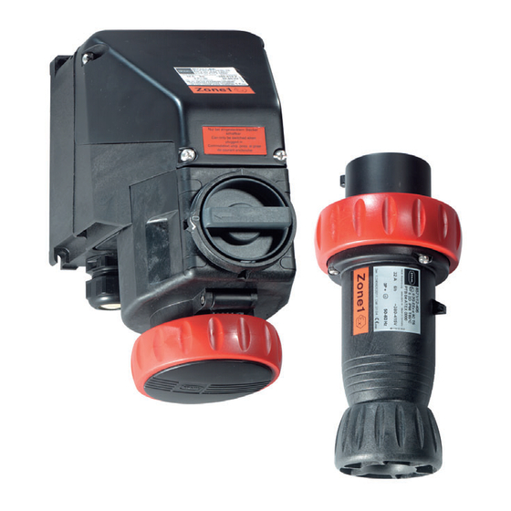
Stahl SolConex 8571/11 Operating Instructions Manual
Wall-mounted socket, plug
Hide thumbs
Also See for SolConex 8571/11:
- Manual (57 pages) ,
- Operating instructions manual (53 pages) ,
- Operating instructions manual (16 pages)

Related Manuals for Stahl SolConex 8571/11


Summary of Contents for Stahl SolConex 8571/11
- Page 1 Betriebsanleitung/Operating Instructions Wandsteckdose, Stecker Wall-Mounted Socket, Plug > 8571/11, 8571/12...
- Page 3 Betriebsanleitung Wandsteckdose, Stecker > 8571/11, 8571/12...
-
Page 4: Table Of Contents
Montage ........................8 Installation ......................9 Inbetriebnahme ....................12 Betrieb .........................12 Wartung .......................13 Zubehör und Ersatzteile ..................14 EG-Konformitätserklärung ...................15 Allgemeine Angaben 2.1 Hersteller R. STAHL Schaltgeräte GmbH Am Bahnhof 30 74638 Waldenburg Germany Tel.: +49 7942 943-0 Fax: +49 7942 943-4333 Internet: www.stahl-ex.com 2.2 Angaben zur Betriebsanleitung... -
Page 5: Allgemeine Sicherheitshinweise
Allgemeine Sicherheitshinweise Allgemeine Sicherheitshinweise 3.1 Sicherheitshinweise für Montage- und Bedienpersonal Die Betriebsanleitung enthält grundlegende Sicherheitshinweise, die bei Aufstellung, Betrieb und Wartung zu beachten sind. Nichtbeachtung hat eine Gefährdung für Personen, Anlage und Umwelt zur Folge. WARNUNG Gefahr durch unbefugte Arbeiten am Gerät! ... -
Page 6: Vorgesehener Einsatzbereich
Vorgesehener Einsatzbereich 3.3 Normenkonformität Die Wandsteckdose 8571/11 und der Stecker 8571/12 entsprechen folgenden Bestimmungen und Normen: Richtlinie 94/9/EG EN 50014, EN 50018, EN 50019, EN 50020, EN 50281-1-1 IEC 60079-0, IEC 60079-1, IEC 60079-7, IEC 60079-11, IEC 61241-1 IEC 60947-3, IEC 60947-4-1, IEC 60309, IEC 60529 Vorgesehener Einsatzbereich Die Wandsteckdose 8571/11 und der Stecker 8571/12 sind explosionsgeschützte ... -
Page 7: Technische Daten
Technische Daten Technische Daten Steckdose 8571/11 Explosionsschutz Gasexplosionsschutz E II 2 G Ex ed IIC T6 (Ta = -30 ... +40 °C) E II 2 G Ex ed IIC T5 (Ta = -30 ... +55 °C) mit eigensicheren Hilfskontakten: E II 2 G Ex ed [ia] IIC T6 (Ta = -30 ... +40 °C) E II 2 G Ex ed [ia] IIC T5 (Ta = -30 ... - Page 8 Technische Daten Kabel- und Leitungseinführungen Klemmbereich 13 mm ... 21 mm Kabeldurchmesser Kabelverschraubung 1 x M32 x 1,5 (auftragsbedingte Positionierung auch oben oder seitlich möglich) optional: oben max. 2 x M 32x 1,5; wahlweise auch Verschlussstopfen oder metallische Einführungen Verschlussstopfen 1 x M32 x 1,5 Gewicht 8571/11-4...
- Page 9 Technische Daten Anordnung der Schutzkontaktbuchse Position: Uhrzeit-Stellung, Ansicht: Vorderseite der Steckdose Beispiel: Uhrzeit-Stellung 06556E00 380 - 415 V = 6 h 02395E00 Anordnung der Kontaktbuchsen und Klemmenbezeichnungen 3 P + ¿ 3 P + N + ¿ 06555E00 06556E00 8571/11-4.. 8571/11-5..
-
Page 10: Transport, Lagerung Und Entsorgung
Transport, Lagerung und Entsorgung Transport, Lagerung und Entsorgung Transport Erschütterungsfrei in Originalkarton, nicht stürzen, vorsichtig handhaben. Lagerung Trocken in Originalverpackung lagern. Lagertemperatur: - 55 °C ... + 80 °C Entsorgung Umweltgerechte Entsorgung aller Bauteile gemäß den gesetzlichen Bestimmungen ... -
Page 11: Installation
Installation 7.2 Montage Stecker Typ 8571/12-... Zum Schutz gegen Verschmutzung der Steckerstifte kann eine passende Verschlusshaube verwendet werden (siehe Kapitel 12, „Zubehör und Ersatz- teile“). Gebrauchslage: Der Stecker sollte im ungesteckten Zustand mit den Kontakten nach un- ten hängend aufbewahrt werden. Installation WARNUNG Gefahr durch spannungsführende Teile! - Page 12 Installation 8.1 Installation Wandsteckdose Typ 8571/11-... Unter eine Anschlussklemme können zwei Leiter installiert werden. Leitermaterial und Leiterquerschnitt müssen dann gleich sein. Die Leiter können ohne besondere vorbereitende Maßnahmen angeschlossen werden. Abmessungen [mm] Hauptkontakte Hilfskontakte Hilfskontakte EEx i ...
- Page 13 Installation 8.2 Installation Stecker Typ 8571/12-... 11222E00 Verschraubung (1) abschrauben und Staubschutzplatte (2) entfernen. Druckring (3) und Dichtring (4) herausnehmen. Gehäuseschrauben (5) lösen und Steckergehäuse (6) abnehmen. ) durch Verschraubung, Druckring und Dichtung einführen. Leitung (max. 10 mm Innendurchmesser der Dichtung ggf.
-
Page 14: Inbetriebnahme
Die Wandsteckdose ist nur bei eingestecktem Stecker schaltbar. Bei gezogenem Stecker Klappdeckel mit dem Bajonettring verschließen. Es dürfen ausschließlich Stecker vom Typ 8571/12 und 8578/12 der Fa. R. STAHL verwendet werden. 10.2 Betrieb Stecker Typ 8571/12-... Nach einem Kurzschluss im Stromkreis Funktionsfähigkeit des Steckers kontrollieren. -
Page 15: Wartung
Wartung 11 Wartung WARNUNG Gefahr durch spannungsführende Teile! Schwerste Verletzungen drohen. Alle Anschlüsse und Verdrahtungen spannungsfrei schalten. Anschlüsse gegen unbefugtes Schalten sichern. WARNUNG Gefahr durch defekte Schaltkontakte! Verletzungen und Sachschäden drohen. Nach jedem Kurzschluss im Hauptstromkreis des Schalters den kompletten ... -
Page 16: Zubehör Und Ersatzteile
Zubehör und Ersatzteile 12 Zubehör und Ersatzteile Benennung Abbildung Beschreibung Art.Nr. Verschlussstopfen 8290/3-M32 143534 04840E00 Hilfskontakte 1 Schließer 150682 1 Öffner 150680 1 Schließer, Goldkontakt 150686 10341E00 1 Öffner, Goldkontakt 150684 Schutzkappen für Stecker 32 A 4-polig 150856 für Stecker 32 A 5-polig 150865 05365E00... -
Page 17: Eg-Konformitätserklärung
EG-Konformitätserklärung 13 EG-Konformitätserklärung 150942 / 8571601300 Wandsteckdose, Stecker 2013-06-21·BA00·III·de·07 8571/11, 8571/12... - Page 19 Operating Instructions Wall-Mounted Socket, Plug > 8571/11, 8571/12...
- Page 20 Installation ......................9 Commissioning ....................12 Operation ......................12 Maintenance ......................13 Accessories and Spare parts ................14 EC Declaration of Conformity ................15 General Information 2.1 Manufacturer R. STAHL Schaltgeräte GmbH Am Bahnhof 30 74638 Waldenburg Germany Phone: +49 7942 943-0 Fax: +49 7942 943-4333 Internet: www.stahl-ex.com...
-
Page 21: General Notes Regarding Safety
General Notes Regarding Safety General Notes Regarding Safety 3.1 Safety instructions for installation and operating personnel The operating instructions contain basic safety instructions which are to be observed during installation, operation and maintenance. Non-observance will endanger persons, plant and the environment. WARNING Risk due to unauthorised work being performed on the device! ... -
Page 22: Intended Area Of Application
Intended Area of Application 3.3 Conformity to Standards The wall-mounted socket 8571/11 and plug 8571/12 comply with the following directives and standards: Directive 94/9/EC EN 50014, EN 50018, EN 50019, EN 50020, EN 50281-1-1 IEC 60079-0, IEC 60079-1, IEC 60079-7, IEC 60079-11, IEC 61241-1 IEC 60947-3, IEC 60947-4-1, IEC 60309, IEC 60529 Intended Area of Application The wall-mounted socket 8571/11 and plug 8571/12 are explosion protected electrical... -
Page 23: Technical Data
Technical Data Technical Data Socket 8571/11 Explosion protection Gas explosion protection E II 2 G Ex d e IIC T6 (Ta = -30 ... +40 °C) E II 2 G Ex d e IIC T5 (Ta = -30 ... +55 °C) with intrinsically safe auxiliary contacts: E II 2 G Ex d e [ia] IIC T6 (Ta = -30 ... - Page 24 Technical Data Cable entries Clamp size 13 mm ... 21 mm outer diameter Cable gland 1 x M32 x 1.5 (positioning on the top or at the side, according to the order) optional: top max. 2 x M 32x 1.5; sealing plugs or metal entries are also available Stopping plug 1 x M32 x 1.5 Weight...
- Page 25 Technical Data Position of the protective earth (PE) contact Position: clock-hour position; View: front face of the socket Example: clock-hour position 06556E00 380 - 415 V = 6 o’clock 02395E00 Contact layout and terminal markings 3 P + ¿ 3 P + N + ¿ 06555E00 06556E00 8571/11-4..
-
Page 26: Transport, Storage And Disposal
Transport, Storage and Disposal Transport, Storage and Disposal Transport Shock-free in its original carton, do not drop, handle carefully. Storage Store in a dry place in its original packaging. Storage temperature range: - 55 °C ... + 80 °C Disposal Ensure environmentally friendly disposal of all components according to the legal ... -
Page 27: Installation
Installation 7.2 Assembly, wall-mounted socket, type 8571/12-... To prevent dirt from contaminating the contacts, a compatible sealing cap can be used (see Chapter 12, “Accessories and Spare Parts“). Position for use: When the plug is disconnected, it must be hung with the pins pointing downwards. - Page 28 Installation 8.1 Installation, wall-mounted socket, type 8571/11-... Two conductors can be clamped under a single terminal. Conductor material and cross sectional area must be identical.The conductors can be connected, without special preparatory measures. Dimensions [mm] Main contacts Auxiliary contacts Auxiliary contacts EEx i ...
- Page 29 Installation 8.2 Installation, plug, type 8571/12-... 11222E00 Screw the cable gland (1) off and remove the dust exclusion plate (2). Remove the pressure ring (3) and seal (4). Remove the shell securing screws (5) and remove the plug shell (6). ) through the cable gland (1), pressure ring (3) and ...
-
Page 30: Commissioning
When the plug is disconnected, lock the hinged cover with the bayo- net ring. Only type 8571/12 and 8578/12 plugs, manufactured by R. STAHL, must be used. 10.2 Operation, plug, type 8571/12-... If a short circuit occurs in the circuit, to which the plug is connected, check the function of the plug. -
Page 31: Maintenance
Maintenance 11 Maintenance WARNING Danger from live parts! Risk of serious injury. All connections and wiring must be disconnected from the power supply. Secure the connections against unauthorised re-connection. WARNING Danger through defective switch contacts! There is a risk of injury to persons and material damage. The complete flange socket must always be replaced, if a short circuit occurs ... -
Page 32: Accessories And Spare Parts
Accessories and Spare parts 12 Accessories and Spare parts Designation Figure Description Art. no. Sealing plugs 8290/3-M32 143534 04840E00 Auxiliary contacts 1 NO 150682 1 NC 150680 1 NO, gold contact 150686 10341E00 1 NC, gold contact 150684 Protection caps for plug 32 A 4 pole 150856... -
Page 33: Ec Declaration Of Conformity
EC Declaration of Conformity 13 EC Declaration of Conformity 150942 / 8571601300 Wall-Mounted Socket, Plug 2013-06-21·BA00·III·en·07 8571/11, 8571/12... - Page 36 150942 / 8571601300 2013-06-21·BA00·III·de/en·07...
Need help?
Do you have a question about the SolConex 8571/11 and is the answer not in the manual?
Questions and answers