Stahl SolConeX 8571/11 Series Operating Instructions Manual
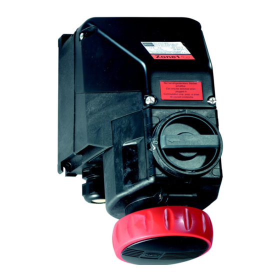
Wall-mounted socket
Hide thumbs
Also See for SolConeX 8571/11 Series:
- Manual (57 pages) ,
- Operating instructions manual (53 pages) ,
- Operating instructions manual (36 pages)

Subscribe to Our Youtube Channel
Related Manuals for Stahl SolConeX 8571/11 Series


Summary of Contents for Stahl SolConeX 8571/11 Series
- Page 1 Operating instructions Additional languages www.stahl-ex.com SolConeX Wall-Mounted Socket, 32 A Series 8571/11...
-
Page 2: Table Of Contents
Contents General Information ....................3 Manufacturer .......................3 Information Regarding the Operating Instructions ..........3 Further Documents .....................3 Conformity with Standards and Regulations ............3 Explanation of the Symbols ................3 Symbols in these Operating Instructions ............3 Warning Notes ....................4 Symbols on the Device or in the Circuit Diagrams ..........4 Safety Notes .......................5 Operating Instructions Storage ................5 Safe Use ......................5... -
Page 3: En En
Further Documents • Data sheet Plug and socket devices SolConeX & CES For further languages, see www.stahl-ex.com. Conformity with Standards and Regulations See certificates and EC Declaration of Conformity: www.stahl-ex.com. Explanation of the Symbols Symbols in these Operating Instructions Symbol... -
Page 4: 2.2 Warning Notes
Explanation of the Symbols Warning Notes Warning notes must be observed under all circumstances, in order to minimize the risk due to construction and operation. The warning notes have the following structure: • Signalling word: DANGER, WARNING, CAUTION, NOTICE • Type and source of danger/damage •... -
Page 5: Safety Notes
• Always consult with R. STAHL Schaltgeräte in case of operating conditions which deviate from the technical data. Modifications and Alterations... -
Page 6: 5 Technical Data
Technical Data Technical Data Explosion Protection Global (IECEx) Gas and dust IECEx PTB 05 0024 Ex de IIC T6 or T5 Ex tD A21 IP66 T60°C or T75°C Europe (ATEX) Gas and dust PTB 04 ATEX 1060 E II 2 G Ex d e IIC T6 (Ta = -30 ... +40 °C) E II 2 G Ex d e IIC T5 (Ta = -30 ... -
Page 7: 6 Transport And Storage
Stopping plug 1 x M32 x 1.5 For further technical data, see www.stahl-ex.com. Transport and Storage • Transport and store the device only in the original packaging. • Store the device in a dry place (no condensation) and vibration-free. -
Page 8: Mounting And Installation
Mounting and Installation Mounting and Installation Dimensions / Fastening Dimensions Dimensional drawings (all dimensions in mm [inch] – Subject to alterations 10339E00 8571/11-.. 32 A Arrangement of the earth contact sleeve Position: clock hour position, View: front side of the socket Example: Clock hour position 06556E00 380 ... - Page 9 Mounting and Installation Colour code and arrangement of socket contacts and terminal markings No. of poles* Frequency Voltage Colour code Position of the earth [Hz] contact sleeve 8571/11-4.. 50 and 60 200 ... 250 blue 3 P + ¿ 50 and 60 380 ...
-
Page 10: Mounting / Dismounting, Operating Position
Mounting and Installation Mounting / Dismounting, Operating Position 7.2.1 Assembly If mounted outdoors, equip the enclosure with protective roof or wall. Operating position Hinged cover facing downwards, connection chamber - upwards. • Fasten the wall-mounting socket by means of four screws in the vertical operating position on an even wall. -
Page 11: Installation
Mounting and Installation Installation WARNING Danger due to live components! Risk of severe injuries! • All connections and wiring must be disconnected from the power supply. • Secure the connections against unauthorized switching. DANGER Explosion hazard! Risk of injuries and material damage! •... - Page 12 Mounting and Installation Dimensions [mm] Main contacts Auxiliary contacts Ex i auxiliary contacts • Open the enclosure. • Lead the cable through the cable gland into the connection chamber. • Insert the conductors in the corresponding terminals and clamp them (for tightening torque, see chapter "Technical data").
-
Page 13: 8 Commissioning
The wall-mounting socket can be switched only with the inserted plug. If the plug has been disconnected, close the hinged cover with the bayonet ring. Only Type 8571/12 and 8578/12 plugs by R. STAHL may be used. 150942 / 8571601300 SolConeX Wall-Mounted Socket, 32 A 2014-01-21·BA00·III·en·08... -
Page 14: Maintenance And Repair
Maintenance and Repair Maintenance and Repair WARNING Unauthorized work being performed on the device! Risk of injuries and material damage! • Work performed on the device must only be carried out by appropriately authorized and trained personnel. 10.1 Maintenance • Consult the relevant national regulations to determine the type and extent of inspections. -
Page 15: 10.3 Repair
• Ensure environmentally friendly disposal of all components according to the statutory regulations. Accessories and Spare Parts NOTICE Use only original accessories and spare parts by R. STAHL Schaltgeräte GmbH. For accessories and spare parts, see data sheet on our homepage www.stahl-ex.com. 150942 / 8571601300 SolConeX Wall-Mounted Socket, 32 A 2014-01-21·BA00·III·en·08...
Need help?
Do you have a question about the SolConeX 8571/11 Series and is the answer not in the manual?
Questions and answers