Stahl SolConeX 8579/31 Series Operating Instructions Manual
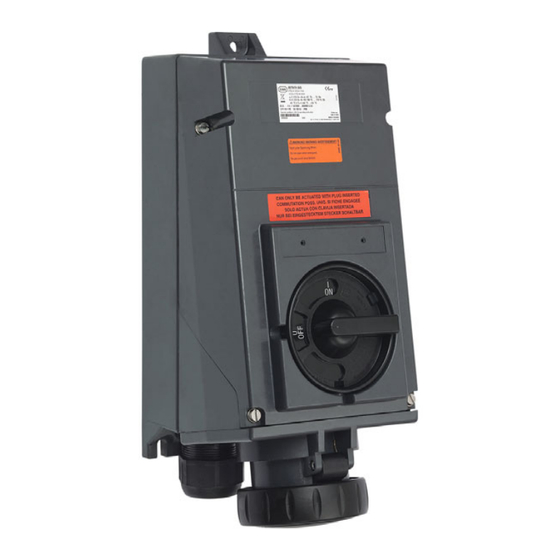
Wall-mounting socket, 63 a
Hide thumbs
Also See for SolConeX 8579/31 Series:
- Operating instructions manual (44 pages) ,
- Operating instructions manual (41 pages)

Subscribe to Our Youtube Channel
Related Manuals for Stahl SolConeX 8579/31 Series


Summary of Contents for Stahl SolConeX 8579/31 Series
- Page 1 Betriebsanleitung Additional languages r-stahl.com SolConeX Wandsteckdose, 63 A Reihe 8579/31...
-
Page 2: Table Of Contents
Inhaltsverzeichnis Allgemeine Angaben ...................3 Hersteller ......................3 Angaben zur Betriebsanleitung ................3 Weitere Dokumente ....................3 Konformität zu Normen und Bestimmungen ............3 Erläuterung der Symbole ..................4 Symbole in der Betriebsanleitung ...............4 Warnhinweise .....................4 Symbole am Gerät ....................5 Sicherheitshinweise ....................5 Aufbewahrung der Betriebsanleitung ..............5 Qualifikation des Personals ................5 Sichere Verwendung ...................6 Umbauten und Änderungen ................6... -
Page 3: De De
Die Originalbetriebsanleitung ist die englische Ausgabe. Diese ist rechtsverbindlich in allen juristischen Angelegenheiten. Weitere Dokumente • Datenblatt Steckvorrichtungen SolConeX Dokumente in weiteren Sprachen, siehe r-stahl.com. Konformität zu Normen und Bestimmungen Zertifikate und EU-Konformitätserklärung, siehe r-stahl.com. Das Gerät verfügt über eine IECEx-Zulassung. Zertifikat siehe IECEx-Homepage: http://iecex.iec.ch/... -
Page 4: Erläuterung Der Symbole
Erläuterung der Symbole Erläuterung der Symbole Symbole in der Betriebsanleitung Symbol Bedeutung Tipps und Empfehlungen zum Gebrauch des Geräts Gefahr allgemein Gefahr durch explosionsfähige Atmosphäre Warnhinweise Warnhinweise unbedingt befolgen, um das konstruktive und durch den Betrieb bedingte Risiko zu minimieren. Die Warnhinweise sind wie folgt aufgebaut: •... -
Page 5: Symbole Am Gerät
Normen und Bestimmungen umfasst. Für Tätigkeiten in explosionsgefährdeten Bereichen sind weitere Kenntnisse erforderlich! R. STAHL empfiehlt einen Kenntnisstand, der in folgenden Normen beschrieben wird: • IEC/EN 60079-14 (Projektierung, Auswahl und Errichtung elektrischer Anlagen) • IEC/EN 60079-17 (Prüfung und Instandhaltung elektrischer Anlagen) •... -
Page 6: 3.3 Sichere Verwendung
• Bei Betriebsbedingungen, die durch die technischen Daten des Geräts nicht abgedeckt werden, unbedingt bei der R. STAHL Schaltgeräte GmbH rückfragen. • Sicherstellen, dass das Gerät unbeschädigt ist. • Für Schäden, die durch fehlerhaften oder unzulässigen Einsatz des Geräts sowie durch Nichtbeachtung dieser Betriebsanleitung entstehen, besteht keine Haftung. -
Page 7: Funktion Und Geräteaufbau
Funktion und Geräteaufbau Funktion und Geräteaufbau GEFAHR Explosionsgefahr durch zweckentfremdete Verwendung! Nichtbeachten führt zu schweren oder tödlichen Verletzungen. • Gerät nur entsprechend den in dieser Betriebsanleitung festgelegten Betriebsbedingungen verwenden. • Gerät nur entsprechend dem in dieser Betriebsanleitung genannten Einsatzzweck verwenden. Funktion Einsatzbereich Die Wandsteckdose 8579/31 ist ein explosionsgeschütztes, elektrisches Betriebsmittel. -
Page 8: Technische Daten
Technische Daten Technische Daten Elektrische Daten Bemessungs- max. 690 V AC / max. 220 V DC betriebsspannung Frequenz 50 / 60 Hz (bei Frequenzen ) 100 Hz Reduzierung auf 50 A erforderlich) Spannungstoleranz -10 ... +10 % Bemessungs- 63 A betriebsstrom Bemessungs- bis 750 V... - Page 9 Technische Daten Technische Daten Mechanische Daten Anzahl der Pole 4-polig (3P + ¿) / 5-polig (3P + N + ¿) (N-Leiter geschaltet) Hilfskontakte Standard- 8080/1-1: 1 Öffner + 1 Schließer im linken Einbauschacht ausführung Schließer EIN nacheilend Schließer AUS voreilend (> 20 ms vor den Hauptkontakten) Öffner gleichschaltend Mögliche max.
- Page 10 Technische Daten Technische Daten Gewicht 8579/31-4 7,8 kg 8579/31-5 8,2 kg Lebensdauer > 20.000 Schaltzyklen (elektrisch und mechanisch) Anzugsdrehmoment Klemmen: Hauptkontakt: 6 Nm Hilfskontakt: 0,4 Nm Deckelschrauben: 3,5 Nm Leitungs- einführungen Kabel- 1 x M50 x 1,5 verschraubung (auftragsbedingte Positionierung auch oben oder seitlich möglich) Gewinde- Klemmbereich Klemm- Anzugs-...
- Page 11 Technische Daten Anordnung der Schutzkontaktbuchse Position: Uhrzeit-Stellung, Ansicht: Vorderseite der Steckdose 02395E00 Anordnung der Kontaktbuchsen und Klemmenbezeichnungen 4-polig (3P + ¿) 5-polig (3P + N + ¿) 06556E00 06555E00 8579/31-4.. 8579/31-5.. Anordnung der Kontaktbuchsen und Klemmenbezeichnungen in der 6h-Stellung (Ansicht von der Vorderseite der Steckdose auf die Kontaktbuchsen) 201300 / 8579610300 SolConeX Wandsteckdose, 63 A 2020-11-03·BA00·III·de·05...
- Page 12 Spannungen und Frequenzen gemäß IEC 60309-2 Hauptsächlich für Schiffsinstallationen Frequenzen ) 100 Hz führen zu stärkerer Erwärmung. Dies muss durch Stromreduzierung auf 50 A kompensiert werden. Weitere technische Daten, siehe r-stahl.com. SolConeX Wandsteckdose, 63 A 201300 / 8579610300 Reihe 8579/31...
-
Page 13: Transport Und Lagerung
Transport und Lagerung Transport und Lagerung • Gerät nur in Originalverpackung transportieren und lagern. • Gerät trocken (keine Betauung) und erschütterungsfrei lagern. • Gerät nicht stürzen. Montage und Installation Maßangaben / Befestigungsmaße Maßzeichnungen (alle Maße in mm [Zoll]) – Änderungen vorbehalten 13 [0,51] 9 [0,35] 152 [5,98]... -
Page 14: 7.2 Montage / Demontage, Gebrauchslage
Montage und Installation Montage / Demontage, Gebrauchslage 7.2.1 Montage Das Gerät ist für den Einsatz im Innen- und Außenbereich geeignet. • Bei Einsatz im Außenbereich Gehäuse und explosionsgeschütztes, elektrisches Betriebsmittel mit Schutzdach oder -wand ausrüsten. Gebrauchslage • Klappdeckel vorzugsweise nach unten, Anschlussraum nach oben. - Page 15 • Beigefügtes Schaltbild mit entsprechender Schaltfunktion auf Typschild des Schalters kleben. 12435E00 Demontage Hilfskontakte • Hilfskontakt-Schlüssel (Art.-Nr. 201909) mit dem Stahl-Logo nach oben (!) zwischen Hilfskontakt und Schalterdeckel einführen. • Hilfskontakt zusammen mit Hilfskontakt-Schlüssel herausziehen. 12436E00 201300 / 8579610300 SolConeX Wandsteckdose, 63 A 2020-11-03·BA00·III·de·05...
- Page 16 Montage und Installation Hilfskontakte in Ex i Stromkreisen Werden die Hilfskontakte des Typs 8080/1 in Ex i Stromkreisen eingesetzt, müssen diese mit einer Abdeckung (Art.-Nr. 169683) versehen werden. Die kundenseitige Installation eines eigensicheren Hilfskontakts ist nur dann zulässig, wenn an den beiden Klemmen links und rechts des verwendeten Einbauschachts keine Abgriffklemmen installiert sind! Montage Ex i Abdeckung für Hilfskontakte Die Ex i Abdeckung dient zur Sicherstellung des erforderlichen Fadenmaßes...
- Page 17 Montage und Installation Installation GEFAHR Explosionsgefahr durch unzureichende Schutzmaßnahmen! Nichtbeachten führt zu schweren oder tödlichen Verletzungen. • Durch geeignete Leiterauswahl sicherstellen, dass maximal zulässige Leitertemperaturen nicht überschritten werden. • Leitungen eigensicherer Stromkreise getrennt von den Leitungen nicht-eigensicherer Stromkreise verlegen. Die dafür erforderlichen Abstandswerte dem Abschnitt "Trennung eigensichere Stromkreise gegen nicht-eigensichere Stromkreise"...
- Page 18 Montage und Installation Unter eine Anschlussklemme können zwei Leiter installiert werden. Leitermaterial und Leiterquerschnitt müssen dann gleich sein. Die Leiter können ohne besondere vorbereitende Maßnahmen angeschlossen werden. Trennung "eigensichere Stromkreise" gegen "nicht-eigensichere Stromkreise" • 6 mm für einen Scheitelwert der Nennspannung ( 375 V •...
- Page 19 Montage und Installation • Gehäuse öffnen. • Leitungen durch Leitungseinführung in Anschlussraum führen. • Leitungen abisolieren. • Leitungen in entsprechende Klemmen einführen und festklemmen (Anzugsdrehmoment siehe Kapitel "Technische Daten"). 11201E00 Dabei abisolierte Leitungsenden A [mm] B [mm] vollständig unter die Klemme stecken.
-
Page 20: Inbetriebnahme
Die Wandsteckdose darf nur in komplett montiertem Zustand betrieben werden. Die Wandsteckdose ist nur bei eingestecktem Stecker schaltbar. Bei gezogenem Stecker Klappdeckel mit dem Bajonettring verschließen. Es dürfen ausschließlich Stecker vom Typ 8579/12 der Fa. R. STAHL verwendet werden. SolConeX Wandsteckdose, 63 A 201300 / 8579610300 Reihe 8579/31... -
Page 21: Abschließen Mit Vorhängeschloss
Instandhaltung, Wartung, Reparatur Abschließen mit Vorhängeschloss Der Drehgriff zum Schalten der Steckdose kann mit einem Vorhängeschloss (max. Bügeldurchmesser 8 mm) in 0- oder I-Stellung abgeschlossen werden. Instandhaltung, Wartung, Reparatur 10.1 Instandhaltung • Art und Umfang der Prüfungen den entsprechenden nationalen Vorschriften entnehmen. -
Page 22: 10.3 Reparatur
Norm IEC 60079-1:2014 sind nicht zulässig. 10.4 Rücksendung • Rücksendung bzw. Verpackung der Geräte nur in Absprache mit R. STAHL durchführen! Dazu mit der zuständigen Vertretung von R. STAHL Kontakt aufnehmen. Für die Rücksendung im Reparatur- bzw. Servicefall steht der Kundenservice von R. -
Page 23: Entsorgung
Fehlfunktion oder Geräteschaden durch den Einsatz nicht originaler Bauteile. Nichtbeachten kann Sachschaden verursachen! • Nur Original-Zubehör und Original-Ersatzteile der R. STAHL Schaltgeräte GmbH verwenden. Zubehör und Ersatzteile, siehe Datenblatt auf Homepage r-stahl.com. 201300 / 8579610300 SolConeX Wandsteckdose, 63 A 2020-11-03·BA00·III·de·05... - Page 25 Operating instructions Additional languages r-stahl.com SolConeX Wall-mounting socket, 63 A Series 8579/31...
- Page 26 Contents General Information ....................3 Manufacturer .......................3 Information regarding the Operating Instructions ..........3 Further Documents .....................3 Conformity with Standards and Regulations ............3 Explanation of the Symbols ................4 Symbols in these Operating Instructions ............4 Warning Notes ....................4 Symbols on the Device ..................5 Safety Notes .......................5 Operating Instructions Storage ................5 Personnel Qualification ..................5...
-
Page 27: En En
• SolConeX plug and socket devices data sheet For documents in additional languages, see r-stahl.com. Conformity with Standards and Regulations See certificates and EU Declaration of Conformity: r-stahl.com. The device has IECEx approval. For certificate please refer to the IECEx homepage: http://iecex.iec.ch/ Further national certificates can be downloaded via the following link: https://r-stahl.com/en/global/support/downloads/. -
Page 28: Explanation Of The Symbols
Explanation of the Symbols Explanation of the Symbols Symbols in these Operating Instructions Symbol Meaning Tips and recommendations on the use of the device General danger Danger due to explosive atmosphere Warning Notes Warnings must be observed under all circumstances, in order to minimize the risk due to construction and operation. -
Page 29: Symbols On The Device
Specialists who perform these tasks must have a level of knowledge that meets applicable national standards and regulations. Additional knowledge is required for tasks in hazardous areas! R. STAHL recommends having a level of knowledge equal to that described in the following standards: •... -
Page 30: 3.3 Safe Use
• Use the device in accordance with its intended and approved purpose only. • Always consult with R. STAHL Schaltgeräte GmbH if using the device under operating conditions which are not covered by the technical data. • Make sure that the device is not damaged. -
Page 31: Function And Device Design
Function and Device Design Function and Device Design DANGER Explosion hazard due to improper use! Non-compliance results in severe or fatal injuries. • Use the device only in accordance with the operating conditions described in these operating instructions. • Use the device only for the intended purpose specified in these operating instructions. -
Page 32: Technical Data
Technical Data Technical Data Electrical data Rated operational Max. 690 V AC/max. 220 V DC voltage Frequency 50/60 Hz (for frequencies ) 100 Hz reduction to 50 A required) Voltage tolerance -10 to +10 % Rated operational 63 A current Rated insulation up to 750 V voltage... - Page 33 Technical Data Technical Data Mechanical data Number of poles 4-pole (3P + ¿)/5-pole (3P + N + ¿) (N-conductor connected) Auxiliary contacts Standard version 8080/1-1: 1 NC + 1 NO in the left installation slot NO contact ON delayed NO contact OFF leading (> 20 ms before opening of the main contacts) NC contacts synchronizing Possible auxiliary max.
- Page 34 Technical Data Technical Data Weight 8579/31-4 7.8 kg 8579/31-5 8.2 kg Service life > 20,000 switching cycles (electric and mechanical) Tightening torque Terminals: Main contact: 6 Nm Auxiliary contact: 0.4 Nm Cover screws: 3.5 Nm Cable glands Cable gland 1 x M50 x 1.5 (positioning on the top or at the side, according to the order) Thread Clamping...
- Page 35 Technical Data Arrangement of the earth contact sleeve Position: Time position, view: Front side of the socket 02395E00 Arrangement of socket contacts and terminal markings 4-pole (3P + ¿) 5-pole (3P + N + ¿) 06556E00 06555E00 8579/31-4.. 8579/31-5.. Arrangement of the socket contacts and terminal markings in the 6h position (view from the front side of the socket to the socket contacts) 201300 / 8579610300 SolConeX Wall-mounting socket, 63 A...
- Page 36 IEC 60309-2 Mainly for ship installations Frequencies ) 100 Hz lead to increased heating. This must be offset by reducing the current to 50 A. For further technical data, see r-stahl.com. SolConeX Wall-mounting socket, 63 A 201300 / 8579610300 Series 8579/31 2020-11-03·BA00·III·en·05...
-
Page 37: Transport And Storage
Transport and Storage Transport and Storage • Transport and store the device only in the original packaging. • Store the device in a dry place (no condensation) and vibration-free. • Do not drop the device. Mounting and Installation Dimensions / Fastening Dimensions Dimensional drawings (all dimensions in mm [inches]) –... -
Page 38: 7.2 Mounting / Dismounting, Operating Position
Mounting and Installation Mounting / Dismounting, Operating Position 7.2.1 Assembly This device is suitable for outdoor and indoor use. • Provide a protective roof or wall if the enclosure and explosion-protected electrical equipment are used outdoors. Operating position • Hinged cover preferably facing downwards, connection chamber facing upwards. - Page 39 Dismounting the auxiliary contacts • Insert the auxiliary contact key (Art. no. 201909) between the auxiliary contact and the switch cover with the Stahl logo pointing upwards (!). • Pull out the auxiliary contact along with the auxiliary contact key.
- Page 40 Mounting and Installation Auxiliary contacts in Ex i circuits If the auxiliary contacts of Type 8080/1 are used in Ex i circuits, they must be provided with a covering (Art. No. 169683). The customer is only allowed to install an intrinsically safe auxiliary contact if no pick-off terminal blocks are mounted on the two terminals located on the left and right side of the installation slot used! Mounting Ex i covering for auxiliary contacts...
-
Page 41: Installation
Mounting and Installation Installation DANGER Explosion hazard due to insufficient protective measures! Non-compliance results in severe or fatal injuries. • Select suitable cables to ensure that the maximum permissible conductor temperatures are not exceeded. • Lay cables in intrinsically safe circuit separately to cables in non-intrinsically-safe circuits. - Page 42 Mounting and Installation Two conductors can be installed under one connection terminal. Material and cross section of both conductors must be identical. The conductors can be connected without any special preparations. Separating "intrinsically safe circuits" from "non-intrinsically-safe circuits" • 6 mm for a peak nominal voltage ( 375 V •...
- Page 43 Mounting and Installation • Open the enclosure. • Guide the conductors through the cable entry and into the connection chamber. • Strip the conductors. • Insert the conductors into the corresponding terminals and clamp them (for tightening torque, see chapter "Technical data"). 11201E00 Insert the stripped cable ends A [mm]...
-
Page 44: Commissioning
The wall-mounting socket can be switched only with the plug inserted. If the plug has been disconnected, lock the hinged cover with the bayonet ring. Only Type 8579/12 plugs from R. STAHL may be used. SolConeX Wall-mounting socket, 63 A 201300 / 8579610300 Series 8579/31 2020-11-03·BA00·III·en·05... -
Page 45: Padlocking With A Padlock
Maintenance, Overhaul, Repair Padlocking with a Padlock The rotary actuator for switching the socket can be locked with a padlock (max. bracket diameter of 8 mm) in 0 or I positions. Maintenance, Overhaul, Repair 10.1 Maintenance • Consult the relevant national regulations to determine the type and extent of inspections. -
Page 46: 10.3 Repair
• Only return or package the devices after consulting R. STAHL! Contact the responsible representative from R. STAHL. R. STAHL's customer service is available to handle returns if repair or service is required. • Contact customer service personally. • Go to the r-stahl.com website. -
Page 47: Disposal
Malfunction or damage to the device due to the use of non-original components. Non-compliance can result in material damage. • Use only original accessories and spare parts from R. STAHL Schaltgeräte GmbH. For accessories and spare parts, see data sheet on our homepage r-stahl.com.
Need help?
Do you have a question about the SolConeX 8579/31 Series and is the answer not in the manual?
Questions and answers