Stahl SolConeX 8571/11 Series Operating Instructions Manual
Wall-mounted socket, 32 a
Hide thumbs
Also See for SolConeX 8571/11 Series:
- Manual (57 pages) ,
- Operating instructions manual (36 pages) ,
- Operating instructions manual (16 pages)

Related Manuals for Stahl SolConeX 8571/11 Series


Summary of Contents for Stahl SolConeX 8571/11 Series
- Page 1 Betriebsanleitung Additional languages r-stahl.com SolConeX Wandsteckdose, 32 A Reihe 8571/11...
-
Page 2: Table Of Contents
Inhaltsverzeichnis Allgemeine Angaben ...................3 Hersteller ......................3 Angaben zur Betriebsanleitung ................3 Weitere Dokumente ....................3 Konformität zu Normen und Bestimmungen ............3 Erläuterung der Symbole ..................4 Symbole in der Betriebsanleitung ...............4 Warnhinweise .....................4 Symbole am Gerät ....................5 Sicherheitshinweise ....................5 Aufbewahrung der Betriebsanleitung ..............5 Qualifikation des Personals ................5 Sichere Verwendung ...................6 Umbauten und Änderungen ................6... -
Page 3: De De
Die Originalbetriebsanleitung ist die englische Ausgabe. Diese ist rechtsverbindlich in allen juristischen Angelegenheiten. Weitere Dokumente • Datenblatt Steckvorrichtungen SolConeX Dokumente in weiteren Sprachen, siehe r-stahl.com. Konformität zu Normen und Bestimmungen Zertifikate und EU-Konformitätserklärung, siehe r-stahl.com. Das Gerät verfügt über eine IECEx-Zulassung. Zertifikat siehe IECEx-Homepage: http://iecex.iec.ch/... -
Page 4: Erläuterung Der Symbole
Erläuterung der Symbole Erläuterung der Symbole Symbole in der Betriebsanleitung Symbol Bedeutung Tipps und Empfehlungen zum Gebrauch des Geräts Gefahr allgemein Gefahr durch explosionsfähige Atmosphäre Warnhinweise Warnhinweise unbedingt befolgen, um das konstruktive und durch den Betrieb bedingte Risiko zu minimieren. Die Warnhinweise sind wie folgt aufgebaut: •... -
Page 5: Symbole Am Gerät
Normen und Bestimmungen umfasst. Für Tätigkeiten in explosionsgefährdeten Bereichen sind weitere Kenntnisse erforderlich! R. STAHL empfiehlt einen Kenntnisstand, der in folgenden Normen beschrieben wird: • IEC/EN 60079-14 (Projektierung, Auswahl und Errichtung elektrischer Anlagen) • IEC/EN 60079-17 (Prüfung und Instandhaltung elektrischer Anlagen) •... -
Page 6: 3.3 Sichere Verwendung
• Bei Betriebsbedingungen, die durch die technischen Daten des Geräts nicht abgedeckt werden, unbedingt bei der R. STAHL Schaltgeräte GmbH rückfragen. • Sicherstellen, dass das Gerät unbeschädigt ist. • Für Schäden, die durch fehlerhaften oder unzulässigen Einsatz des Geräts sowie durch Nichtbeachtung dieser Betriebsanleitung entstehen, besteht keine Haftung. -
Page 7: Funktion Und Geräteaufbau
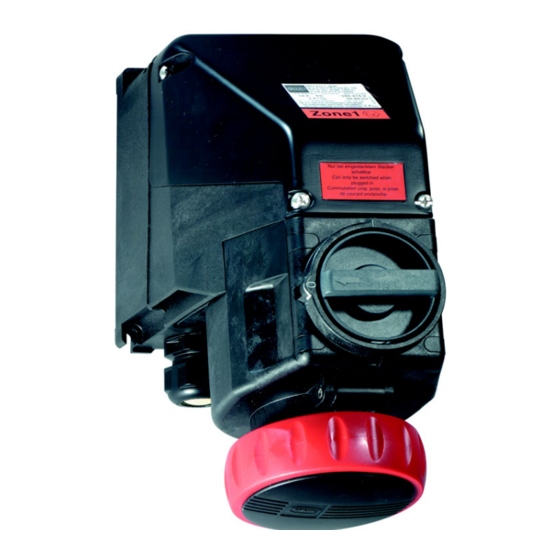
Funktion und Geräteaufbau Funktion und Geräteaufbau GEFAHR Explosionsgefahr durch zweckentfremdete Verwendung! Nichtbeachten führt zu schweren oder tödlichen Verletzungen. • Gerät nur entsprechend den in dieser Betriebsanleitung festgelegten Betriebsbedingungen verwenden. • Gerät nur entsprechend dem in dieser Betriebsanleitung genannten Einsatzzweck verwenden. Funktion Einsatzbereich Die Wandsteckdose 8571/11 ist ein explosionsgeschütztes, elektrisches Betriebsmittel. -
Page 8: Technische Daten
Technische Daten Technische Daten Elektrische Daten Bemessungs- betriebsspannung Hauptkontakte 8571/11-4..: max. 690 V AC / max. 110 V DC 8571/11-5..: max. 690 V AC / max. 110 V DC Hilfskontakte max. 500 V AC / max. 110 V DC Frequenz 50 / 60 Hz (bei Frequenzen ) 100 Hz Reduzierung auf 25 A erforderlich) Spannungstoleranz -10 ... - Page 9 Technische Daten Technische Daten Umgebungsbedingungen Betriebstemperatur- -50 ... +65 °C bereich -40 ... +65 °C, optional (silikonfrei) (Die Lagertemperatur entspricht der Umgebungstemperatur) Bei Frequenzen < 100 Hz 4-polig (3P + ¿) - mit Hilfskontakten Temperatur- klasse Umgebungs- Ta ( Ta ( Ta ( Ta ( Ta (...
- Page 10 Technische Daten Technische Daten 4-polig (3P + ¿) - ohne Hilfskontakte Temperatur- klasse Umgebungs- Ta ( Ta ( Ta ( Ta ( Ta ( Ta ( Ta ( Ta ( Ta ( temperatur °C °C °C °C °C °C °C °C °C Anschluss-...
- Page 11 Technische Daten Technische Daten 5-polig (3P + N + ¿) - mit Hilfskontakten Temperatur- klasse Umgebungs- Ta ( Ta ( Ta ( Ta ( Ta ( Ta ( Ta ( Ta ( Ta ( temperatur °C °C °C °C °C °C °C °C...
- Page 12 Technische Daten Technische Daten 5-polig (3P + N + ¿) - ohne Hilfskontakte Temperatur- klasse Umgebungs- Ta ( Ta ( Ta ( Ta ( Ta ( Ta ( Ta ( Ta ( Ta ( temperatur °C °C °C °C °C °C °C °C...
- Page 13 Technische Daten Technische Daten Mechanische Daten Anzahl der Pole 4-polig (3P + ¿) / 5-polig (3P + N + ¿) (N-Leiter geschaltet) Hilfskontakte Optional max. 2 Hilfskontakte (EIN - nacheilend, AUS - voreilend) Hilfskontakte in Ex i-Ausführung sind mit Goldkontakten ausgeführt. Optional in NAMUR-Widerstandsbeschaltung.
- Page 14 Technische Daten Technische Daten Leitungs- einführungen Kabel- 1 x M32 x 1,5 verschraubung (auftragsbedingte Positionierung auch oben oder seitlich möglich) optional: oben max. 2 x M32 x 1,5; wahlweise auch Verschlussstopfen oder metallische Einführungen Gewinde- Klemmbereich Klemm- Anzugs- Anzugs- größe bereich dreh- dreh-...
- Page 15 Technische Daten Anordnung der Schutzkontaktbuchse Position: Uhrzeit-Stellung, Ansicht: Vorderseite der Steckdose Beispiel: Uhrzeit-Stellung 06556E00 380 ... 415 V = 6 h 02395E00 Anordnung der Kontaktbuchsen und Klemmenbezeichnungen 4-polig (3P + ¿) 5-polig (3P + N + ¿) 19265E00 19266E00 8571/11-4.. 8571/11-5..
- Page 16 Spannungen und Frequenzen gemäß IEC 60309-2 Hauptsächlich für Schiffsinstallationen Frequenzen ) 100 Hz führen zu stärkerer Erwärmung. Dies muss durch Stromreduzierung auf 25 A kompensiert werden. Weitere technische Daten, siehe r-stahl.com. SolConeX Wandsteckdose, 32 A 276198 / 8571640300 Reihe 8571/11...
-
Page 17: Transport Und Lagerung
Transport und Lagerung Transport und Lagerung • Gerät nur in Originalverpackung transportieren und lagern. • Gerät trocken (keine Betauung) und erschütterungsfrei lagern. • Gerät nicht stürzen. Montage und Installation Maßangaben / Befestigungsmaße Maßzeichnungen (alle Maße in mm [Zoll]) – Änderungen vorbehalten 55,50 [2,19] 122,50 [4,82]... -
Page 18: 7.2 Montage / Demontage, Gebrauchslage
Montage und Installation Montage / Demontage, Gebrauchslage 7.2.1 Montage Das Gerät ist für den Einsatz im Innen- und Außenbereich geeignet. • Bei Einsatz im Außenbereich Gehäuse und explosionsgeschütztes, elektrisches Betriebsmittel mit Schutzdach oder -wand ausrüsten. Gebrauchslage • Klappdeckel vorzugsweise nach unten, Anschlussraum nach oben. - Page 19 Montage und Installation Montage Hilfskontakte • Gehäuse öffnen. • Hilfskontakte wahlweise in die linke oder rechte Aufnahme einrasten. Doppelbestückung ist möglich. • Gehäuse schließen. 11203E00 Installation GEFAHR Explosionsgefahr durch unzureichende Schutzmaßnahmen! Nichtbeachten führt zu schweren oder tödlichen Verletzungen. • Durch geeignete Leiterauswahl sicherstellen, dass maximal zulässige Leitertemperaturen nicht überschritten werden.
- Page 20 Montage und Installation GEFAHR Explosionsgefahr bei Installation in speziellen staub-explosions- gefährdeten Bereichen! Nichtbeachten führt zu schweren oder tödlichen Verletzungen. • Gerät nicht in Bereichen einsetzen, in denen stark ladungserzeugende Prozesse, Maschinenreibungs- und Trennprozesse, Elektronensprühverfahren (z.B. um elektrostatische Beschichtungssysteme) und pneumatisch erzeugter Staub auftreten. GEFAHR Explosionsgefahr bei ungenügender Abdichtung und/oder zu hoher Betriebstemperatur!
- Page 21 Montage und Installation • Hutmutter (6) lösen. • Staubschutz (5) entfernen. • Optional: Reduzierdichteinsatz (4b) entfernen. • Kabel durch die Leitungseinführung führen. • Hutmutter (6) anziehen. 15727E00 Legende 2 = Dichtring 4b = Reduzierdichteinsatz (RDE) 3 = Anschlussgewinde 5 = Staubschutz 4a = Dichteinsatz 6 = Hutmutter •...
-
Page 22: Installation
Montage und Installation Installation Hilfskontakte • Gehäuse öffnen. • Kabel durch Leitungseinführung in Anschlussraum führen. • Schraubenlose Klemmen mit Schraubendreher entriegeln (2) (Schneide 06 x 3,5 Form A nach DIN 5264 bzw. ISO 2380-1). 16027E00 • Leitungen in entsprechende schraubenlose Klemmen einführen und festklemmen (3). -
Page 23: Inbetriebnahme
Die Wandsteckdose darf nur in komplett montiertem Zustand betrieben werden. Die Wandsteckdose ist nur bei eingestecktem Stecker schaltbar. Bei gezogenem Stecker Klappdeckel mit dem Bajonettring verschließen. Es dürfen ausschließlich Stecker vom Typ 8571/12 der Fa. R. STAHL verwendet werden. 276198 / 8571640300 SolConeX Wandsteckdose, 32 A 2020-11-03·BA00·III·de·00... -
Page 24: Instandhaltung, Wartung, Reparatur
GEFAHR Explosionsgefahr durch unsachgemäße Reparatur! Nichtbeachten führt zu schweren oder tödlichen Verletzungen. • Reparaturen an den Geräten ausschließlich durch R. STAHL Schaltgeräte GmbH ausführen lassen. GEFAHR Explosionsgefahr durch nicht vorschriftsgemäße Reparatur! Nichtbeachten führt zu schweren oder tödlichen Verletzungen. • Reparaturen an druckfesten Verbindungen nur in Übereinstimmung mit der Beschreibung des Herstellers... -
Page 25: 10.4 Rücksendung
Reinigung 10.4 Rücksendung • Rücksendung bzw. Verpackung der Geräte nur in Absprache mit R. STAHL durchführen! Dazu mit der zuständigen Vertretung von R. STAHL Kontakt aufnehmen. Für die Rücksendung im Reparatur- bzw. Servicefall steht der Kundenservice von R. STAHL zur Verfügung. - Page 27 Operating instructions Additional languages r-stahl.com SolConeX Wall-Mounted Socket, 32 A Series 8571/11...
- Page 28 Contents General Information ....................3 Manufacturer .......................3 Information regarding the Operating Instructions ..........3 Further Documents .....................3 Conformity with Standards and Regulations ............3 Explanation of the Symbols ................4 Symbols in these Operating Instructions ............4 Warning Notes ....................4 Symbols on the Device ..................5 Safety Notes .......................5 Operating Instructions Storage ................5 Personnel Qualification ..................5...
-
Page 29: En En
• SolConeX plug and socket devices data sheet For documents in additional languages, see r-stahl.com. Conformity with Standards and Regulations See certificates and EU Declaration of Conformity: r-stahl.com. The device has IECEx approval. For certificate please refer to the IECEx homepage: http://iecex.iec.ch/ Further national certificates can be downloaded via the following link: https://r-stahl.com/en/global/support/downloads/. -
Page 30: Explanation Of The Symbols
Explanation of the Symbols Explanation of the Symbols Symbols in these Operating Instructions Symbol Meaning Tips and recommendations on the use of the device General danger Danger due to explosive atmosphere Warning Notes Warnings must be observed under all circumstances, in order to minimize the risk due to construction and operation. -
Page 31: Symbols On The Device
Specialists who perform these tasks must have a level of knowledge that meets applicable national standards and regulations. Additional knowledge is required for tasks in hazardous areas! R. STAHL recommends having a level of knowledge equal to that described in the following standards: •... -
Page 32: 3.3 Safe Use
• Use the device in accordance with its intended and approved purpose only. • Always consult with R. STAHL Schaltgeräte GmbH if using the device under operating conditions which are not covered by the technical data. • Make sure that the device is not damaged. -
Page 33: Function And Device Design
Function and Device Design Function and Device Design DANGER Explosion hazard due to improper use! Non-compliance results in severe or fatal injuries. • Use the device only in accordance with the operating conditions described in these operating instructions. • Use the device only for the intended purpose specified in these operating instructions. -
Page 34: Technical Data
Technical Data Technical Data Electrical data Rated operational voltage Main contacts 8571/11-4..: Max. 690 V AC/max. 110 V DC 8571/11-5..: Max. 690 V AC/max. 110 V DC Auxiliary contacts max. 500 V AC/max. 110 V DC Frequency 50/60 Hz (for frequencies ) 100 Hz reduction to 25 A required) Voltage tolerance -10 to +10% Rated operational... - Page 35 Technical Data Technical Data Ambient conditions Operating -50 to +65 °C temperature range -40 to +65 °C, optional (silicone-free) (The storage temperature corresponds to the ambient temperature) At frequencies < 100 Hz 4-pole (3P + ¿) – with auxiliary contacts Temperature class Ambient...
- Page 36 Technical Data Technical Data 4-pole (3P + ¿) – without auxiliary contacts Temperature class Ambient Ta ( Ta ( Ta ( Ta ( Ta ( Ta ( Ta ( Ta ( Ta ( temperature °C °C °C °C °C °C °C °C °C...
- Page 37 Technical Data Technical Data 5-pole (3P + N + ¿) – with auxiliary contacts Temperature class Ambient Ta ( Ta ( Ta ( Ta ( Ta ( Ta ( Ta ( Ta ( Ta ( temperature °C °C °C °C °C °C °C...
- Page 38 Technical Data Technical Data 5-pole (3P + N + ¿) – without auxiliary contacts Temperature class Ambient Ta ( Ta ( Ta ( Ta ( Ta ( Ta ( Ta ( Ta ( Ta ( temperature °C °C °C °C °C °C °C...
- Page 39 Technical Data Technical Data Mechanical data Number of poles 4-pole (3P + ¿)/5-pole (3P + N + ¿) (N-conductor connected) Auxiliary contacts Optional max. 2 auxiliary contacts (ON – delayed, OFF – leading) Auxiliary contacts in Ex i version are fitted with gold-plated contacts. Optionally in NAMUR resistor circuitry.
- Page 40 Technical Data Technical Data Cable glands Cable gland 1 x M32 x 1.5 (positioning on the top or at the side, according to the order) optional: top max. 2 x M32 x 1.5; sealing plugs or metal entries are also available Thread Clamping...
- Page 41 Technical Data Arrangement of the earth contact sleeve Position: Time position, view: Front side of the socket Example: Time position 06556E00 380 to 415 V = 6 h 02395E00 Arrangement of socket contacts and terminal markings 4-pole (3P + ¿) 5-pole (3P + N + ¿) 19265E00 19266E00...
- Page 42 IEC 60309-2 Mainly for ship installations Frequencies ) 100 Hz lead to increased heating. This must be offset by reducing the current to 25 A. For further technical data, see r-stahl.com. SolConeX Wall-Mounted Socket, 32 A 276198 / 8571640300 Series 8571/11 2020-11-03·BA00·III·en·00...
-
Page 43: Transport And Storage
Transport and Storage Transport and Storage • Transport and store the device only in the original packaging. • Store the device in a dry place (no condensation) and vibration-free. • Do not drop the device. Mounting and Installation Dimensions / Fastening Dimensions Dimensional drawings (all dimensions in mm [inches]) –... -
Page 44: 7.2 Mounting / Dismounting, Operating Position
Mounting and Installation Mounting / Dismounting, Operating Position 7.2.1 Assembly This device is suitable for outdoor and indoor use. • Provide a protective roof or wall if the enclosure and explosion-protected electrical equipment are used outdoors. Operating position • Hinged cover preferably facing downwards, connection chamber facing upwards. -
Page 45: Installation
Mounting and Installation Mounting auxiliary contacts • Open the enclosure. • Snap the auxiliary contacts into place optionally in the left-hand or right-hand seat. Double equipping is possible. • Close the enclosure. 11203E00 Installation DANGER Explosion hazard due to insufficient protective measures! Non-compliance results in severe or fatal injuries. - Page 46 Mounting and Installation DANGER Explosion hazard in the case of installation in special areas with potentially explosive dust! Non-compliance results in severe or fatal injuries. • Do not use the device in areas where there are processes generating strong charges, machine friction processes, separation processes and electrospray processes (e.g.
- Page 47 Mounting and Installation • Loosen the cap nut (6). • Remove dust protection (5). • Optional: Remove reduction sealing insert (4b). • Guide the conductor through the conductor entry. • Tighten the cap nut (6). 15727E00 Legend 2 = Sealing ring 4b = Reduction sealing insert (RSI) 3 = Connection thread 5 = Dust protection...
- Page 48 Mounting and Installation Installation of auxiliary contacts • Open the enclosure. • Guide the cable through the cable entry and into the connection chamber. • Unlock the screwless type terminals by means of a screwdriver (2) (cutting edge 06 x 3.5 form A 16027E00 according to DIN 5264 or ISO 2380-1).
-
Page 49: Commissioning
The wall-mounting socket can be switched only with the plug inserted. If the plug has been disconnected, close the hinged cover with the bayonet ring. Only Type 8571/12 plugs from R. STAHL may be used. 276198 / 8571640300 SolConeX Wall-Mounted Socket, 32 A 2020-11-03·BA00·III·en·00... -
Page 50: Maintenance, Overhaul, Repair
Explosion hazard due to improper repair! Non-compliance results in severe or fatal injuries. • Repair work on the devices must be performed only by R. STAHL Schaltgeräte GmbH. DANGER Explosion hazard due to improper repair! Non-compliance results in severe or fatal injuries. -
Page 51: 10.4 Returning The Device
• Only return or package the devices after consulting R. STAHL! Contact the responsible representative from R. STAHL. R. STAHL's customer service is available to handle returns if repair or service is required. • Contact customer service personally. • Go to the r-stahl.com website.
Need help?
Do you have a question about the SolConeX 8571/11 Series and is the answer not in the manual?
Questions and answers