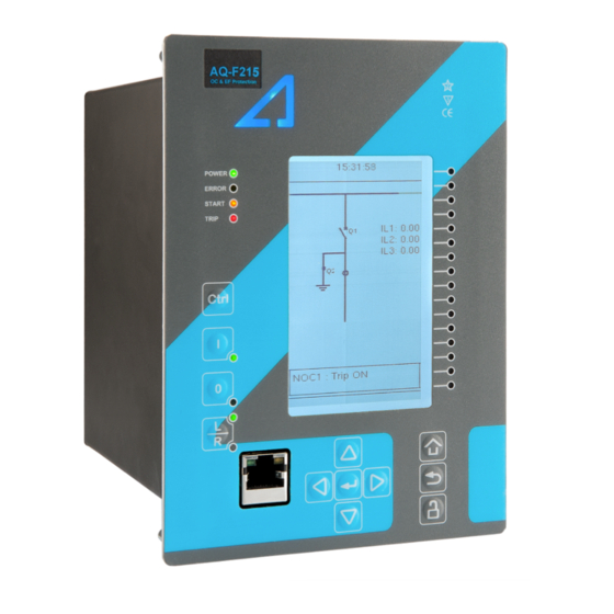
Arcteq AQ-F215 Instruction Manual
Feeder protection ied
Hide thumbs
Also See for AQ-F215:
- Instruction manual (546 pages) ,
- User manual (26 pages) ,
- Instruction manual (380 pages)
Table of Contents
Advertisement
Quick Links
Advertisement
Table of Contents

Related Manuals for Arcteq AQ-F215


Summary of Contents for Arcteq AQ-F215
- Page 1 AQ-F215 Feeder protection IED Instruction manual...
-
Page 2: Table Of Contents
4.9 Configuring user levels and their passwords................. 52 5 Functions unctions ...................................................... 55 5.1 Functions included in AQ-F215.................... 55 5.2 Measurements........................57 5.2.1 Current measurement and scaling ................57 5.2.2 Voltage measurement and scaling ................71 5.2.3 Power and energy calculation ..................82 5.2.4 Frequency tracking and scaling ................. - Page 3 7 Connections and applic 7 Connections and applica a tion examples tion examples..................................421 7.1 Connections of AQ-F215 ....................421 7.2 Application example and its connections................423 7.3 Two-phase, three-wire ARON input connection ..............424 7.4 Trip circuit supervision (95) ....................425...
- Page 4 A A Q Q -F215 -F215 Instruction manual Version: 2.04 9.1.1.3 Power and energy measurement..............454 9.1.1.4 Frequency measurement ................454 9.1.2 CPU & Power supply ....................454 9.1.2.1 Auxiliary voltage..................454 9.1.2.2 CPU communication ports................455 9.1.2.3 CPU digital inputs ..................456 9.1.2.4 CPU digital outputs..................
- Page 5 A A Q Q -F215 -F215 Instruction manual Version: 2.04 10 Or 10 Ordering inf dering informa ormation tion ............................................486 11 Contact and r 11 Contact and re e f f er erence inf ence informa ormation tion....................................
- Page 6 Nothing contained in this document shall increase the liability or extend the warranty obligations of the manufacturer Arcteq Relays Ltd. The manufacturer expressly disclaims any and all liability for any damages and/or losses caused due to a failure to comply with the instructions contained herein or caused by persons who do not fulfil the aforementioned requirements.
- Page 7 A A Q Q -F215 -F215 Instruction manual Version: 2.04 Copyright Copyright © Arcteq Relays Ltd. 2021. All rights reserved.
-
Page 8: Document Inf
A A Q Q -F215 -F215 Instruction manual Version: 2.04 1 Document information 1.1 Version 2 revision notes Table. 1.1 - 1. Version 2 revision notes Revision 2.00 Date 6.6.2019 - New more consistent look. - Improved descriptions generally in many chapters. - Improved readability of a lot of drawings and images. - Page 9 - Improvements to many drawings and formula images. - Improved and updated IED user interface display images. - AQ-F215 Functions included list Added: Voltage memory, U0> recloser, vector jump protection, indicator object, programmable control switch, mA output control and measurement recorder.
-
Page 10: Version 1 Revision Notes
Table. 1.2 - 2. Version 1 revision notes Revision 1.00 Date 8.4.2013 Changes - The first revision for AQ-F215 IED. Revision 1.01 Date 22.11.2013 Application example for ARON input connection added to chapter 8.0. Application example for trip circuit supervision. - Page 11 A A Q Q -F215 -F215 Instruction manual Version: 2.04 Revision 1.09 Date 19.1.2017 Added Vector Jump (78) Changes Added indicator object, programmable control switch and programmable stage descriptions Order code Revision 1.10 Date 14.12.2017 Measurement value recorder description ZCT connection added to current measurement description Internal harmonics blocking to I>,I0>,Idir>,I0dir>...
-
Page 12: Abbr Bbre E Via Viations Tions
A A Q Q -F215 -F215 Instruction manual Version: 2.04 2 Abbreviations AI – Analog input AR – Auto-recloser ASDU – Application service data unit AVR – Automatic voltage regulator BCD – Binary-coded decimal CB – Circuit breaker CBFP – Circuit breaker failure protection CLPU –... - Page 13 A A Q Q -F215 -F215 Instruction manual Version: 2.04 IGBT – Insulated-gate bipolar transistor I/O – Input and output IRIG-B – Inter-range instruction group, timecode B LCD – Liquid-crystal display LED – Light emitting diode LV – Low voltage NC –...
-
Page 14: General
Version: 2.04 3 General The AQ-F215 feeder protection IED is a member of the AQ-200 product line. The hardware and software are modular: the hardware modules are assembled and configured according to the application's I/O requirements and the software determines the available functions. This manual describes the specific application of the AQ-F215 feeder protection IED. -
Page 15: Ied User Interface Erface
A A Q Q -F215 -F215 Instruction manual Version: 2.04 4 IED user interface 4.1 Panel structure The user interface section of an AQ-200 series device is divided into two user interface sections: one for the hardware and the other for the software. You can access the software interface either through the front panel or through the AQtivate freeware software suite. -
Page 16: Mimic And Main Menu
A A Q Q -F215 -F215 Instruction manual Version: 2.04 The sixteen freely configurable LEDs are located on the right side of the display. Their activation and color (green or yellow) are based on the settings the user has put in place in the software. Holding the I I (object control) button down for five seconds brings up the button test menu. -
Page 17: General Menu
A A Q Q -F215 -F215 Instruction manual Version: 2.04 • Control • Communication • Measurement • Monitoring. They are presented in the image below. The available menus vary according to the device type. Figure. 4.2.2 - 3. Main configuration menus. 4.3 General menu The General main menu is divided into two submenus: the Device info tab presents the information of the device, while the Function comments tab allows you to view all comments you have added to the... - Page 18 A A Q Q -F215 -F215 Instruction manual Version: 2.04 Device info Figure. 4.3 - 5. Device info. Table. 4.3 - 3. Parameters and indications in the General menu. Name Range Step Default Description Device name Unitname The file name uses these fields when loading the .aqs configuration file from the AQ-200 unit.
- Page 19 A A Q Q -F215 -F215 Instruction manual Version: 2.04 Name Range Step Default Description 0: User defined 1: English 2: Finnish Changes the language of the parameter descriptions in 3: Swedish the HMI. If the language has been set to "Other" in the Language 4: Spanish 1: English...
-
Page 20: Protection Menu
A A Q Q -F215 -F215 Instruction manual Version: 2.04 Figure. 4.3 - 6. Function comments. 4.4 Protection menu General Figure. 4.4 - 7. Protection menu structure The Protection main menu includes the Stage activation submenu as well as the submenus for all the various protection functions, categorized under the following modules: "Arc protection", "Current", "Voltage", "Frequency", "Sequence"... - Page 21 A A Q Q -F215 -F215 Instruction manual Version: 2.04 Figure. 4.4 - 8. Protection menu view. Stage activation You can activate the various protection stages in the Stage activation submenu (see the images below). Each protection stage and supporting function is disabled by default. When you activate one of the stages, its activated menu appears in the stage-specific submenu.
- Page 22 A A Q Q -F215 -F215 Instruction manual Version: 2.04 Example of a protection stage and its use Once a protection stage has been activated in the Stage activation submenu, you can open its own submenu. In the image series below, the user has activated three current stages. The user accesses the list of activated current stages through the "Current"...
- Page 23 A A Q Q -F215 -F215 Instruction manual Version: 2.04 • Function condition: indicates the stage's condition which can be Normal, Start, Trip, or Blocked. • Expected operating time: Expected time delay from detecting a fault to tripping the breaker. This value can vary during a fault if an inverse curve time delay (IDMT) is used.
- Page 24 A A Q Q -F215 -F215 Instruction manual Version: 2.04 Figure. 4.4 - 13. Registers. Register menu content is not available in the HMI. It can only be accessed with AQtivate setting tool. Stored in the "Registers" section you can find both "Operation event register" and "General event register".
- Page 25 A A Q Q -F215 -F215 Instruction manual Version: 2.04 Figure. 4.4 - 14. I/O. The "I/O" section is divided into two subsections: "Direct output control" and "Blocking input control". In "Direct output control" you can connect the stage's signals to physical outputs, either to an output relay or an LED (START or TRIP LEDs or one of the 16 user configurable LEDs).
-
Page 26: Control Menu
A A Q Q -F215 -F215 Instruction manual Version: 2.04 Figure. 4.4 - 15. Events. You can mask on and mask off the protection stage related events in "Event mask". By default events are masked off. You can activate the desired events by masking them ("x"). Remember to save your maskings by confirming the changes with the check mark icon. - Page 27 A A Q Q -F215 -F215 Instruction manual Version: 2.04 Controls enabled Figure. 4.5 - 16. Controls enabled submenu. You can activate the selected control functions in the Controls enabled submenu. By default all the control functions are disabled. All activated functions can be viewed in the Control functions submenu (see the section "Control functions"...
- Page 28 A A Q Q -F215 -F215 Instruction manual Version: 2.04 • SG loc SG local select al select: selects the local control for the different setting groups (can use digital inputs, logical inputs or outputs, RTDs, object status information as well as stage starts, trips or blocks).
- Page 29 A A Q Q -F215 -F215 Instruction manual Version: 2.04 Figure. 4.5 - 20. Settings section. OBJECT SET AND STATUS • L L oc ocal/R al/Remo emot t e sta e stat t us us: control access may be set to Local or Remote (Local by default; please note that when local control is enabled, the object cannot be controlled through the bus and vice versa).
- Page 30 A A Q Q -F215 -F215 Instruction manual Version: 2.04 • An object has both Open input Open input and C C lose input lose input signals which are used for indicating the status of the breaker on the HMI and in SCADA. Status can be indicated by any of the following: digital inputs, logical inputs or outputs.
- Page 31 A A Q Q -F215 -F215 Instruction manual Version: 2.04 Figure. 4.5 - 21. Application control section. You can connect object statuses directly to specific physical outputs in the "Signal connections" subsection ( Control → Application control ). A status can be connected to output relays, as well as to user-configurable LEDs.
- Page 32 A A Q Q -F215 -F215 Instruction manual Version: 2.04 The "Registers"section stores the function's specific fault data. There are twelve (12) registers, and each of them includes data such as opening and closing times, command types and request failures. The data included in the register depend on the protection function.
- Page 33 A A Q Q -F215 -F215 Instruction manual Version: 2.04 Each control function that has been activated is listed in the Control functions submenu (see the middle image above). This submenu includes the following sections: "Info", "Settings", "Registers", "I/O" and "Events".
- Page 34 A A Q Q -F215 -F215 Instruction manual Version: 2.04 The stage settings vary depending on which control function they are a part of. By default only one setting group of the eight available setting groups is activated. You can enable more groups in the Control →...
- Page 35 A A Q Q -F215 -F215 Instruction manual Version: 2.04 Figure. 4.5 - 28. I/O section. The "I/O" section is divided into two subsections: "Direct output control" and "Blocking input control". In "Direct output control" you can connect the stage's signals to physical outputs, either to an output relay or an LED (START or TRIP LEDs or one of the 16 user configurable LEDs).
- Page 36 A A Q Q -F215 -F215 Instruction manual Version: 2.04 Figure. 4.5 - 29. Events section. You can mask on and mask off events related to an object's stage in "Event mask". By default all events are masked off. You can activate the desired events by masking them ("x"). Please remember to save your maskings by confirming the changes with the check mark icon.
- Page 37 A A Q Q -F215 -F215 Instruction manual Version: 2.04 Figure. 4.5 - 31. Digital input section. All settings related to digital inputs can be found in the "Digital inputs" section. The "Digital inputs settings" subsection includes various settings for the inputs: the polarity selection determines whether the input is Normal Open (NO) or Normal Closed (NC) as well as the activation threshold voltage (16…200 V AC/DC, step 0.1 V) and release threshold voltage (10…200 V AC/DC, step 0.1 V) for each available input.
- Page 38 A A Q Q -F215 -F215 Instruction manual Version: 2.04 The "Digital outputs settings" subsection lets you select the polarity for each output; they can be either Normal Open (NO) or Normal Closed (NC). The default polarity is Normal Open. The operational delay of an output contact is approximately 5 ms.
- Page 39 A A Q Q -F215 -F215 Instruction manual Version: 2.04 Figure. 4.5 - 34. Device I/O matrix section. Through the "Device I/O matrix" section you can connect digital inputs, logical outputs, protection stage status signals (START, TRIP, BLOCKED, etc.), object status signals and many other binary signals to output relays, or to LEDs configured by the used.
- Page 40 A A Q Q -F215 -F215 Instruction manual Version: 2.04 Figure. 4.5 - 36. Programmable mimic indicators section Programmable mimic indicators can be placed into the mimic to display a text based on the status of a given binary signal (digital input, logical signal, status of function start/tripped/blocked signals etc.). When configuring the mimic with the AQtivate setting tool, it is possible to set a text to be shown when an input signal is ON and a separate text for when the signal is OFF.
-
Page 41: Communication Menu
A A Q Q -F215 -F215 Instruction manual Version: 2.04 GOOSE inputs are mainly used for controlling purposes and in conjunction with the IEC 61850 communication protocol. There are 64 GOOSE inputs signal status bits, and their status can be either 0 or 1. - Page 42 A A Q Q -F215 -F215 Instruction manual Version: 2.04 Connections Figure. 4.6 - 38. View of the Connections submenu. The Connections submenu offers the following bits of information and settings: ETHERNET ETHERNET This section defines the IP settings for the ethernet port in the back panel of the unit. •...
- Page 43 A A Q Q -F215 -F215 Instruction manual Version: 2.04 Protocols Figure. 4.6 - 39. View of the Protocols submenu. The Protocols submenu offers access to the various communication protocol configuration menus. Some of the communication protocols use serial communication and some use Ethernet communication.
-
Page 44: Measurement Menu
A A Q Q -F215 -F215 Instruction manual Version: 2.04 4.7 Measurement menu Figure. 4.7 - 40. Measurement section. The Measurement menu includes the following submenus: Transformers , Frequency , Current measurement , Voltage measurement , Power and energy measurement , Impedance calculations , and Phasors . - Page 45 A A Q Q -F215 -F215 Instruction manual Version: 2.04 CT module Figure. 4.7 - 42. CT module section. The three main sections ("Phase CT scaling", "Residual I01 CT scaling" and "Residual I02 CT scaling") determine the ratio of the used transformers. Additionally, the nominal values are also determined in the CT module submenu.
- Page 46 A A Q Q -F215 -F215 Instruction manual Version: 2.04 VT primary and secondary voltages must match with the connected voltage transformer in addition to the voltage measurement mode. These settings are then used for scaling the voltage channel input voltages to primary and per unit values as well as power and energy measurement values if current measurements are also available.
- Page 47 A A Q Q -F215 -F215 Instruction manual Version: 2.04 Current measurement Figure. 4.7 - 45. Current measurement submenu. Current measurement submenu includes various individual measurements for each phase or phase-to- phase measurement. The Current measurement submenu has been divided into four sections: "Phase currents", "Residual currents", "Sequence currents", and "Harmonics".
- Page 48 A A Q Q -F215 -F215 Instruction manual Version: 2.04 Voltage measurement Figure. 4.7 - 46. Voltage measurement submenu and System Voltages menu. Voltage measurement submenu includes various individual measurements for each phase or phase-to- phase measurement. The Voltage measurement submenu has been also divided into four sections: "Voltage inputs", "Sequence voltages", "System voltages", and "Harmonics".
- Page 49 A A Q Q -F215 -F215 Instruction manual Version: 2.04 Power and energy measurement Figure. 4.7 - 47. Power and Energy measurement submenu. The Power and energy measurement submenu includes three sections: "Power and energy measurement settings", "Power measurements" and "Energy measurements". As the name suggests, the first section determines the settings by which the power and energy calculations are made.
-
Page 50: Monitoring Menu
A A Q Q -F215 -F215 Instruction manual Version: 2.04 The Impedance calculations submenu is divided into four sections: "Impedance calculation settings", "Phase-to-phase impedances", "Phase-to-earth impedances" and "Positive sequence impedance". You can activate impedance calculations in the first section. "Phase-to-phase impedances" display the resistances and reactances of the three phase-to-phase connections, both primary and secondary, as well as the primary and secondary impedances and impedance angles. - Page 51 A A Q Q -F215 -F215 Instruction manual Version: 2.04 Monitors enabled Figure. 4.8 - 51. Monitors enabled submenu. You can activate the selected monitor functions in the Monitors enabled submenu. By default all the control functions are disabled. All activated functions can be viewed in the Monitor functions submenu (see the section "Monitor functions"...
- Page 52 A A Q Q -F215 -F215 Instruction manual Version: 2.04 Disturbance recorder Figure. 4.8 - 53. Disturbance recorder settings. The Disturbance recorder submenu has the following settings: • "Recorder enabled" enables or disables the recorder. • "Recorder status" indicates the status of the recorder. •...
-
Page 53: Configuring User Levels And Their Passwords
A A Q Q -F215 -F215 Instruction manual Version: 2.04 • Enabling "Auto. get recordings" allows the device to automatically upload recordings to the designated FTP folder (which, in turn, allows any FTP client to read the recordings from the IED's memory). - Page 54 A A Q Q -F215 -F215 Instruction manual Version: 2.04 • Super user (***) • Configurator (**) • Operator (*) • User ( - ) You can set a new password for a user level by selecting the key icon next to the user level's name. After this you can lock the user level by pressing the R R e e t t urn urn key while the lock is selected.
- Page 55 A A Q Q -F215 -F215 Instruction manual Version: 2.04 • Configurator: Can change most settings such as basic protection pick-up levels or time delays, breaker control functions, signal descriptions etc. and can operate breakers and other equipment. • Super user: Can change any setting and can operate breakers and other equipment. NOTE! Any user level with a password automatically locks itself after half an hour (30 minutes) of inactivity.
-
Page 56: Functions Unctions
Instruction manual Version: 2.04 5 Functions 5.1 Functions included in AQ-F215 The AQ-F215 feeder protection relay includes the following functions as well as the number of stages for those functions. Table. 5.1 - 4. Protection functions of AQ-F215. Name (number... - Page 57 RPW (1) Reverse power protection VMEM (1) Voltage memory ARC (1) IArc>/I0Arc> 50Arc/50NArc Arc fault protection (optional) Table. 5.1 - 5. Control functions of AQ-F215. Name ANSI Description Setting group selection Object control and monitoring (5 objects available) Indicator object monitoring...
-
Page 58: Measurements
A A Q Q -F215 -F215 Instruction manual Version: 2.04 Name ANSI Description 21FL Fault locator Measurement recorder VREC Measurement value recorder 5.2 Measurements 5.2.1 Current measurement and scaling The current measurement module (CT module, or CTM) is used for measuring the currents from current transformers. - Page 59 A A Q Q -F215 -F215 Instruction manual Version: 2.04 SEC: SEC: The secondary current, i.e. the current which the current transformer transforms according to its ratios. This current is measured by the protection relay. NOM: NOM: The nominal primary current of the protected object. For the measurements to be correct the user needs to ensure that the measurement signals are connected to the correct inputs, that the current direction is connected to the correct polarity, and that the scaling is set according to the nominal values of the current transformer.
- Page 60 A A Q Q -F215 -F215 Instruction manual Version: 2.04 The following table presents the initial data of the connection. Table. 5.2.1 - 7. Initial data. P P ha hase curr se current C ent CT T R R ing cor ing core C e CT in Input I02 T in Input I02...
- Page 61 A A Q Q -F215 -F215 Instruction manual Version: 2.04 Figure. 5.2.1 - 58. Setting the phase current transformer scalings to the protected object's nominal current. Once the measurement scaling is tied to the protected object's nominal current, the user must set the appropriate input for the "Nominal current In"...
- Page 62 A A Q Q -F215 -F215 Instruction manual Version: 2.04 Figure. 5.2.1 - 60. Residual I02 CT scaling (sensitive). Displaying the scaling Depending on whether the scaling was done based on the CT primary values or the protected object's nominal current, the measurements are displayed slightly differently. The first of the two images shows how the measurements are displayed when the CT primary values are the basis for the scaling;...
- Page 63 A A Q Q -F215 -F215 Instruction manual Version: 2.04 Example of zero sequence CT scaling Zero sequence CT scaling (ZCT scaling) is done when a zero sequence CT instead of a ring core CT is part of the measurement connection. In such a case the zero sequence CT should be connected to the I02 channel which has lower CT scaling ranges (see the image below).
- Page 64 A A Q Q -F215 -F215 Instruction manual Version: 2.04 Problem Solution The phase currents are connected to the measurement module but the order or polarity of one or all phases is incorrect. In relay settings, go to Measurement → Phasors and check the "Phase current vectors"...
- Page 65 A A Q Q -F215 -F215 Instruction manual Version: 2.04 Figure. 5.2.1 - 64. Common phase polarity problems. The following image presents the most common problems with network rotation (mix phases). These problems can be difficult to find because the measurement result is always the same in the relay. If two phases are mixed together, the network rotation always follows the pattern IL1-IL3-IL2 and the measured negative sequence current is therefore always 1.00 (in.
- Page 66 A A Q Q -F215 -F215 Instruction manual Version: 2.04 Figure. 5.2.1 - 65. Common network rotation (mixed phases) problems. Settings Table. 5.2.1 - 8. Settings of the Phase CT scaling. Name Unit Range Step Default Description 0: CT Scale 0: CT The selection of the reference used in the relay's per-unit system nom p.u.
- Page 67 A A Q Q -F215 -F215 Instruction manual Version: 2.04 Table. 5.2.1 - 9. Settings of the Residual I01 CT scaling. Name Unit Range Step Default Description I01 CT 0.2…25 000 0.00001 100 The rated primary current of the current transformer. primary I01 CT 0.1…10.000 0.00001 1...
- Page 68 A A Q Q -F215 -F215 Instruction manual Version: 2.04 Table. 5.2.1 - 13. Secondary phase current measurements. Name Unit Range Step Description Secondary phase The primary RMS current measurement from each of the phase current ILx 0.00…300.00 0.01 current channels. ("Sec.Pha.curr.ILx") Secondary phase current ILx TRMS...
- Page 69 A A Q Q -F215 -F215 Instruction manual Version: 2.04 Table. 5.2.1 - 18. Residual phase angle measurements. Name Unit Range Step Description Residual current angle The residual current angle measurement from the I01 or I02 current 0.00…360.00 0.01 input. ("Res.curr.angle I0x") calc.I0 Pha.angle 0.00…360.00 0.01...
- Page 70 A A Q Q -F215 -F215 Instruction manual Version: 2.04 Table. 5.2.1 - 23. Harmonic current measurements. Name Range Step Default Description Harmonics 0: Percent calculation values Defines whether the harmonics are calculated as percentage or ("Harm Abs.or Percent absolute values. Absolute Perc.") 0: Per unit...
- Page 71 A A Q Q -F215 -F215 Instruction manual Version: 2.04 Name Unit Range Step Description Positive sequence reactive current The reactive current component measurement (in p.u.) from × In -1250.00…1250.00 0.01 ("Pos.Seq Reactive the positive sequence current channel. Current p.u.") Residual resistive current I0x The resistive current component measurement (in p.u.) from...
-
Page 72: Voltage Measurement And Scaling
A A Q Q -F215 -F215 Instruction manual Version: 2.04 Name Unit Range Step Description Secondary reactive current (PSC) The secondary reactive current component measurement from -300.00…300.00 0.01 ("Pos.Seq Reactive the positive sequence current channel. Current Sec.") Secondary residual resistive current The secondary resistive current component measurement from -300.00…300.00 0.01 ("I0x Resistive Current... - Page 73 A A Q Q -F215 -F215 Instruction manual Version: 2.04 Normally, the primary line-to-line voltage rating for VTs is 400 V...60 kV, while the secondary voltage ratings are 100 V...210 V. Non-standard ratings can also be directly connected as the scaling settings are flexible and have large ranges.
- Page 74 A A Q Q -F215 -F215 Instruction manual Version: 2.04 Figure. 5.2.2 - 68. Selecting the measured magnitude. Voltage protection itself is based on the nominal voltage. A 20 000 V nominal voltage equals a 100 % setting in voltage-based protection functions. A 120 % trip setting in the overvoltage stage equals to 24 000 V on the primary level (in this case a 20 % increase equals 4000 V).
- Page 75 A A Q Q -F215 -F215 Instruction manual Version: 2.04 • 3LN+U4 (three line-to-neutral voltages and U4 can be used for either zero sequence voltage or synchrochecking) • 3LL+U4 (three line-to-line voltages and U4 can be used either for zero sequence voltage or synchrochecking) •...
- Page 76 A A Q Q -F215 -F215 Instruction manual Version: 2.04 Figure. 5.2.2 - 71. 2LL+U0+SS settings and connections. The image collection below presents the relay's behavior when nominal voltage is injected into the relay via secondary test equipment. The measurement mode is 3LN+U4 which means that the relay is measuring line-to-neutral voltages.
- Page 77 A A Q Q -F215 -F215 Instruction manual Version: 2.04 Figure. 5.2.2 - 73. Relay behavior when voltage injected during an earth fault. Troubleshooting When the measured voltage values differ from the expected voltage values, the following table offers possible solutions for the problems. Problem Check / Resolution The measured...
- Page 78 A A Q Q -F215 -F215 Instruction manual Version: 2.04 Name Range Step Default Description The voltage channel U3 can be used to measure zero sequence voltage 0: Not Used 0: Not U3 mode U0 (U0) or the Synchrocheck voltage (SS). If neither is needed, the (default) 1: U0 Used or SS...
- Page 79 A A Q Q -F215 -F215 Instruction manual Version: 2.04 Name Range Step Default Description VT scaling A relay feedback value; the calculated scaling factor that is the ratio factor P/S between the primary voltage and the secondary voltage. VT scaling A relay feedback value;...
- Page 80 A A Q Q -F215 -F215 Instruction manual Version: 2.04 Table. 5.2.2 - 32. Per-unit sequence voltage measurements. Name Unit Range Step Description Positive sequence The measurement (in p.u.) from the calculated positive sequence × U voltage 0.00…500.0 0.01 voltage. ("Pos.seq.Volt.p.u.") Negative sequence The measurement (in p.u.) from the calculated negative sequence...
- Page 81 A A Q Q -F215 -F215 Instruction manual Version: 2.04 Table. 5.2.2 - 36. System primary voltage measurements. Name Unit Range Step Description System voltage magnitude 0.00…1 The primary RMS line-to-line UL12 voltage (measured or calculated). You can also UL12 0.01 000000.00 select the row where the unit for this is kV.
- Page 82 A A Q Q -F215 -F215 Instruction manual Version: 2.04 Name Unit Range Step Description System voltage magnitude The primary measured RMS Synchrocheck voltage (SS). This magnitude is 0.00…1 0.01 displayed only when the "2LL+U3+U4" mode is selected and both U3 and U4 are in 000000.00 ("System use.
-
Page 83: Power And Energy Calculation
A A Q Q -F215 -F215 Instruction manual Version: 2.04 Table. 5.2.2 - 38. Harmonic voltage measurements. Name Unit Range Step Default Description Harmonics calculation values 0: Percent Defines whether the harmonics are calculated as ("Harm Abs.or 1: Absolute Percent percentages or absolute values. - Page 84 A A Q Q -F215 -F215 Instruction manual Version: 2.04 Figure. 5.2.3 - 75. Three-phase active power (P) calculation. In these equations, phi (φ) is the angle difference between voltage and current. Figure. 5.2.3 - 76. Three-phase reactive power (Q) calculation. Active power can be to the forward or the reverse direction.
- Page 85 A A Q Q -F215 -F215 Instruction manual Version: 2.04 Only line y line-t -to-line v o-line volta oltages a ges av v ailable ailable If the line-to-line voltages are measured but the zero sequence voltage is not measured or is not otherwise known, the three-phase power calculation is based on Aron’s theorem: Both cos(φ) and tan(φ) are calculated in the same way as in the line-to-neutral mode.
- Page 86 A A Q Q -F215 -F215 Instruction manual Version: 2.04 Name Range Step Default Description 0: Undefined 1: Q1 Fwd Ind PQ Quadrant 2: Q2 Rev Cap Indicates what the power PQ quadrant is at that moment. Undefined 3: Q3 Rev Ind 4: Q4 Fwd Cap 0: Undefined 1: Q1 Fwd Cap AV...
- Page 87 A A Q Q -F215 -F215 Instruction manual Version: 2.04 Name Range Step Default Description DC1…4 Pulses 0…4 294 967 295 Indicates the total number of pulses sent. sent Table. 5.2.3 - 41. DC 1…4 Pulse out settings Name Range Step Default Description...
- Page 88 A A Q Q -F215 -F215 Instruction manual Version: 2.04 Table. 5.2.3 - 44. Three-phase energy calculations. Name Range Step Description -999 999 995 Exported Active Energy (P) (kWh 904.00…999 999 995 0.01 The total amount of exported active energy. or MWh) 904.00 -999 999 995...
- Page 89 A A Q Q -F215 -F215 Instruction manual Version: 2.04 Name Range Step Description Reactive energy (Q) balance while The sum of the phase's imported and exported reactive 0.01 -1x10 …1x10 Import (P) Lx (kVarh or MVarh) energy while active energy is imported. The apparent energy of the phase while active energy is Apparent Energy (S) while Export (P) Lx 0.01...
-
Page 90: Frequency Tracking And Scaling
A A Q Q -F215 -F215 Instruction manual Version: 2.04 Voltages (line-to-line): Currents: = 100.00 V, -90.00° = 2.5 A, -120.00° = 2.5 A, 120.00° Name Values 3PH (S) 20.00 MVA 3PH (P) 17.32 MW 3PH (Q) 0.00 Mvar 3PH Tan 0.00 3PH Cos 0.87... - Page 91 FFT calculation always has a whole power cycle in the buffer. The measurement accuracy is further improved by Arcteq's patented calibration algorithms that calibrate the analog channels against eight (8) system frequency points for both magnitude and angle.
- Page 92 A A Q Q -F215 -F215 Instruction manual Version: 2.04 Name Range Step Default Description System The user-defined system nominal frequency that is used when nominal 7.000…75.000Hz 0.001Hz 50Hz the "Sampling mode" setting has been set to "Fixed". frequency Tracked system 0.000…75.000Hz 0.001Hz Displays the rough measured system frequency.
-
Page 93: Protection Functions
A A Q Q -F215 -F215 Instruction manual Version: 2.04 Name Range Step Default Description Tracked f Displays the rough value of the tracked frequency in Channel 0.000…75.000Hz 0.001Hz - channel C Frequency measurement built from tracked frequencies and Alg f fast 0.000…75.000Hz 0.001Hz - U4 voltage channel samples. - Page 94 A A Q Q -F215 -F215 Instruction manual Version: 2.04 The protection function is run in a completely digital environment with a protection CPU microprocessor which also processes the analog signals transformed into the digital form.
- Page 95 A A Q Q -F215 -F215 Instruction manual Version: 2.04 Figure. 5.3.1 - 77. Principle diagram of the protection relay platform. In the following chapters the common functionalities of protection functions are described. If a protection function deviates from this basic structure, the difference is described in the corresponding chapter of the manual.
- Page 96 A A Q Q -F215 -F215 Instruction manual Version: 2.04 Figure. 5.3.1 - 79. Measurement range in relation to the nominal current. The I magnitude refers to the user set nominal current which can range from 0.2…10 A, typically 0.2 A, 1A or 5 A.
- Page 97 A A Q Q -F215 -F215 Instruction manual Version: 2.04 • Inverse definite minimum time (IDMT): activates the trip signal after a time which is in relation to the set pick-up value X and the measured value X (dependent time characteristics). Both IEC and IEEE/ANSI standard characteristics as well as user settable parameters are available for the IDMT operation.
- Page 98 A A Q Q -F215 -F215 Instruction manual Version: 2.04 Name Range Step Default Description Selects the IEC standard delay characteristics. The options include the following: Normally Inverse ("NI"), 0: NI Extremely Inverse ("EI"), Very Inverse ("VI") and Long Time Inverse Delay 1: EI ("LTI") characteristics.
- Page 99 A A Q Q -F215 -F215 Instruction manual Version: 2.04 Figure. 5.3.1 - 81. Inverse operating time formulas for IEC and IEEE standards. Non-standard delay characteristics In addition to the previously mentioned delay characteristics, some functions also have delay characteristics that deviate from the IEC or IEEE standards. These functions are the following: •...
- Page 100 A A Q Q -F215 -F215 Instruction manual Version: 2.04 Table. 5.3.1 - 50. Setting parameters for reset time characteristics. Name Name Range Range St Step Defa fault ult Descrip Description tion Delayed Resetting characteristics selection (either time-delayed or instant) after 0: No pick-up 1: Yes...
- Page 101 A A Q Q -F215 -F215 Instruction manual Version: 2.04 Figure. 5.3.1 - 83. Delayed pick-up release, delay counter is reset at signal drop-off. Figure. 5.3.1 - 84. Delayed pick-up release, delay counter value is held during the release time.
-
Page 102: Non-Directional Overcurrent Protection (I>; 50/51)
A A Q Q -F215 -F215 Instruction manual Version: 2.04 Figure. 5.3.1 - 85. Delayed pick-up release, delay counter value is decreasing during the release time. The resetting characteristics can be set according to the application. The default setting is delayed 60 ms and the time calculation is held during the release time. - Page 103 A A Q Q -F215 -F215 Instruction manual Version: 2.04 The outputs of the function are the START, TRIP and BLOCKED signals. The non- directional overcurrent function uses a total of eight (8) separate setting groups which can be selected from one common source.
- Page 104 A A Q Q -F215 -F215 Instruction manual Version: 2.04 Measured input The function block uses analog current measurement values. However, when the peak-to-peak mode is selected for the function's "Measured magnitude" setting , the values are taken directly from the samples.
- Page 105 A A Q Q -F215 -F215 Instruction manual Version: 2.04 Table. 5.3.2 - 53. Pick-up settings. Name Description Range Step Default Pick-up setting 0.10…50.00×I 0.01×I 1.20×I The pick-up activation of the function is not directly equal to the START signal generation of the function.
- Page 106 A A Q Q -F215 -F215 Instruction manual Version: 2.04 Table. 5.3.2 - 55. Internal inrush harmonic blocking settings. Name Range Step Default Description Inrush harmonic blocking (internal- 0: No Enables and disables the 2 harmonic 0: No only trip) 1: Yes blocking.
- Page 107 A A Q Q -F215 -F215 Instruction manual Version: 2.04 Event number Event channel Event block name Event code Description 1291 NOC1 Phase C Start OFF 1292 NOC1 Phase A Trip ON 1293 NOC1 Phase A Trip OFF 1294 NOC1 Phase B Trip ON 1295 NOC1...
- Page 108 A A Q Q -F215 -F215 Instruction manual Version: 2.04 Event number Event channel Event block name Event code Description 1421 NOC3 Phase A Trip OFF 1422 NOC3 Phase B Trip ON 1423 NOC3 Phase B Trip OFF 1424 NOC3 Phase C Trip ON 1425 NOC3...
-
Page 109: Non-Directional Earth Fault Protection (I0>; 50N/51N)
A A Q Q -F215 -F215 Instruction manual Version: 2.04 5.3.3 Non-directional earth fault protection (I0>; 50N/51N) The non-directional earth fault function is used for instant and time-delayed earth fault protection. The number of stages in the function depend on the device model. The operating characteristics are based on the selected neutral current magnitudes which the function measures constantly. - Page 110 A A Q Q -F215 -F215 Instruction manual Version: 2.04 Figure. 5.3.3 - 87. Simplified function block diagram of the I0> fucntion. Measured input The function block uses analog current measurement values. The user can select the monitored magnitude to be equal either to RMS values, to TRMS values, or to peak-to-peak values. TRMS mode uses values from the whole harmonic spectrum of 32 components.
- Page 111 A A Q Q -F215 -F215 Instruction manual Version: 2.04 Name Description Range Default 1: RMS Measured Defines which available measured magnitude is used by the function. This 2: TRMS 1: RMS magnitude parameter is available when "Input selection" has been set to "I01" or "I02". 3: Peak- to-peak 1: I01...
- Page 112 A A Q Q -F215 -F215 Instruction manual Version: 2.04 Name Range Step Description meas at the 0.00...1250.00 0.01 The ratio between the measured current and the pick-up value. moment Function blocking The block signal is checked in the beginning of each program cycle. The blocking signal is received from the blocking matrix in the function's dedicated input.
-
Page 113: Directional Overcurrent Protection (Idir>; 67)
A A Q Q -F215 -F215 Instruction manual Version: 2.04 Event number Event channel Event block name Event code Description 1666 NEF1 Trip ON 1667 NEF1 Trip OFF 1668 NEF1 Block ON 1669 NEF1 Block OFF 1728 NEF2 Start ON 1729 NEF2 Start OFF... - Page 114 A A Q Q -F215 -F215 Instruction manual Version: 2.04 The outputs of the function are the START, TRIP and BLOCKED signals. The directional overcurrent function uses a total of eight (8) separate setting groups which can be selected from one common source.
- Page 115 A A Q Q -F215 -F215 Instruction manual Version: 2.04 Measured input The function block uses analog current measurement values. The user can select the monitored magnitude to be equal either to RMS values, to TRMS values, or to peak-to-peak values. TRMS mode uses values from the whole harmonic spectrum of 32 components.
- Page 116 A A Q Q -F215 -F215 Instruction manual Version: 2.04 Pick-up The I setting parameter controls the pick-up of the I> function. This defines the maximum allowed measured current before action from the function. The function constantly calculates the ratio between the I and the measured magnitude ( I ) for each of the three phases.
- Page 117 A A Q Q -F215 -F215 Instruction manual Version: 2.04 Please note in the picture above that the tripping area is linked to the angle of the positive sequence voltage U . The angle of the positive sequence current I is compared to U angle, and if the fault is in the correct direction, it is possible to perform a trip when the amplitude of I...
- Page 118 A A Q Q -F215 -F215 Instruction manual Version: 2.04 Figure. 5.3.4 - 91. When Idir> function has been set to "Non-directional" the function works basically just like a traditional non- directional overcurrent protection function. Read-only parameters The relay's Info page displays useful, real-time information on the state of the protection function. It is accessed either through the relay's HMI display, or through the setting tool software when it is connected to the relay and its Live Edit mode is active.
- Page 119 A A Q Q -F215 -F215 Instruction manual Version: 2.04 Function blocking The block signal is checked in the beginning of each program cycle. The blocking signal is received from the blocking matrix in the function's dedicated input. Additionally, the non-directional overcurrent function includes an internal inrush harmonic blocking option which is applied according to the parameters set by the user.
- Page 120 A A Q Q -F215 -F215 Instruction manual Version: 2.04 Event Number Event channel Event block name Event Code Description 4805 DOC1 Block OFF 4806 DOC1 No voltage, Blocking ON 4807 DOC1 Voltage measurable, Blocking OFF 4808 DOC1 Measuring live angle ON 4809 DOC1 Measuring live angle OFF...
-
Page 121: Directional Earth Fault Protection (I0Dir>; 67N/32N)
A A Q Q -F215 -F215 Instruction manual Version: 2.04 Event Number Event channel Event block name Event Code Description 4999 DOC4 Voltage measurable, Blocking OFF 5000 DOC4 Measuring live angle ON 5001 DOC4 Measuring live angle OFF 5002 DOC4 Using voltmem ON 5003 DOC4... - Page 122 A A Q Q -F215 -F215 Instruction manual Version: 2.04 • threshold comparator • angle check • block signal check • time delay characteristics • output processing. The inputs for the function are the following: • operating mode selections • setting parameters •...
- Page 123 A A Q Q -F215 -F215 Instruction manual Version: 2.04 Table. 5.3.5 - 72. Measurement inputs of the I0dir> function. Signal Description Time base I01RMS RMS measurement of coarse residual current measurement input I01 I01TRMS TRMS measurement of coarse residual current measurement input I01 I01PP Peak-to-peak measurement of coarse residual current measurement input I01 I02RMS...
- Page 124 A A Q Q -F215 -F215 Instruction manual Version: 2.04 Table. 5.3.5 - 74. Pick-up settings. Name Description Range Step Default Pick-up setting 0.005…40.00×I 0.001×I 1.20×I 1…75%U 0.01%U 20%U Pick-up setting 1: Unearthed [32N Var] 2: Petersen coil GND [32N Watt] Grounding 3: Grounded Network grounding method...
- Page 125 A A Q Q -F215 -F215 Instruction manual Version: 2.04 Unearthed network Figure. 5.3.5 - 93. Angle tracking of I0dir> function (unearthed network model) (32N) When the unearthed (capacitive) network mode is chosen, the device expects the fault current to be lagging zero sequence voltage by 90 degrees.
- Page 126 A A Q Q -F215 -F215 Instruction manual Version: 2.04 The resistance of the fault affects the size of the voltage drop during a fault. In direct earth fault the zero sequence voltage amplitude is equal to the system's line-to-earth voltage. In direct earth fault the voltage of a faulty phase drops close to zero and healthy phase voltages increase to the amplitude of line-to-line voltages.
- Page 127 A A Q Q -F215 -F215 Instruction manual Version: 2.04 When the Petersen coil earthed (compensated) network mode is chosen, the device expects the fault current to be in the opposite direction to the zero sequence voltage. Healthy phases of both healthy and faulty feeders produce a capacitive current similar to the unearthed network.
- Page 128 A A Q Q -F215 -F215 Instruction manual Version: 2.04 Directly earthed or small impedance network (67N) Figure. 5.3.5 - 95. Angle tracking of I0dir> function (directly earthed or small impedance network). In a directly earthed network the amplitude of a single-phase fault current is similar to the amplitude of a short-circuit current.
- Page 129 CT errors. For all these reasons, Arcteq has developed an improved alternative to these traditional directional earth fault protections.
- Page 130 No extra parameterization is required compared to the traditional method. The multi- criteria algorithm can be tested with COMTRADE files supplied by Arcteq. The function requires a connection of three-phase currents, residual current and residual voltage to operate correctly.
- Page 131 A A Q Q -F215 -F215 Instruction manual Version: 2.04 Name Range Step Description U0> Pick-up 0.0...1 000 000V 0.1V The required residual voltage on the primary side for the relay to trip. setting Detected U0/ The angle in degrees between the monitored residual voltage and the -360.00...360.00deg 0.01deg I0 angle (fi)
- Page 132 A A Q Q -F215 -F215 Instruction manual Version: 2.04 The variables the user can set are binary signals from the system. The blocking signal needs to reach the device minimum of 5 ms before the set operating delay has passed in order for the blocking to activate in time.
- Page 133 A A Q Q -F215 -F215 Instruction manual Version: 2.04 Event number Event channel Event block name Event code Description 5258 DEF2 I0Cosfi Trip ON 5259 DEF2 I0Cosfi Trip OFF 5260 DEF2 I0Sinfi Trip ON 5261 DEF2 I0Sinfi Trip OFF 5312 DEF3 Start ON...
-
Page 134: Intermittent Earth Fault Protection (I0Int>; 67Nt)
A A Q Q -F215 -F215 Instruction manual Version: 2.04 Table. 5.3.5 - 78. Register content. Register Description Event code dd.mm.yyyy hh:mm:ss.mss Date and time 5184-5389 Descr. pre-triggering current Start average current fault current Trip -20ms averages Fault capacity I Trip -20ms averages Fault resist I Trip -20ms averages... - Page 135 A A Q Q -F215 -F215 Instruction manual Version: 2.04 Previously, these scenarios were usually ignored and filed under 'Mysteries of the universe' because they only occured once or twice a year and because disturbance recordings were not commonly used in normal medium-voltage substations for fault verification. However, when disturbance recorders were introduced as a common feature of protection relays this phenomenon received a name and defined characteristics.
- Page 136 A A Q Q -F215 -F215 Instruction manual Version: 2.04 Figure. 5.3.6 - 99. An intermittent earth fault in a network tuned close to resonance, as seen by a healthy feeder relay.
- Page 137 A A Q Q -F215 -F215 Instruction manual Version: 2.04 Figure. 5.3.6 - 100. An intermittent earth fault in an undercompensated medium size network, as seen by a faulty feeder relay.
- Page 138 A A Q Q -F215 -F215 Instruction manual Version: 2.04 Figure. 5.3.6 - 101. Undercompensated medium size network intermittent earth fault seen by healthy feeder relay. As can be seen from the figures above, the residual voltage is high both in the network tuned close to resonance and in the undercompensated network.
- Page 139 A A Q Q -F215 -F215 Instruction manual Version: 2.04 The strike-through time of an intermittent earth fault in a network tuned close to resonance sets the limit for the minimum operating time for an intermittent earth fault protection stage. To ensure a correct protection operation in all cases, the reset time of an intermittent earth fault stage will be set according to the network in question, to such a level that ensures that the fault has disappeared and no new strike-throughs are expected after a prescribed reset time.
- Page 140 A A Q Q -F215 -F215 Instruction manual Version: 2.04 Measured input The function block uses analog current measurement values from the residual magnitudes. The residual voltage has to be measured for this function to operate correctly. Either the I01 or the I02 channel can be selected for residual current samples.
- Page 141 A A Q Q -F215 -F215 Instruction manual Version: 2.04 Table. 5.3.6 - 82. Information displayed by the function. Name Range Step Description 0: Normal 1: StartFWD I0Int> 2: StartREV Displays status of the protection function. condition 3: Trip 4: Blocked U0>...
- Page 142 A A Q Q -F215 -F215 Instruction manual Version: 2.04 Table. 5.3.6 - 83. Operating time characteristics setting parameters. Name Range Step Default Description Forward start detection reset time. Starts to count from the first detected forward (faulty feeder) spike. If while counting another spike is detected, reset 0.000…1800.000s 0.005s 0.300s it resets and starts from the beginning.
-
Page 143: Negative Sequence Overcurrent/ Phase Current Reversal/ Current Unbalance Protection (I2>; 46/46R/46L)
A A Q Q -F215 -F215 Instruction manual Version: 2.04 Table. 5.3.6 - 85. Register content. Setting Date and Event Trip time Started Spikes Started Spikes Spikes to group time code remaining trip in use Set spikes to trip Time YES/ calculated YES/... - Page 144 A A Q Q -F215 -F215 Instruction manual Version: 2.04 The function outputs START, TRIP and BLOCKED signals which can be used for direct I/O controlling and user logic programming. The function generates general time-stamped ON/OFF events to the common event buffer from each of the three (3) output signals. In instant operating mode the function outputs START and TRIP events simultaneously with an equivalent time stamp.
- Page 145 A A Q Q -F215 -F215 Instruction manual Version: 2.04 Name Description Range Step Default Defines whether the ratio between the positive and the negative sequence currents Measured 1: I2pu are supervised or whether only the negative sequence is used in detecting 1: I2pu magnitude 2: I2/I1...
- Page 146 A A Q Q -F215 -F215 Instruction manual Version: 2.04 The variables the user can set are binary signals from the system. The blocking signal needs to reach the device minimum of 5 ms before the set operating delay has passed in order for the blocking to activate in time.
- Page 147 A A Q Q -F215 -F215 Instruction manual Version: 2.04 Figure. 5.3.7 - 103. Operation characteristics curve for I2> Curve2. For a more detailed description on the time characteristics and their setting parameters, please refer to the "General properties of a protection function" chapter and its "Operating time characteristics for trip and reset"...
-
Page 148: Harmonic Overcurrent Protection (Ih>; 50H/51H/68H)
A A Q Q -F215 -F215 Instruction manual Version: 2.04 Event Number Event channel Event block name Event Code Description 2051 CUB1 Trip OFF 2052 CUB1 Block ON 2053 CUB1 Block OFF 2112 CUB2 Start ON 2113 CUB2 Start OFF 2114 CUB2 Trip ON... - Page 149 A A Q Q -F215 -F215 Instruction manual Version: 2.04 The function can operate on instant or time-delayed mode. Either START or TRIP signal can be used when the instant mode is selected to block other protection stages. In time-delayed mode the operation can be selected between definite time (DT) mode and inverse definite minimum time (IDMT) mode.
- Page 150 A A Q Q -F215 -F215 Instruction manual Version: 2.04 Figure. 5.3.8 - 104. Simplified function block diagram of the Ih> function. Measured input The function block uses analog current measurement values from phase or residual currents. Each measurement input of the function block uses RMS values and harmonic components of the selected current input.
- Page 151 A A Q Q -F215 -F215 Instruction manual Version: 2.04 Signal Description Time base The magnitudes (RMS) of phase L2 (B) current components: - Fundamental harmonic harmonic harmonic harmonic harmonic IL2FFT 5 ms harmonic harmonic - 11 harmonic - 13 harmonic - 15 harmonic...
- Page 152 A A Q Q -F215 -F215 Instruction manual Version: 2.04 Signal Description Time base The magnitudes (RMS) of residual I0 current components: - Fundamental harmonic harmonic harmonic harmonic harmonic I02FFT 5 ms harmonic harmonic - 11 harmonic - 13 harmonic - 15 harmonic - 17...
- Page 153 A A Q Q -F215 -F215 Instruction manual Version: 2.04 Name Range Step Default Description IL1/IL2/ Measurement IL1/IL2/ Selection of the measurement input (either phase current or residual current). input Each function stage provides these same settings. Multiple stages of the function can be set to operate independently of each other.
- Page 154 A A Q Q -F215 -F215 Instruction manual Version: 2.04 Function blocking The block signal is checked in the beginning of each program cycle. The blocking signal is received from the blocking matrix in the function's dedicated input. If the blocking signal is not activated when the pick-up element activates, a START signal is generated and the function proceeds to the time characteristics calculation.
-
Page 155: Circuit Breaker Failure Protection (Cbfp; 50Bf/52Bf)
A A Q Q -F215 -F215 Instruction manual Version: 2.04 Event number Event channel Event block name Event code Description 2496 HOC3 Start ON 2497 HOC3 Start OFF 2498 HOC3 Trip ON 2499 HOC3 Trip OFF 2500 HOC3 Block ON 2501 HOC3 Block OFF... - Page 156 A A Q Q -F215 -F215 Instruction manual Version: 2.04 The operational logic consists of the following: • input magnitude processing • input magnitude selection • threshold comparator • block signal check • time delay characteristics • output processing. The inputs of the function are the following: •...
- Page 157 A A Q Q -F215 -F215 Instruction manual Version: 2.04 Signal Description Time base IL3RMS RMS measurement of phase L3 (C) current I01RMS RMS measurement of residual input I01 I02RMS RMS measurement of residual input I02 I0Calc Calculated residual current from the phase current inputs DOIN Monitors digital output relay status DIIN...
- Page 158 A A Q Q -F215 -F215 Instruction manual Version: 2.04 Name Range Step Default Description 0: Current only 1: DO only 2: Signals only 3: Current and DO 4: Current or 5: Current and signals Selects the operating mode. The mode can be dependent on current Actmode 6: Current or Current...
- Page 159 A A Q Q -F215 -F215 Instruction manual Version: 2.04 Operating time characteristics The operating timers’ behavior during a function can be set depending on the application. The same pick-up signal starts both timers. When retrip is used the time grading should be set as follows: the sum of specific times (i.e.
- Page 160 A A Q Q -F215 -F215 Instruction manual Version: 2.04 Trip, Retrip and CBFP in the device configuration Figure. 5.3.9 - 106. Wiring diagram when Trip, Retrip and CBFP are configured to the device. The retrip functionality can be used in applications whose circuit breaker has a retrip or a redundant trip coil available.
- Page 161 A A Q Q -F215 -F215 Instruction manual Version: 2.04 Figure. 5.3.9 - 107. Retrip and CBFP when "Current" is the selected criterion. When the current threshold setting of I and/or I0 is exceeded, the current-based protection is activated and the counters for RETRIP and CBFP start calculating the set operating time. The tripping of the primary protection stage is not monitored in this configuration.
- Page 162 A A Q Q -F215 -F215 Instruction manual Version: 2.04 Figure. 5.3.9 - 108. Retrip and CBFP when "Current and DO" is the selected criterion. When the current threshold setting of I and/or I0 is exceeded, the current-based protection is activated.
- Page 163 A A Q Q -F215 -F215 Instruction manual Version: 2.04 Figure. 5.3.9 - 109. Retrip and CBFP when "Current or DO" is the selected criterion. When the current threshold setting of I and/or I0 is exceeded, or the TRIP signal reaches the primary protection stage, the function starts counting down towards the RETRIP and CBFP signals.
- Page 164 A A Q Q -F215 -F215 Instruction manual Version: 2.04 Trip and CBFP in the device configuration Figure. 5.3.9 - 110. Wiring diagram when Trip and CBFP are configured to the device. Probably the most common application is when the device's trip output controls the circuit breaker trip coil, while one dedicated CBFP contact controls the CBFP function.
- Page 165 A A Q Q -F215 -F215 Instruction manual Version: 2.04 Figure. 5.3.9 - 111. CBFP when "Current" is the selected criterion. When the current threshold setting of I and/or I0 is exceeded, the current-based protection is activated and the counter for CBFP starts calculating the set operating time. The tripping of the primary protection stage is not monitored in this configuration.
- Page 166 A A Q Q -F215 -F215 Instruction manual Version: 2.04 Figure. 5.3.9 - 112. CBFP when "Current and DO" is the selected criterion. When the current threshold setting of I and/or I0 is exceeded, the current-based protection is activated. At the same time, the counter for CBFP is halted until the monitored output contact is controlled (that is, until the primary protection operates).
- Page 167 A A Q Q -F215 -F215 Instruction manual Version: 2.04 Figure. 5.3.9 - 113. CBFP when "Current or DO" is the selected criterion. When the current threshold setting of I and/or I0 is exceeded, or the TRIP signal reaches the primary protection stage, the function starts counting down towards the CBFP signal.
- Page 168 A A Q Q -F215 -F215 Instruction manual Version: 2.04 Device configuration as a dedicated CBFP unit Figure. 5.3.9 - 114. Wiring diagram when the device is configured as a dedicated CBFP unit.
- Page 169 A A Q Q -F215 -F215 Instruction manual Version: 2.04 Some applications require a dedicated circuit breaker protection unit. When the CBFP function is configured to operate with a digital input signal, it can be used in these applications. When a device is used for this purpose, the tripping signal is wired to the device's digital input and the device's own TRIP signal is used only for the CBFP purpose.
-
Page 170: Low-Impedance Or High-Impedance Restricted Earth Fault/ Cable End Differential Protection (I0D>; 87N)
A A Q Q -F215 -F215 Instruction manual Version: 2.04 Event number Event channel Event block name Event code Description 2820 CBF1 CBFP ON 2821 CBF1 CBFP OFF 2822 CBF1 Block ON 2823 CBF1 Block OFF 2824 CBF1 DO monitor ON 2825 CBF1 DO monitor OFF... - Page 171 A A Q Q -F215 -F215 Instruction manual Version: 2.04 • differential characteristic comparator • block signal check • output processing. The inputs for the function are the following: • setting parameters • measured and pre-processed current magnitudes. The function's output signals can be used for direct I/O controlling and user logic programming. The function generates general time-stamped ON/OFF events to the common event buffer from each of the two (2) output signals.
- Page 172 A A Q Q -F215 -F215 Instruction manual Version: 2.04 Signal Description Time base IL3 Ang Angle of phase L3 (C) current I01 Ang Angle of residual input I01 I02 Ang Angle of residual input I02 The selection of the used AI channel is made with a setting parameter. General settings The following general settings define the general behavior of the function.
- Page 173 A A Q Q -F215 -F215 Instruction manual Version: 2.04 The pick-up settings can be selected via setting groups. The pick-up activation of the function is not directly equal to the TRIP signal generation of the function. The TRIP signal is allowed if the blocking condition is not active.
- Page 174 A A Q Q -F215 -F215 Instruction manual Version: 2.04 Read-only parameters The relay's Info page displays useful, real-time information on the state of the protection function. It is accessed either through the relay's HMI display, or through the setting tool software when it is connected to the relay and its Live Edit mode is active.
- Page 175 A A Q Q -F215 -F215 Instruction manual Version: 2.04 Figure. 5.3.10 - 121. Cable end differential with natural unbalance in the phase current measurement. When calculating residual current from the phase currents, the natural unbalance can be around 10 % while the used CTs are still within the promised 5P class (which is probably the most common CT accuracy class).
- Page 176 A A Q Q -F215 -F215 Instruction manual Version: 2.04 Figure. 5.3.10 - 122. Cable end differential when a fault occurs. If a starting fault occurs in the cable end, the CED mode catches the difference between the ingoing and the outgoing residual currents. The resulting signal can be used for alarming or tripping purposes for the feeder with the failing cable end.
- Page 177 A A Q Q -F215 -F215 Instruction manual Version: 2.04 Figure. 5.3.10 - 123. Restricted earth fault outside a Y winding transformer. If the fault is located inside of the transformer and thus inside of the protection area, the function catches the fault with high sensitivity.
- Page 178 A A Q Q -F215 -F215 Instruction manual Version: 2.04 Figure. 5.3.10 - 124. Restricted earth fault inside a Y winding transformer. Events and registers The restricted earth fault function (abbreviated "REF" in event block names) generates events and registers from the status changes in TRIP-activated and BLOCKED signals. The user can select which event messages are stored in the main event buffer: ON, OFF, or both.
-
Page 179: Overvoltage Protection (U>; 59)
A A Q Q -F215 -F215 Instruction manual Version: 2.04 Table. 5.3.10 - 108. Event codes. Event number Event channel Event block name Event code Description 4224 REF1 I0d> (87N) Trip ON 4225 REF1 I0d> (87N) Trip OFF 4226 REF1 I0d>... - Page 180 A A Q Q -F215 -F215 Instruction manual Version: 2.04 The function outputs the START, TRIP and BLOCKED signals which can be used for direct I/O controlling and user logic programming. The function generates general time-stamped ON/OFF events to the common event buffer from each of the three (3) output signals. In the instant operating mode the function outputs START and TRIP events simultaneously with an equivalent time stamp.
- Page 181 A A Q Q -F215 -F215 Instruction manual Version: 2.04 The selection of the AI channel in use is made with a setting parameter. In all possible input channel variations the pre-fault condition is presented with a 20 ms averaged history value from -20 ms from START or TRIP event.
- Page 182 A A Q Q -F215 -F215 Instruction manual Version: 2.04 Figure. 5.3.11 - 128. Selectable measurement magnitudes with 2LL+U3+U4 VT connection (P-E voltages not available without residual voltage). P-P Voltages and P-E Voltages selections follow phase-to-neutral or phase-to-phase voltages in the first three voltage channels (or two first voltage channels in the 2LL+U3+U4 mode).
- Page 183 A A Q Q -F215 -F215 Instruction manual Version: 2.04 Name Range Step Description Displays the expected operating time when a fault occurs. When IDMT Expected mode is used, the expected operating time depends on the measured operating 0.000...1800.000s 0.005s voltage value.
- Page 184 A A Q Q -F215 -F215 Instruction manual Version: 2.04 • Inverse definite minimum time (IDMT): gives the TRIP signal after a time which is in relation to the set pick-up voltage U and the measured voltage U (dependent time characteristics).
- Page 185 A A Q Q -F215 -F215 Instruction manual Version: 2.04 Name Range Step Default Description Continue time Time calculation characteristics selection. If activated, the operating time calculation 1: No 1: No counter is continuing until a set release time has passed even if the pick- during 2: Yes up element is reset.
-
Page 186: Undervoltage Protection (U<; 27)
A A Q Q -F215 -F215 Instruction manual Version: 2.04 Event number Event channel Event block name Event code Description 5635 Trip OFF 5636 Block ON 5637 Block OFF The function registers its operation into the last twelve (12) time-stamped registers; this information is available for all provided instances separately. - Page 187 A A Q Q -F215 -F215 Instruction manual Version: 2.04 The function outputs the START, TRIP and BLOCKED signals which can be used for direct I/O controlling and user logic programming. The function generates general time-stamped ON/OFF events to the common event buffer from each of the three (3) output signals. In the instant operating mode the function outputs START and TRIP events simultaneously with an equivalent time stamp.
- Page 188 A A Q Q -F215 -F215 Instruction manual Version: 2.04 Table. 5.3.12 - 119. Measured magnitude selection settings. Name Description Range Step Default 0: P-P voltages 1: P-E 0: P-P Measured Selection of P-P or P-E voltages. Additionally, the U3 or U4 input can be voltages voltages magnitude...
- Page 189 A A Q Q -F215 -F215 Instruction manual Version: 2.04 Figure. 5.3.12 - 132. Selectable measurement magnitudes with 2LL+U4 VT connection (P-E voltages not available without residual voltage). P-P Voltages and P-E Voltages selections follow phase-to-neutral or phase-to-phase voltages in the first three voltage channels (or two first voltage channels in the 2LL+U3+U4 mode).
- Page 190 A A Q Q -F215 -F215 Instruction manual Version: 2.04 Figure. 5.3.12 - 133. Example of the block setting operation. Read-only parameters The relay's Info page displays useful, real-time information on the state of the protection function. It is accessed either through the relay's HMI display, or through the setting tool software when it is connected to the relay and its Live Edit mode is active.
- Page 191 A A Q Q -F215 -F215 Instruction manual Version: 2.04 Function blocking The block signal is checked in the beginning of each program cycle. The blocking signal is received from the blocking matrix in the function's dedicated input. If the blocking signal is not activated when the pick-up element activates, a START signal is generated and the function proceeds to the time characteristics calculation.
- Page 192 A A Q Q -F215 -F215 Instruction manual Version: 2.04 Table. 5.3.12 - 122. Setting parameters for operating time characteristics. Name Range Step Default Description Selection of the delay type time counter. The selection possibilities are 1: DT Delay type 1: DT dependent (IDMT, Inverse Definite Minimum Time) and independent 2: IDMT...
- Page 193 A A Q Q -F215 -F215 Instruction manual Version: 2.04 Event number Event channel Event block name Event code Description 5697 Start OFF 5698 Trip ON 5699 Trip OFF 5700 Block ON 5701 Block OFF 5702 Undervoltage Block ON 5703 Undervoltage Block OFF 5760 Start ON...
-
Page 194: Neutral Overvoltage Protection (U0>; 59N)
A A Q Q -F215 -F215 Instruction manual Version: 2.04 Table. 5.3.12 - 125. Register content. Event Fault Pre-trig Fault Pre-fault Trip time Date and time Used SG code type voltage voltage voltage remaining Setting A…A- dd.mm.yyyy 5696-5895 Start average Trip -20ms Start -200ms 0 ms...1800s... - Page 195 A A Q Q -F215 -F215 Instruction manual Version: 2.04 Figure. 5.3.13 - 136. Close-distance short-circuit between phases 1 and 3. The monitored voltage magnitudes are equal to RMS values. The blocking signal and the setting group selection control the operating characteristics of the function during normal operation, i.e. the user or user-defined logic can change function parameters while the function is running.
- Page 196 A A Q Q -F215 -F215 Instruction manual Version: 2.04 Figure. 5.3.13 - 137. Simplified function block diagram of the U0> function. Measured input The function block uses analog voltage measurement values. The function block uses RMS values. A -20 ms averaged value of the selected magnitude is used for pre-fault data registering. Table.
- Page 197 A A Q Q -F215 -F215 Instruction manual Version: 2.04 Read-only parameters The relay's Info page displays useful, real-time information on the state of the protection function. It is accessed either through the relay's HMI display, or through the setting tool software when it is connected to the relay and its Live Edit mode is active.
- Page 198 A A Q Q -F215 -F215 Instruction manual Version: 2.04 • Definite time operation (DT): gives the TRIP signal after a user-defined time delay regardless of the measured or calculated voltage as long as the voltage is above the U value and thus the pick-up element is active (independent time characteristics).
- Page 199 A A Q Q -F215 -F215 Instruction manual Version: 2.04 Name Range Step Default Description Continue time Time calculation characteristics selection. If activated, the operating time calculation 1: No 1: No counter continues until a set release time has passed even if the pick-up during 2: Yes element is reset.
-
Page 200: Sequence Voltage Protection (U1/U2>/<; 47/27P/59Pn)
A A Q Q -F215 -F215 Instruction manual Version: 2.04 Event number Event channel Event block name Event code Description 6147 NOV4 Trip OFF 6148 NOV4 Block ON 6149 NOV4 Block OFF The function registers its operation into the last twelve (12) time-stamped registers; this information is available for all provided instances separately. - Page 201 A A Q Q -F215 -F215 Instruction manual Version: 2.04 Figure. 5.3.14 - 138. Normal situation. Figure. 5.3.14 - 139. Earth fault in an isolated network. Figure. 5.3.14 - 140. Close-distance short-circuit between phases 1 and 3. Negative sequence voltage calculation Below is the formula for symmetric component calculation (and therefore to negative sequence voltage calculation).
- Page 202 A A Q Q -F215 -F215 Instruction manual Version: 2.04 Figure. 5.3.14 - 141. Normal situation. Figure. 5.3.14 - 142. Earth fault in isolated network. Figure. 5.3.14 - 143. Close-distance short-circuit between phases 1 and 3. The sequence voltage function uses a total of eight (8) separate setting groups which can be selected from one common source.
- Page 203 A A Q Q -F215 -F215 Instruction manual Version: 2.04 • digital inputs and logic signals • measured and pre-processed voltage magnitudes. The function outputs the START, TRIP and BLOCKED signals which can be used for direct I/O controlling and user logic programming. The function generates general time-stamped ON/OFF events to the common event buffer from each of the three (3) output signal.
- Page 204 A A Q Q -F215 -F215 Instruction manual Version: 2.04 Table. 5.3.14 - 133. Measured magnitude selection. Name Description Range Default 1: U1 Positive sequence Measured Selects which calculated voltage is voltage 1: U1 Positive magnitude supervised. 2: U2 Negative sequence sequence voltage voltage In RMS values the pre-fault condition is presented with 20 ms averaged history value from -20 ms of...
- Page 205 A A Q Q -F215 -F215 Instruction manual Version: 2.04 Figure. 5.3.14 - 145. Example of the block setting operation. Read-only parameters The relay's Info page displays useful, real-time information on the state of the protection function. It is accessed either through the relay's HMI display, or through the setting tool software when it is connected to the relay and its Live Edit mode is active.
- Page 206 A A Q Q -F215 -F215 Instruction manual Version: 2.04 The variables the user can set are binary signals from the system. The blocking signal needs to reach the device minimum of 5 ms before the set operating delay has passed in order for the blocking to activate in time.
- Page 207 A A Q Q -F215 -F215 Instruction manual Version: 2.04 Table. 5.3.14 - 137. Setting parameters for reset time characteristics. Name Range Step Default Description Resetting time. Time allowed between pick-ups if the pick-up has not led Release 0.000…150.000s 0.005s 0.06s to a trip operation.
-
Page 208: Overfrequency And Underfrequency Protection (F>/<; 81O/81U)
A A Q Q -F215 -F215 Instruction manual Version: 2.04 Event number Event channel Event block name Event code Description 8449 VUB3 Start OFF 8450 VUB3 Trip ON 8451 VUB3 Trip OFF 8452 VUB3 Block ON 8453 VUB3 Block OFF 8512 VUB4 Start ON... - Page 209 A A Q Q -F215 -F215 Instruction manual Version: 2.04 The function can operate on instant or time-delayed mode. The operational logic consists of the following: • input magnitude processing • threshold comparator • two block signal check • time delay characteristics •...
- Page 210 A A Q Q -F215 -F215 Instruction manual Version: 2.04 Figure. 5.3.15 - 147. Simplified function block diagram of the f< function. Measured input The frequency protection function compares the measured frequency to the pick-up setting (given in Hz). The source of the measured frequency depends on the user-defined tracking reference which can be chosen from the Frequency tab of the Measurement menu.
- Page 211 A A Q Q -F215 -F215 Instruction manual Version: 2.04 Name Description Range Step Default fset< fset<< Pick-up setting 5.00…75.00Hz 0.01Hz 49Hz fset<<< fset<<<< f> operating time f>> operating time f>>> operating time f>>>> operating time Operation time 0.000...1800.00s 0.005s 0.1s f<...
- Page 212 A A Q Q -F215 -F215 Instruction manual Version: 2.04 The blocking signal can also be tested in the commissioning phase by a software switch signal when the relay's testing mode "Enable stage forcing" is activated ( General → Device ). The variables the user can set are binary signals from the system.
-
Page 213: Rate-Of-Change Of Frequency (Df/Dt>/<; 81R)
A A Q Q -F215 -F215 Instruction manual Version: 2.04 Event number Event channel Event block name Event code Description 6363 FRQV1 f<<< Trip OFF 6364 FRQV1 f<<<< Start ON 6365 FRQV1 f<<<< Start OFF 6366 FRQV1 f<<<< Trip ON 6367 FRQV1 f<<<<... - Page 214 A A Q Q -F215 -F215 Instruction manual Version: 2.04 Figure. 5.3.16 - 148. Operation of the df/dt>/< function when the frequency starts but doesn’t trip. The figure above presents an example of the df/dt>/< function's operation when the frequency is decreasing.
- Page 215 A A Q Q -F215 -F215 Instruction manual Version: 2.04 • measured and pre-processed frequency magnitudes. The function outputs the START, TRIP and BLOCKED signals which can be used for direct I/O controlling and user logic programming. The function generates general time-stamped ON/OFF events to the common event buffer from each of the three (3) output signals.
- Page 216 A A Q Q -F215 -F215 Instruction manual Version: 2.04 Name Description Range Step Default df/dt>/< (1…8) 0: No used in setting Enables the protection stage in setting group. 0: No 1: Yes group Defines the operation mode of the protection stage. In "Rising" 0: Rising df/dt>/<...
- Page 217 A A Q Q -F215 -F215 Instruction manual Version: 2.04 Function blocking The block signal is checked in the beginning of each program cycle. The blocking signal is received from the blocking matrix in the function's dedicated input. If the blocking signal is not activated when the pick-up element activates, a START signal is generated and the function proceeds to the time characteristics calculation.
- Page 218 A A Q Q -F215 -F215 Instruction manual Version: 2.04 Event number Event channel Event block name Event code Description 6609 DFT1 df/dt>/< (5) Start OFF 6610 DFT1 df/dt>/< (5) Trip ON 6611 DFT1 df/dt>/< (5) Trip OFF 6612 DFT1 df/dt>/<...
-
Page 219: Overpower Protection (P>; 32O)
A A Q Q -F215 -F215 Instruction manual Version: 2.04 5.3.17 Overpower protection (P>; 32O) The overpower function is used for instant and time-delayed active over-power protection. In applications like feeder, generator and motor protection this function is used to detect overload situations by measuring three-phase active power. - Page 220 A A Q Q -F215 -F215 Instruction manual Version: 2.04 Figure. 5.3.17 - 151. Simplified function block diagram of the P> function. Measured input The function block uses three-phase active power values. A -20 ms averaged value of the selected magnitude is used for pre-fault data registering.
- Page 221 A A Q Q -F215 -F215 Instruction manual Version: 2.04 Table. 5.3.17 - 152. Information displayed by the function. Name Range Step Description 0: Normal 1: Start P> condition Displays the status of the protection function. 2: Trip 3: Blocked Expected operating 0.000...1800.000s...
-
Page 222: Underpower Protection (P<; 32U)
A A Q Q -F215 -F215 Instruction manual Version: 2.04 Table. 5.3.17 - 153. Event codes. Event number Event channel Event block name Event code Description 6400 OPW1 Start ON 6401 OPW1 Start OFF 6402 OPW1 Trip ON 6403 OPW1 Trip OFF 6404 OPW1... - Page 223 A A Q Q -F215 -F215 Instruction manual Version: 2.04 • input magnitude selection • input magnitude processing • threshold comparator • two block signal check • time delay characteristics • output processing. The inputs for the function are the following: •...
- Page 224 A A Q Q -F215 -F215 Instruction manual Version: 2.04 Pick-up The P < setting parameter controls the pick-up of the P< function. This defines the maximum allowed measured three-phase active power before action from the function. The function constantly calculates the ratio between the P <...
- Page 225 A A Q Q -F215 -F215 Instruction manual Version: 2.04 Function blocking The block signal is checked in the beginning of each program cycle. The blocking signal is received from the blocking matrix in the function's dedicated input. If the blocking signal is not activated when the pick-up element activates, a START signal is generated and the function proceeds to the time characteristics calculation.
-
Page 226: Reverse Power Protection (Pr; 32R)
A A Q Q -F215 -F215 Instruction manual Version: 2.04 Table. 5.3.18 - 159. Register content. Event Trigger Pre-fault Trip time Date and time Fault power Used SG code power power remaining dd.mm.yyyy 6464-6469 Start average Trip -20ms Start -200ms Setting groups 0 ms...1800s hh:mm:ss.mss... - Page 227 A A Q Q -F215 -F215 Instruction manual Version: 2.04 The function outputs the START, TRIP and BLOCKED signals which can be used for direct I/O controlling and user logic programming. The function generates general time-stamped ON/OFF events to the common event buffer from each of the three (3) output signals. In the instant operating mode the function outputs START and TRIP events simultaneously with an equivalent time stamp.
- Page 228 A A Q Q -F215 -F215 Instruction manual Version: 2.04 Read-only parameters The relay's Info page displays useful, real-time information on the state of the protection function. It is accessed either through the relay's HMI display, or through the setting tool software when it is connected to the relay and its Live Edit mode is active.
-
Page 229: Voltage-Restrained Overcurrent Protection (Iv>; 51V)
A A Q Q -F215 -F215 Instruction manual Version: 2.04 Table. 5.3.19 - 163. Event codes. Event number Event channel Event block name Event code Description 6528 RPW1 Start ON 6529 RPW1 Start OFF 6530 RPW1 Trip ON 6531 RPW1 Trip OFF 6532 RPW1... - Page 230 A A Q Q -F215 -F215 Instruction manual Version: 2.04 Figure. 5.3.20 - 157. Pick-up levels in the two modes. Just like the other overcurrent protection functions, this function can be set to definite time (DT) or inverse definite minimum time (IDMT) delay. However, if IDMT is selected for this function, the time delay depends on the ratio between the measured current and the current pick-up level at that moment.
- Page 231 A A Q Q -F215 -F215 Instruction manual Version: 2.04 Pick-up The Iv1 , Iv2 , Ux1 , Ux2 setting parameters and the positive sequence voltage measurement control the pick-up level of the voltage-restrained overcurrent protection function. The pick-up level defines the maximum allowed measured current before action from the function.
- Page 232 A A Q Q -F215 -F215 Instruction manual Version: 2.04 Name Range Step Description Measured Calculated positive sequence voltage at the moment. This influences 0.00...1250.00%Un 0.01%Un voltage now the overcurrent pick-up level used by the function. The ratio between the highest measured phase current and the pick-up meas 0.00...1250.00 0.01...
-
Page 233: Line Thermal Overload Protection (Tf>; 49F)
A A Q Q -F215 -F215 Instruction manual Version: 2.04 The function registers its operation into the last twelve (12) time-stamped registers. The register of the function records the ON event process data for START, TRIP or BLOCKED. The table below presents the structure of the function's register content. - Page 234 A A Q Q -F215 -F215 Instruction manual Version: 2.04 Figure. 5.3.21 - 159. Example of thermal image calculation with nominal conditions. The described behavior is based on the assumption that the monitored object (whether a cable, a line or an electrical device) has a homogenous body which generates and dissipates heat with a rate proportional to the temperature rise caused by the current squared.
- Page 235 A A Q Q -F215 -F215 Instruction manual Version: 2.04 Where: • t = Measured (or set) ambient temperature (can be set in ̊ C or in ̊ F ) • t = Maximum temperature (can be set in ̊ C or in ̊ F ) for the protected object •...
- Page 236 A A Q Q -F215 -F215 Instruction manual Version: 2.04 Figure. 5.3.21 - 161. Example of the relationship between ground temperature and correction factor. The temperature coefficient may be informed in a similar manner to the figure above in a datasheet provided by the manufacturer.
- Page 237 A A Q Q -F215 -F215 Instruction manual Version: 2.04 Figure. 5.3.21 - 163. Set correction curve for ambient temperature. The correction curve for ambient temperature is shown in the figure above. The reference temperature for underground cables is usually +15 ̊ C which gives a correction factor of 1.00 (in this case also the nominal temerature).
- Page 238 A A Q Q -F215 -F215 Instruction manual Version: 2.04 Figure. 5.3.21 - 164. Example of a high-voltage cable datasheet. The datasheet shows the currents which in a combination with a specific installation and a specific construction method achieve a specific conductor temperature in give standard conditions (e.g. a copper conductor reaches a temperature of 90 °C when, for example, it has a continuous current- carrying capacity of 815 A, an open screen circuit, and is laid in a trefoil formation in soil whose temperature is 15 °C).
- Page 239 A A Q Q -F215 -F215 Instruction manual Version: 2.04 Figure. 5.3.21 - 165. General presumptions of high-voltage cables. If the installation conditions vary from the presumed conditions manufacturers may give additional information on how to correct the the current-carrying capacity to match the changed conditions. Below is an example of the correction factors provided a manufacturer (Prysmian) for correcting the current-carrying capacity.
- Page 240 A A Q Q -F215 -F215 Instruction manual Version: 2.04 Figure. 5.3.21 - 166. Example of correction factors for the current-carrying capacity as given by a manufacturer.
- Page 241 A A Q Q -F215 -F215 Instruction manual Version: 2.04 To demonstrate the importance of the k (service factor, current-carrying capacity), let us calculate a cable installation with the correct k factor but without setting it to correct value. First we read the initial data for the setup of the thermal image: A 66 kV copper cable with a cross-section of 500 mm is installed into ground.
- Page 242 A A Q Q -F215 -F215 Instruction manual Version: 2.04 Figure. 5.3.21 - 167. Thermal image response with nominal load (installation according to presumptions). As the results show, the end temperature of 68.39 ̊ C is reached when the cable is loaded with a stable current for time equalling five times the time constant τ.
- Page 243 A A Q Q -F215 -F215 Instruction manual Version: 2.04 Figure. 5.3.21 - 168. Thermal image response with maximum load (installation according presumptions). The maximum allowed load results in the end temperature of 89.68 ̊ C which means that 99.57 % of the thermal capacity is used.
- Page 244 A A Q Q -F215 -F215 Instruction manual Version: 2.04 Therefore, the settings are as follows: • I = 680 A • T = 90 ̊ C • T = 15 ̊ C • T = 15 ̊ C • τ = 183.8 min •...
- Page 245 A A Q Q -F215 -F215 Instruction manual Version: 2.04 Figure. 5.3.21 - 170. Thermal response with k factor correctly set. When the installation conditions vary from the presumptive conditions, the cable's current-carrying capacity can be reduced so that the temperature of 90 ̊ C is achieved with a 550 A current instead of the 680 A current given in the initial data.
- Page 246 A A Q Q -F215 -F215 Instruction manual Version: 2.04 θ = (I meas Where: • I = the measured current meas • I = the calculated effective nominal current Calcula Calculat t ed time constant: ed time constant: (-0.005[s]×(Tc[min]×60)[s]) τ=e Where: •...
- Page 247 A A Q Q -F215 -F215 Instruction manual Version: 2.04 • setting parameters • measured and pre-processed current magnitudes. The function's output signals can be used for direct I/O controlling and user logic programming. The function generates general time-stamped ON/OFF events to the common event buffer from each of the two (2) output signal.
- Page 248 A A Q Q -F215 -F215 Instruction manual Version: 2.04 Table. 5.3.21 - 172. Settings for thermal replica. Name Range Step Default Description IN thermal The current for the 100 % thermal capacity to be used (the pick-up 0.01xI 1.00xI 0.10…40.00xI current in p.u., with t achieved in time τ...
- Page 249 A A Q Q -F215 -F215 Instruction manual Version: 2.04 Name Range Step Default Description The temperature reference setting. The manufacturer's temperature Temp. presumptions apply and the thermal correction factor is 1.00 (rated reference temperature). For underground cables the set value for this is usually -60…500deg 1deg 15deg...
- Page 250 A A Q Q -F215 -F215 Instruction manual Version: 2.04 Name Range Step Default Description Enable TF> 0: Disabled Disabled Enabling/disabling the ALARM 1 signal and the I/O. Rest 1: Enabled Inhibit TF> Inhibit 0.0…150.0% 0.1% INHIBIT activation threshold. level Enable 0: Disabled Disabled Enabling/disabling the ALARM 1 signal and the I/O.
- Page 251 A A Q Q -F215 -F215 Instruction manual Version: 2.04 Name Range Description 0: Light / No load The function's thermal image status. When the measured current is below 1 % of the nominal 1: High current, the status "Light/No load" is shown. When the measured current is below the trip limit, Thermal overload the status "Load normal"...
- Page 252 A A Q Q -F215 -F215 Instruction manual Version: 2.04 Name Range Description/values - TF> Trip delay remaining: the time to reach 100% theta - TF> Trip time to rel.: the time to reach theta while staying below the trip limit during cooling - TF>...
-
Page 253: Resistance Temperature Detectors
A A Q Q -F215 -F215 Instruction manual Version: 2.04 Name Description Event code 4288-4297 Descr. Time to reach 100 % theta seconds Ref. T current Active meas. current T at a given moment Max. temp. rise allowed degrees Temp. rise at a given moment degrees Hot spot estimate degrees... - Page 254 A A Q Q -F215 -F215 Instruction manual Version: 2.04 Setting up an RTD measurement, the user first needs to set the measurement module to scan the wanted RTD elements. A multitude of Modbus-based modules are supported. Communication requires bitrate, databits, parity, stopbits and Modbus I/O protocol to be set; this is done at Communication → Connections .
- Page 255 A A Q Q -F215 -F215 Instruction manual Version: 2.04 Settings Table. 5.3.22 - 180. Function settings for Channel x (Sx). Name Range Step Default Description 0: No Enables/disables the selecion of sensor S1...S16 enable 0: No 1: Yes measurements and alarms. 0: InternalRTD1 Selects the measurement module.
- Page 256 A A Q Q -F215 -F215 Instruction manual Version: 2.04 The events triggered by the function are recorded with a time stamp and with process data values. The function registers its operation into the last twelve (12) time-stamped registers. Table. 5.3.22 - 181. Event codes. Event number Event channel Event block name...
- Page 257 A A Q Q -F215 -F215 Instruction manual Version: 2.04 Event number Event channel Event block name Event code Description 4451 RTD1 S9 Alarm2 OFF 4452 RTD1 S10 Alarm1 ON 4453 RTD1 S10 Alarm1 OFF 4454 RTD1 S10 Alarm2 ON 4455 RTD1 S10 Alarm2 OFF...
-
Page 258: Arc Fault Protection (Iarc>/I0Arc>; 50Arc/50Narc)
A A Q Q -F215 -F215 Instruction manual Version: 2.04 Event number Event channel Event block name Event code Description 4489 RTD2 S5 Meas Invalid 4490 RTD2 S6 Meas Ok 4491 RTD2 S6 Meas Invalid 4492 RTD2 S7 Meas Ok 4493 RTD2 S7 Meas Invalid... - Page 259 The arc protection card has four (4) sensor channels, and up to three (3) arc point sensors can be connected to each channel. The sensor channels support Arcteq AQ-01 (light sensing) and AQ-02 (pressure and light sensing) units. Optionally, the protection function can also be applied with a phase current or a residual current condition: the function trips only if the light and overcurrent conditions are met.
- Page 260 A A Q Q -F215 -F215 Instruction manual Version: 2.04 Outputs Activation condition I/I0 Arc> Ph. curr. START The measured phase current or the residual current is over the set limit. I/I0 Arc> Res. curr. START I/I0 Arc> Ph. curr. BLOCKED The phase current or the residual current measurement is blocked by an input.
- Page 261 A A Q Q -F215 -F215 Instruction manual Version: 2.04 Figure. 5.3.23 - 174. Scheme IA1 (with AQ-101 arc protection relays). To set the zones for the AQ-2xx models sensor channels start by enabling the protected zones (in this case, Zones 1 and 2). Then define which sensor channels are sensing which zones (in this case, sensor channels S1 and S2 are protecting Zone 1).
- Page 262 A A Q Q -F215 -F215 Instruction manual Version: 2.04 Figure. 5.3.23 - 175. Scheme IA1 (with AQ-200 protection relays). The settings for the relay supervising the incoming feeder are the same as in the first example. The relays supervising the busbar and the outgoing feeder, however, have a different setting. Both Zones 2 and 3 need to be enabled as there are sensors connected to both Zone 2 and 3 starts.
- Page 263 A A Q Q -F215 -F215 Instruction manual Version: 2.04 General settings The following general settings define the general behavior of the function. These settings are static i.e. it is not possible to change them by editing the setting group. Table.
- Page 264 A A Q Q -F215 -F215 Instruction manual Version: 2.04 Name Description Range Step Default Zone1/2/3/4 Light 1 0: Disabled Light detected in sensor channel 1 trips the zone. Enabled 1: Enabled Disabled Zone1/2/3/4 Light 2 0: Disabled Light detected in sensor channel 2 trips the zone. Enabled 1: Enabled Disabled...
- Page 265 A A Q Q -F215 -F215 Instruction manual Version: 2.04 Function blocking The block signal is checked in the beginning of each program cycle. The blocking signal is received from the blocking matrix in the function's dedicated input. If the blocking signal is not activated when the pick-up element activates, a TRIP signal is generated.
- Page 266 A A Q Q -F215 -F215 Instruction manual Version: 2.04 Event number Event channel Event block name Event code Description 4755 ARC1 Phase current Start OFF 4756 ARC1 Residual current Blocked ON 4757 ARC1 Residual current Blocked OFF 4758 ARC1 Residual current Start ON 4759 ARC1...
-
Page 267: Programmable Stage (Pgx>/<; 99)
A A Q Q -F215 -F215 Instruction manual Version: 2.04 Table. 5.3.23 - 187. Register content. Event Phase A Phase B Phase C Residual Active Date and time Used SG code current current current current sensors dd.mm.yyyy 4736-4787 Trip -20ms Trip -20ms Trip -20ms Trip -20ms... - Page 268 A A Q Q -F215 -F215 Instruction manual Version: 2.04 Setting up programmable stages Programmable stages can be set to follow one, two or three analog measurements with the PSx >/< Measurement setting parameter. The user must choose a measurement signal value to be compared to the set value, and possibly also set a scaling for the signal.
- Page 269 A A Q Q -F215 -F215 Instruction manual Version: 2.04 Mode Description Either of the chosen signals has to fulfill the pick-up condition. Both signals have their own pick-up 4: Mag1 OR Mag2 setting. Both of the chosen signals have to fulfill the pick-up condition. Both signals have their own pick-up 5: Mag1 AND Mag2 setting.
- Page 270 A A Q Q -F215 -F215 Instruction manual Version: 2.04 Mode Description 4: Mag1 AND Mag2 AND All of the signals need to fulfill the pick-up condition. Each signal has their own pick-up Mag3 setting. 5: (Mag1 OR Mag2) AND Signals 1 OR 2 AND 3 need to fulfill the pick-up condition.
- Page 271 A A Q Q -F215 -F215 Instruction manual Version: 2.04 When setting the comparators, the user must first choose a comparator mode. The following modes are available: Mode Description 0: Over G G r r ea eat t er than er than.
- Page 272 A A Q Q -F215 -F215 Instruction manual Version: 2.04 Description IL1 15 IL1 15 harmonic value (in p.u.) IL1 17 IL1 17 harmonic value (in p.u.) IL1 19 IL1 19 harmonic value (in p.u.) Description IL2 ff (p.u.) IL2 Fundamental frequency RMS value (in p.u.) IL2 2 IL2 2 harmonic value (in p.u.)
- Page 273 A A Q Q -F215 -F215 Instruction manual Version: 2.04 Description I01 5 I01 5 harmonic value (in p.u.) I01 7 I01 7 harmonic value (in p.u.) I01 9 I01 9 harmonic value (in p.u.) I01 11 I01 11 harmonic value (in p.u.) I01 13 I01 13 harmonic value (in p.u.)
- Page 274 A A Q Q -F215 -F215 Instruction manual Version: 2.04 Description I02 Ang I02 angle of current I0CALC Ang Angle of calculated residual current I1 Ang Angle of positive sequence current I2 Ang Angle of negative sequence current I01ResP I01 primary current of a current-resistive component I01CapP I01 primary current of a current-capacitive component I01ResS...
- Page 275 A A Q Q -F215 -F215 Instruction manual Version: 2.04 Name Description S3PH Three-phase apparent power S (kVA) P3PH Three-phase active power P (kW) Q3PH Three-phase reactive power Q (kvar) tanfi3PH Three-phase active power direction cosfi3PH Three-phase reactive power direction Apparent power L1 S (kVA) Active power L1 P (kW) Reactive power L1 Q (kVar)
- Page 276 A A Q Q -F215 -F215 Instruction manual Version: 2.04 Name Description Z12Sec Impedance Z L12 secondary (Ω) Z23Sec Impedance Z L23 secondary (Ω) Z31Sec Impedance Z L31 secondary (Ω) Z12Angle Impedance Z L12 angle Z23Angle Impedance Z L23 angle Z31Angle Impedance Z L31 angle RL1Pri...
- Page 277 A A Q Q -F215 -F215 Instruction manual Version: 2.04 Name Description GL3Pri Conductance G L3 primary (mS) BL3Pri Susceptance B L3 primary (mS) GL1Sec Conductance G L1 secondary (mS) BL1Sec Susceptance B L1 secondary (mS) GL2Sec Conductance G L2 secondary (mS) BL2Sec Susceptance B L2 secondary (mS) GL3Sec...
- Page 278 A A Q Q -F215 -F215 Instruction manual Version: 2.04 The outputs of the function are the START, TRIP and BLOCKED signals. The overvoltage function uses a total of eight (8) separate setting groups which can be selected from one common source. The function can operate on instant or time-delayed mode.
- Page 279 A A Q Q -F215 -F215 Instruction manual Version: 2.04 The blocking of the function causes an HMI display event and a time-stamped blocking event with information of the startup values of the selected signal and its fault type to be issued. The blocking signal can also be tested in the commissioning phase by a software switch signal when the relay's testing mode "Enable stage forcing"...
- Page 280 A A Q Q -F215 -F215 Instruction manual Version: 2.04 Event number Event channel Event block name Event code Description 8601 PGS1 PS5 >/< Start OFF 8602 PGS1 PS5 >/< Trip ON 8603 PGS1 PS5 >/< Trip OFF 8604 PGS1 PS5 >/<...
-
Page 281: Voltage Memory
A A Q Q -F215 -F215 Instruction manual Version: 2.04 The function registers its operation into the last twelve (12) time-stamped registers. The register of the function records the ON event process data for START, TRIP or BLOCKED. The table below presents the structure of the function's register content. - Page 282 A A Q Q -F215 -F215 Instruction manual Version: 2.04 Voltage memory activates when the above-mentioned criteria are met. Voltage memory uses the "VMEM activation voltage" parameter as voltage amplitude even when the actual measured voltage has decreased below it or close to zero. The angle used by this function is the one captured the moment before the fault occurred and voltage memory was activated.
- Page 283 A A Q Q -F215 -F215 Instruction manual Version: 2.04 Signal Description Time base RMS measurement of voltage U RMS measurement of voltage U Voltage measurement modes 3LN and 3LL use three voltage inputs: channels U and U . When the voltage mode is set to 2LL, only two channels (U and U ) are in use, and the memory is based on...
-
Page 284: Control Functions
A A Q Q -F215 -F215 Instruction manual Version: 2.04 Events The voltage memory function (abbreviated "M1VT" in event block names) generates events from the status changes in various activities. The user can select which event messages are stored in the main event buffer: ON, OFF, or both. - Page 285 A A Q Q -F215 -F215 Instruction manual Version: 2.04 Figure. 5.4.1 - 179. Simplified function block diagram of the setting group selection function. Setting group selection can be applied to each of the setting groups individually by activating one of the various internal logic inputs and connected digital inputs.
- Page 286 A A Q Q -F215 -F215 Instruction manual Version: 2.04 Settings and signals The settings of the setting group control function include the active setting group selection, the forced setting group selection, the enabling (or disabling) of the forced change, the selection of the number of active setting groups in the application, as well as the selection of the setting group changed remotely.
- Page 287 A A Q Q -F215 -F215 Instruction manual Version: 2.04 Name Range Step Default Description 0: Not Setting The selection of Setting group 2 ("SG2"). Has the second highest priority input in setting active 0: Not group group control. Can be controlled with pulses or static signals. If static signal active control is applied, no requests with a lower priority than SG1 will be processed.
- Page 288 A A Q Q -F215 -F215 Instruction manual Version: 2.04 Figure. 5.4.1 - 181. Setting group control – one-wire connection from Petersen coil status. Depending on the application's requirements, the setting group control can be applied either with a one-wire connection or with a two-wire connection by monitoring the state of the Petersen coil connection.
- Page 289 A A Q Q -F215 -F215 Instruction manual Version: 2.04 Figure. 5.4.1 - 182. Setting group control – two-wire connection from Petersen coil status.
- Page 290 A A Q Q -F215 -F215 Instruction manual Version: 2.04 Figure. 5.4.1 - 183. Setting group control – two-wire connection from Petersen coil status with additional logic. The images above depict a two-wire connection from the Petersen coil: the two images at the top show a direct connection, while the two images on the bottom include additional logic.
- Page 291 A A Q Q -F215 -F215 Instruction manual Version: 2.04 Figure. 5.4.1 - 184. Entirely application-controlled setting group change with the cold load pick-up function. In these examples the cold load pick-up function's output is used for the automatic setting group change.
- Page 292 A A Q Q -F215 -F215 Instruction manual Version: 2.04 Event number Event channel Event block name Event code Description 4168 SG6 Enabled 4169 SG6 Disabled 4170 SG7 Enabled 4171 SG7 Disabled 4172 SG8 Enabled 4173 SG8 Disabled 4174 SG1 Request ON 4175 SG1 Request OFF 4176...
-
Page 293: Object Control And Monitoring
A A Q Q -F215 -F215 Instruction manual Version: 2.04 Event number Event channel Event block name Event code Description 4206 SG3 Active ON 4207 SG3 Active OFF 4208 SG4 Active ON 4209 SG4 Active OFF 4210 SG5 Active ON 4211 SG5 Active OFF 4212... - Page 294 A A Q Q -F215 -F215 Instruction manual Version: 2.04 The function generates general time stamped ON/OFF events to the common event buffer from each of the two (2) output signals as well as several operational event signals. The time stamp resolution is 1 ms.
- Page 295 A A Q Q -F215 -F215 Instruction manual Version: 2.04 Name Range Step Default Description 0: Open Blocked 1: Open Allowed 2: Close Additional Blocked status 3: Close Displays additional information about the status of the object. information Allowed 4: Object Ready 5: Object Not Ready 6: Sync Ok...
- Page 296 A A Q Q -F215 -F215 Instruction manual Version: 2.04 Table. 5.4.2 - 198. I/O. Signal Range Description Digital input or other logical Objectx Open input A link to a physical digital input. The monitored object's OPEN status. "1" refers signal selected ("Objectx Open Status to the active open state of the monitored object.
- Page 297 A A Q Q -F215 -F215 Instruction manual Version: 2.04 Name Range Step Default Description Maximum Open Determines the maximum length for a Open pulse from the output relay to the 0.02…500.00 0.02 command 0.2 s controlled object. If the object operates faster than this set time, the control pulse pulse is reset and a status change is detected.
- Page 298 A A Q Q -F215 -F215 Instruction manual Version: 2.04 Figure. 5.4.2 - 186. Example of an interlock application. In order for the blocking signal to be received on time, it has to reach the function 5 ms before the control command.
- Page 299 A A Q Q -F215 -F215 Instruction manual Version: 2.04 Table. 5.4.2 - 201. Event codes of the OBJ function instances 1 – 5. Event Number Event channel Event block name Event Code Description 2944 OBJ1 Object Intermediate 2945 OBJ1 Object Open 2946 OBJ1...
- Page 300 A A Q Q -F215 -F215 Instruction manual Version: 2.04 Event Number Event channel Event block name Event Code Description 3017 OBJ2 Open Request OFF 3018 OBJ2 Open Command ON 3019 OBJ2 Open Command OFF 3020 OBJ2 Close Request ON 3021 OBJ2 Close Request OFF...
- Page 301 A A Q Q -F215 -F215 Instruction manual Version: 2.04 Event Number Event channel Event block name Event Code Description 3091 OBJ3 Close Blocked OFF 3092 OBJ3 Object Ready 3093 OBJ3 Object Not Ready 3094 OBJ3 Sync Ok 3095 OBJ3 Sync Not Ok 3096 OBJ3...
- Page 302 A A Q Q -F215 -F215 Instruction manual Version: 2.04 Event Number Event channel Event block name Event Code Description 3201 OBJ5 Object Open 3202 OBJ5 Object Close 3203 OBJ5 Object Bad 3204 OBJ5 WD Intermediate 3205 OBJ5 WD Out 3206 OBJ5 WD In...
-
Page 303: Indicator Object Monitoring
A A Q Q -F215 -F215 Instruction manual Version: 2.04 Name Description Close fail The cause of a "Close" command's failure. Open command The source of an "Open" command. Close command The source of an "Open" command. General status The general status of the function. 5.4.3 Indicator object monitoring The indicator object monitoring function takes care of the status monitoring of disconnectors. -
Page 304: Auto-Recloser (79)
A A Q Q -F215 -F215 Instruction manual Version: 2.04 Signal Range Description IndicatorX Close Digital input or other input A link to a physical digital input. The monitored indicator's CLOSE status. "1" refers to logical signal selected ("Ind.X by the user the active "Close"... - Page 305 A A Q Q -F215 -F215 Instruction manual Version: 2.04 The user can select whether there is a set time delay (called 'arcing time') between shots to burn the fault-causing object from the line, or whether normal protection operating times are applied. When a fault is not present when the breaker is closed but reappears soons after (called 'discrimination time' and 'reclaim time'), the auto-recloser function can either arm another shot or give the final trip command and the feeder becomes locked.
- Page 306 A A Q Q -F215 -F215 Instruction manual Version: 2.04 This type of application normally uses an auto-recloser with two shots (one high-speed and one delayed) which are triggered by earth fault protection or overcurrent protection. Short-circuit protection is used for interlocking the auto-recloser in case a clear short-circuit fault occurs in the line. Figure.
- Page 307 A A Q Q -F215 -F215 Instruction manual Version: 2.04 The signal status graphs describe the statuses of available requests, the statuses of the auto- recloser's internal signals, the statuses of the timers, the breaker controls from the auto- recloser function as well as the breaker status signals. The auto-recloser function operates closely with the object control and monitoring function, and all breaker status and monitor signals are forwarded from the selected object to the auto- recloser function.
- Page 308 A A Q Q -F215 -F215 Instruction manual Version: 2.04 Figure. 5.4.4 - 191. Signal status graph of the permanent earth fault auto-recloser cycle. 1. An earth fault is found in the protected line causing the I0Dir> protection to start calculating the operating time for a trip.
- Page 309 A A Q Q -F215 -F215 Instruction manual Version: 2.04 10. The I0Dir> stage trips a third time and gives the REQ2 request to the function. However, as the function is in the process of calculating the S S ho hot2 R t2 Reclaim T eclaim Time...
- Page 310 A A Q Q -F215 -F215 Instruction manual Version: 2.04 1. An earth fault is found in the protected line causing the I0Dir> protection to start calculating the operating time for a trip. 2. The I0Dir> trips and gives the "Open" command to the breaker's open coil. The auto- recloser function is initiated and the AR Running AR Running, AR2 R AR2 Request...
- Page 311 A A Q Q -F215 -F215 Instruction manual Version: 2.04 This type of sequence (i.e. the first shot clears the fault) represents 75...85 % of all faults that occur in MV overhead line networks. Figure. 5.4.4 - 195. Signal status graph of the transient earth fault auto-recloser cycle. 1.
- Page 312 A A Q Q -F215 -F215 Instruction manual Version: 2.04 Auto-recloser sequence from Start with two shots (both fail). In this auto-recloser scheme, the START signal from the non-directional overcurrent protection function (I> START) was set up as the operation starter for Request 1 (REQ1). REQ1 has two shots (Shots 1 and 2) enabled with the setting detailed in the image below;...
- Page 313 A A Q Q -F215 -F215 Instruction manual Version: 2.04 3. The circuit breaker is opened and the I> stage's START signal is released and simultaneously REQ1 trip signal for auto-reclosing is released. The auto-recloser function starts calculating the S S ho hot1 Dead T t1 Dead Time ime to close the breaker.
- Page 314 A A Q Q -F215 -F215 Instruction manual Version: 2.04 Figure. 5.4.4 - 199. Signal status graph of the semi-permanent overcurrent auto-recloser cycle. 1. An overcurrent is found in the protected line causing the I> protection to pick up. This activates the AR1 R AR1 Request equested...
- Page 315 A A Q Q -F215 -F215 Instruction manual Version: 2.04 10. The S S ho hot2 R t2 Reclaim T eclaim Time ime (10 s) is exceeded, and so the AR Running AR Running, S S ho hot2 Running t2 Running and AR1 R R equest equested ed signals are terminated and the AR R...
- Page 316 A A Q Q -F215 -F215 Instruction manual Version: 2.04 1. An overcurrent is found in the protected line causing the I> protection to pick up. This activates the AR1 R AR1 Request equested ed signal to begin to calculate the S S ho hot1 Star t1 Start T t Time...
- Page 317 A A Q Q -F215 -F215 Instruction manual Version: 2.04 Once the collector substation is disconnected, the previously described basic principles of auto- reclosing apply. This method applies to all meshed or ring networks where the same line is fed power from multiple directions.
- Page 318 A A Q Q -F215 -F215 Instruction manual Version: 2.04 The following figure presents a simplified function block diagram of the auto-recloser function. Figure. 5.4.4 - 203. Simplified function block diagram of the auto-recloser function. As the diagram above shows, the auto-recloser function is tied to and dependent on the block status information and configuration of the object control and monitoring function.
- Page 319 A A Q Q -F215 -F215 Instruction manual Version: 2.04 Table. 5.4.4 - 205. AR input signals. Signal Range Description Any binary AR On/ Enables or disables the auto-recloser function with any binary signal selected by the user. The signal in the parameter "Use AR On/Off signals"...
- Page 320 A A Q Q -F215 -F215 Instruction manual Version: 2.04 Signal Description AR3 Request The signal "AR3 Request ON" is activated and displayed when the function is executing a shot requested by REQ3. This signal can be connected to any relay I/O as well as to communication protocols. AR4 Request The signal "AR4 Request ON"...
- Page 321 A A Q Q -F215 -F215 Instruction manual Version: 2.04 Table. 5.4.4 - 208. AR Status and basic settings. Setting Range Step Default Description 0: Disabled Enables and disables the auto-recloser function in the configuration. Mode 1: Enabled Disabled Use AR Selects whether or not the AR ON and AR OFF signals are used.
- Page 322 A A Q Q -F215 -F215 Instruction manual Version: 2.04 Table. 5.4.4 - 209. AR General settings. Setting Range Step Default Description 0: Object 1 Defines the monitored and/or controlled object, and the 1: Object 2 Object for monitoring and/or controlling signals issued. This selection can 2: Object 3 Object 1 be changed via the device's setting group selection in real...
- Page 323 A A Q Q -F215 -F215 Instruction manual Version: 2.04 Setting Range Step Default Description Defines the dead time delay of the shot, i.e. the breaker's "Open" time before the auto-recloser closes the breaker. Shot dead 0.000…1800.000s 0.005s 0.000s The time calculation starts from the breaker's "Open" time delay signal.
- Page 324 A A Q Q -F215 -F215 Instruction manual Version: 2.04 Figure. 5.4.4 - 204. Auto-recloser shot setting parameters. The auto-recloser function's shot settings are grouped into corresponding rows to make the setting of each shot straightforward. From the settings the user can see how the reclosing cycle is executed by each request, which functions initiate requests, and which shots and requests are in use.
- Page 325 A A Q Q -F215 -F215 Instruction manual Version: 2.04 The setting example in the image above presents a two-shot auto-recloser. One can see that the REQ1 is started by I> START signal. The starting delay is 500 ms, followed by a 200 ms dead time; after a 200 ms "Arcing"...
- Page 326 A A Q Q -F215 -F215 Instruction manual Version: 2.04 Events and registers The auto-recloser function (abbreviated "AR" in event block names) generates events and registers from the status changes in the monitored signals as well as the control command fails and operations.
- Page 327 A A Q Q -F215 -F215 Instruction manual Version: 2.04 Event number Event channel Event block name Event code Description 4056 AR3 Request OFF 4057 AR4 Request ON 4058 AR4 Request OFF 4059 AR5 Request ON 4060 AR5 Request OFF 4061 Critical request ON 4062...
- Page 328 A A Q Q -F215 -F215 Instruction manual Version: 2.04 Event number Event channel Event block name Event code Description 4094 AR Running (DT) ON 4095 AR Running (DT) OFF The function registers its operation into the last twelve (12) time-stamped registers. The register of the function records the ON event process data from statuses, commands, etc.
- Page 329 A A Q Q -F215 -F215 Instruction manual Version: 2.04 dd.mm.yyyy hh:mm:ss.mss 2954 OBJ1 Open request OFF dd.mm.yyyy hh:mm:ss.mss 1665 NEF1 Start OFF dd.mm.yyyy hh:mm:ss.mss 1667 NEF1 Trip OFF dd.mm.yyyy hh:mm:ss.mss 4038 AR1 AR Reclosing request OFF dd.mm.yyyy hh:mm:ss.mss 2945 OBJ1 Open request dd.mm.yyyy hh:mm:ss.mss 2956...
-
Page 330: Cold Load Pick-Up (Clpu)
A A Q Q -F215 -F215 Instruction manual Version: 2.04 • Shots failed • Final trips • Shots cleared • AR started The counters are cumulative and they update automatically according to the operations of the auto- recloser function. They can be found in the Statistics tab at Control → Auto-recloser → Registers . 5.4.5 Cold load pick-up (CLPU) The cold load pick-up function is used for detecting so-called cold load situations, where a loss of load diversity has occured after distribution has been re-energized. - Page 331 A A Q Q -F215 -F215 Instruction manual Version: 2.04 Figure. 5.4.5 - 205. Simplified function block diagram of the cold load pick-up function. Measured input The function block uses analog current measurement values. A -20 ms averaged value of the selected magnitude is used for pre-fault data registering.
- Page 332 A A Q Q -F215 -F215 Instruction manual Version: 2.04 The pick-up activation of the function is not directly equal to the CLPU ACT signal generation of the function. The CLPU ACT signal is allowed if the blocking condition is not active. Read-only parameters The relay's Info page displays useful, real-time information on the state of the protection function.
- Page 333 A A Q Q -F215 -F215 Instruction manual Version: 2.04 Table. 5.4.5 - 216. Setting parameters for operating time characteristics. Name Range Step Default Description The function's start timer which defines how long the I condition has to 0.000…1800.000s 0.005s 10.000s last before the cold load pick-up is activated.
- Page 334 A A Q Q -F215 -F215 Instruction manual Version: 2.04 Figure. 5.4.5 - 207. Example of timers and pick-up parameters (no cold load pick-up, I too short). In the example above, the cold load pick-up function does not activate even when the measured current dips below the I setting, because the T is not exceeded and therefore no cold load pick-up...
- Page 335 A A Q Q -F215 -F215 Instruction manual Version: 2.04 Figure. 5.4.5 - 208. Example of timers and pick-up parameters (activated pick-up and instant release due to overcurrent). In the example above, the cold load pick-up function activates after the measured current dips below the I setting and has been there for T amount of time.
- Page 336 A A Q Q -F215 -F215 Instruction manual Version: 2.04 Figure. 5.4.5 - 209. Example of timers and pick-up parameters (activated pick-up and instant release due to too long starting). In the example above, the cold load pick-up function activates after the measured current has stayed below the I setting for a T amount of time.
- Page 337 A A Q Q -F215 -F215 Instruction manual Version: 2.04 Figure. 5.4.5 - 210. Example of timers and pick-up parameters (no inrush current detected in the starting). In the example above, the cold load pick-up function activates after the measured current has stayed below the I setting for a T amount of time.
- Page 338 A A Q Q -F215 -F215 Instruction manual Version: 2.04 Figure. 5.4.5 - 211. Example of timers and pick-up parameters (an inrush current detected during T time). In the example above, the cold load pick-up function activates after the measured current has stayed below the I setting for a T amount of time.
-
Page 339: Switch-On-To-Fault (Sotf)
A A Q Q -F215 -F215 Instruction manual Version: 2.04 Event number Event channel Event block name Event code Description 2692 CLP1 LoadNormal ON 2693 CLP1 LoadNormal OFF 2694 CLP1 Overcurrent ON 2695 CLP1 Overcurrent OFF 2696 CLP1 CLPUActivated ON 2697 CLP1 CLPUActivated OFF... - Page 340 A A Q Q -F215 -F215 Instruction manual Version: 2.04 Figure. 5.4.6 - 212. Simplified function block diagram of the switch-on-to-fault function. Input signals The function block does not use analog measurement inputs. Instead, its operation is based entirely on binary signal statuses.
-
Page 341: Synchrocheck (Δv/Δa/Δf; 25)
A A Q Q -F215 -F215 Instruction manual Version: 2.04 Table. 5.4.6 - 221. Information displayed by the function. Name Range Step Description 0: Normal 1: Init SOTF condition 2: Active Displays status of the control function. 3: Trip 4: Blocked Function blocking The function can be blocked by activating the BLOCK input. - Page 342 A A Q Q -F215 -F215 Instruction manual Version: 2.04 When only U3 or U4 voltage measurement channel has been set to "SS" mode: • SYN1 – Supervises the synchronization condition between the channel set to "SS" mode and the selected system voltage (UL1, UL2, UL3, UL12, UL23 or UL31). •...
- Page 343 A A Q Q -F215 -F215 Instruction manual Version: 2.04 Figure. 5.4.7 - 214. Example connection of the synchrocheck function (2LL+U0+U4 mode, SYN1 in use, UL12 as reference voltage). Figure. 5.4.7 - 215. Example connection of the synchrocheck function (2LL+U3+U4 mode, SYN3 in use, UL12 as reference voltage).
- Page 344 A A Q Q -F215 -F215 Instruction manual Version: 2.04 Figure. 5.4.7 - 216. Example application (synchrocheck over one breaker, with 3LL and 3LN VT connections). Figure. 5.4.7 - 217. Example application (synchrocheck over one breaker, with 2LL VT connection).
- Page 345 A A Q Q -F215 -F215 Instruction manual Version: 2.04 Figure. 5.4.7 - 218. Example application (synchrocheck over two breakers, with 2LL VT connection).
- Page 346 A A Q Q -F215 -F215 Instruction manual Version: 2.04 Figure. 5.4.7 - 219. Example application (synchrocheck over three breakers, with 2LL+U3+U4 connection). The following aspects of the compared voltages are used in synchorization: • voltage magnitudes • voltage frequencies •...
- Page 347 A A Q Q -F215 -F215 Instruction manual Version: 2.04 Figure. 5.4.7 - 220. System states. The following figures present simplified function block diagrams of the synchrocheck function. Figure. 5.4.7 - 221. Simplified function block diagram of the SYN1 and SYN2 function.
- Page 348 A A Q Q -F215 -F215 Instruction manual Version: 2.04 Figure. 5.4.7 - 222. Simplified function block diagram of the SYN3 function. Measured input The function block uses analog current measurement values. The monitored magnitude is equal to RMS values. Table.
- Page 349 A A Q Q -F215 -F215 Instruction manual Version: 2.04 Table. 5.4.7 - 225. Information displayed by the function. Name Range Step Description 0: SYN1 Blocked 1: SYN1 Ok 2: SYN1 Bypass 3: SYN1 Vcond SYN condition Displays status of the control function. 4: SYN1 Vdiff 5: SYN1 Adiff 6: SYN1 fdiff...
- Page 350 A A Q Q -F215 -F215 Instruction manual Version: 2.04 The general settings can be found at the synchrocheck function's INFO tab, while the synchrocheck stage settings can be found in the Settings tab ( Control → Control functions → Synchrocheck ). Table.
- Page 351 A A Q Q -F215 -F215 Instruction manual Version: 2.04 Table. 5.4.7 - 227. Synchrocheck stage settings. Name Range Step Default Description 0: LL only 1: LD only 2: DL only 3: LL & LD Determines the allowed states of the supervised systems. SYNx U 4: LL &...
- Page 352 A A Q Q -F215 -F215 Instruction manual Version: 2.04 Event number Event channel Event block name Event code Description 2896 SYN1 SYN2 Ok ON 2897 SYN1 SYN2 Ok OFF 2898 SYN1 SYN2 Bypass ON 2899 SYN1 SYN2 Bypass OFF 2900 SYN1 SYN2 Volt condition OK...
-
Page 353: Milliampere Output Control
A A Q Q -F215 -F215 Instruction manual Version: 2.04 Name Range SYNx Ref1 voltage The reference voltage of the selected stage. SYNx Ref2 voltage The reference voltage of the selected stage. SYNx Volt Cond The voltage condition of the selected stage. SYNx Volt status The voltage status of the selected stage. - Page 354 A A Q Q -F215 -F215 Instruction manual Version: 2.04 Name Range Default Description Enable mA output channels 3 and 4 Enable mA output channels 5 and 6 mA option Enables and disables the outputs of the mA output Disabled card 2 Disabled card 2.
-
Page 355: Vector Jump (Δφ; 78)
A A Q Q -F215 -F215 Instruction manual Version: 2.04 Table. 5.4.8 - 232. Hardware indications. Name Range Step Description Hardware in mA output channels 1...4 0: None 1: Slot A 2: Slot B 3: Slot C Indicates the option card slot where the mA output card is located. Hardware in mA output channels 5...8 4: Slot D 5: Slot E... - Page 356 A A Q Q -F215 -F215 Instruction manual Version: 2.04 • time delay characteristics • output processing. The inputs for the function are the following: • available stages • setting parameters • digital inputs and logic signals • measured and pre-processed voltage magnitudes. The function outputs the ALARM, TRIP and BLOCKED signals which can be used for direct I/O controlling and user logic programming.
- Page 357 A A Q Q -F215 -F215 Instruction manual Version: 2.04 Signal Description Time base Measured line-to-neutral voltage U Measured line-to-neutral voltage U Measured voltage U The selection of the used AI channel is made with a setting parameter. In all possible input channel variations the pre-fault condition is presented with a 20 ms averaged history value from -20 ms from ALARM or TRIP event.
- Page 358 A A Q Q -F215 -F215 Instruction manual Version: 2.04 Figure. 5.4.9 - 227. Vector jump from the relay's point of view. Table. 5.4.9 - 235. Pick-up settings. Name Description Range Step Default 0: Trip Available stages Defines if alarm is included with trip or not. 0: Trip 1: Trip and alarm 0: System all P-P...
- Page 359 A A Q Q -F215 -F215 Instruction manual Version: 2.04 Name Range Step Description 0: Selection Ok Voltage meas Displays validity of the voltage channel(s) selected in "Monitored 1: Selection not selected voltages" parameter. available Δα > U1 Angle difference Δα...
-
Page 360: Programmable Control Switch
A A Q Q -F215 -F215 Instruction manual Version: 2.04 The function registers its operation into the last twelve (12) time-stamped registers. The register of the function records the ON event process data for START, TRIP or BLOCKED. The table below presents the structure of the function's register content. -
Page 361: Analog Input Scaling Curves
A A Q Q -F215 -F215 Instruction manual Version: 2.04 Event number Event channel Event block name Event code Description Switch 3 ON Switch 3 OFF Switch 4 ON Switch 4 OFF Switch 5 ON Switch 5 OFF 5.4.11 Analog input scaling curves Sometimes when measuring with RTD inputs, milliampere inputs and digital inputs the measurement might be inaccurate because the signal coming from the source is inaccurate. - Page 362 A A Q Q -F215 -F215 Instruction manual Version: 2.04 Name Range Step Default Description -1 000 Curve1...4 input Defines the minimum input of the curve. If input is below the 000.00...1 000 0.00001 0 minimum set limit, "ASC1...4 input out of range" is activated. 000.00 -1 000 000.00...1 000...
-
Page 363: Logical Outputs
A A Q Q -F215 -F215 Instruction manual Version: 2.04 If for some reason the input signal is lost, the value is fixed to the last actual measured cycle value. The value does not go down to the minimum if it has been something else at the time of the signal breaking. Table. -
Page 364: Logical Inputs
A A Q Q -F215 -F215 Instruction manual Version: 2.04 Figure. 5.4.12 - 228. Logic output example. 5.4.13 Logical inputs Logical inputs are binary signals that a user can control manually to change the behavior of the AQ-200 unit or to give direct control commands. Logical inputs can be controlled with a virtual switch built in the mimic and from a SCADA system (IEC 61850, Modbus, IEC 101, etc.). -
Page 365: Monitoring Functions
A A Q Q -F215 -F215 Instruction manual Version: 2.04 Figure. 5.4.13 - 230. Extending a logical input pulse. 5.5 Monitoring functions 5.5.1 Current transformer supervision The current transformer supervision function (abbreviated CTS in this document) is used for monitoring the CTs as well as the wirings between the device and the CT inputs for malfunctions and wire breaks. - Page 366 A A Q Q -F215 -F215 Instruction manual Version: 2.04 The function constantly monitors the instant values and the key calculated magnitudes of the phase currents. Additionally, the residual current circuit can be monitored if the residual current is measured from a dedicated residual current CT.
- Page 367 A A Q Q -F215 -F215 Instruction manual Version: 2.04 Figure. 5.5.1 - 232. Simplified function block diagram of the CTS function. Measured input The function block uses analog current measurement values, the RMS magnitude of the current measurement inputs, and the calculated positive and negative sequence currents. The user can select what is used for the residual current measurement: nothing, the I01 RMS measurement, or the I02 RMS measurement.
- Page 368 A A Q Q -F215 -F215 Instruction manual Version: 2.04 Signal Description Time base I02RMS RMS measurement of residual input I02 Phase current's positive sequence component Phase current's negative sequence component IL1Ang Angle of phase L1 (A) current IL2 Ang Angle of phase L2 (B) current IL3 Ang Angle of phase L3 (C) current...
- Page 369 A A Q Q -F215 -F215 Instruction manual Version: 2.04 Name Range Step Default Description Determines the pick-up ratio threshold between the minimum and maximum values of the phase current. ratio 0.01…100.00% 0.01% 10.00% This condition has to be met for the function to activate. Determines the pick-up ratio threshold for the negative and positive sequence currents calculated from the phase currents.
- Page 370 A A Q Q -F215 -F215 Instruction manual Version: 2.04 Figure. 5.5.1 - 233. All works properly, no faults. Figure. 5.5.1 - 234. Secondary circuit fault in phase L1 wiring. When a fault is detected and all conditions are met, the CTS timer starts counting. If the situation continues until the set time has passed, the function issues an alarm.
- Page 371 A A Q Q -F215 -F215 Instruction manual Version: 2.04 Figure. 5.5.1 - 235. Primary circuit fault in phase L1 wiring. In this example, distinguishing between a primary fault and a secondary fault is impossible. However, the situation meets the function's activation conditions, and if this state (secondary circuit fault) continues until the set time has passed, the function issues an alarm.
- Page 372 A A Q Q -F215 -F215 Instruction manual Version: 2.04 Figure. 5.5.1 - 237. Low current and heavy unbalance. If all of the measured phase magnitudes are below the I low limit setting, the function is not activated even when the other conditions (inc. the unbalance condition) are met. If the I high limit and I low limit setting parameters are adjusted according to the application's...
- Page 373 A A Q Q -F215 -F215 Instruction manual Version: 2.04 Figure. 5.5.1 - 239. Broken secondary phase current wiring. When phase current wire is broken all of the conditions are met in the CTS and alarm shall be issued in case if the situation continues until the set alarming time is met.
- Page 374 A A Q Q -F215 -F215 Instruction manual Version: 2.04 Figure. 5.5.1 - 241. Primary side high-impedance earth fault. In this example there is a high-impedance earth fault. It does not activate the function, if the measurement conditions are met, while the calculated and measured residual current difference does not reach the limit.
-
Page 375: Voltage Transformer Supervision (60)
A A Q Q -F215 -F215 Instruction manual Version: 2.04 Table. 5.5.1 - 247. Register content. Date Time to Used Event code Trigger currents Ftype and time CTSact Time The status Setting The phase currents (L1, L2 & L3), the remaining dd.mm.yyyy code of the... - Page 376 A A Q Q -F215 -F215 Instruction manual Version: 2.04 Figure. 5.5.2 - 243. Simplified function block diagram of the VTS function. Measured input The function block uses analog voltage measurement values. Function uses the RMS value of the voltage measurement inputs and the calculated (positive, negative and zero) sequence currents. Table.
- Page 377 A A Q Q -F215 -F215 Instruction manual Version: 2.04 Signal Description Time base Angle of U voltage The selection of the AI channel in use is made with a setting parameter. In all possible input channel variations the pre-fault condition is presented with a 20 ms averaged history value from -20 ms from START or TRIP event.
- Page 378 A A Q Q -F215 -F215 Instruction manual Version: 2.04 Table. 5.5.2 - 250. Information displayed by the function. Name Range Step Description 0: Normal 1: Start 2: VTLinefail Displays status of the monitoring function. condition 3: VTBusfail 4: Blocked 0: Bus dead 1: Bus Live VTS Ok SEQ Ok...
-
Page 379: Circuit Breaker Wear
A A Q Q -F215 -F215 Instruction manual Version: 2.04 Table. 5.5.2 - 251. Event codes. Event number Event channel Event block name Event code Description 3392 VTS1 Bus VT fail Start ON 3393 VTS1 Bus VT fail Start OFF 3394 VTS1 Bus VT fail Trip ON... - Page 380 A A Q Q -F215 -F215 Instruction manual Version: 2.04 Figure. 5.5.3 - 244. Example of the circuit breaker interrupting life operations. The function is triggered from the circuit breaker's "Open" command output and it monitors the three- phase current values in both the tripping moment and the normal breaker opening moment. The maximum value of interrupting life operations for each phase is calculated from these currents.
- Page 381 A A Q Q -F215 -F215 Instruction manual Version: 2.04 Measured input The function block uses analog current measurement values and always uses the RMS magnitude of the current measurement input. Table. 5.5.3 - 253. Measurement inputs of the circuit breaker wear function. Signal Description Time base...
- Page 382 A A Q Q -F215 -F215 Instruction manual Version: 2.04 Setting example Let us examine the settings, using a low-duty vacuum circuit breaker (ISM25_LD_1/3) manufactured by Tavrida as an example. The image below presents the technical specifications provided by the manufacturer, with the data relevant to our settings highlighted in red: Now, we set the stage as follows: Parameter...
-
Page 383: Fault Locator (21Fl)
A A Q Q -F215 -F215 Instruction manual Version: 2.04 Parameter Setting Alarm 2 Set 100 operations With these settings, Alarm 1 is issued when the cumulative interruption counter for any of the three phases dips below the set 1000 remaining operations ("Alarm 1 Set"). Similarly, when any of the counters dips below 100 remaining operations, Alarm 2 is issued. - Page 384 A A Q Q -F215 -F215 Instruction manual Version: 2.04 Measured input Function block uses analog current and voltage measurements and calculated phase-to-phase or phase-to-ground loop impedances. Table. 5.5.4 - 258. Measurement inputs of the 21FL function. Signals Description Time base VT1 U1, U2, U3 The line-to-neutral or line-to-line voltages of the first voltage transformer module.
-
Page 385: Total Harmonic Distortion (Thd)
A A Q Q -F215 -F215 Instruction manual Version: 2.04 Function blocking The block signal is checked in the beginning of each program cycle. The blocking signal is received from the blocking matrix in the function's dedicated input. If the blocking signal is active when the pick- up element activates, a BLOCKED signal is generated and the function does not process the situation further. - Page 386 A A Q Q -F215 -F215 Instruction manual Version: 2.04 Harmonics can be caused by different sources in electric networks such as electric machine drives, thyristor controls, etc. The function's monitoring of the currents can be used to alarm of the harmonic content rising too high;...
- Page 387 A A Q Q -F215 -F215 Instruction manual Version: 2.04 Figure. 5.5.5 - 247. Simplified function block diagram of the total harmonic distortion monitor function. Measured input The function block uses analog current measurement values. The function always uses FFT measurement of the whole harmonic specter of 32 components from each measured current channel.
- Page 388 A A Q Q -F215 -F215 Instruction manual Version: 2.04 Pick-up The Phase , I01 and I02 s etting parameters control the the pick-up and activation of the function. They define the maximum allowed measured current before action from the function. Before the function activates alarm signals, their corresponding pick-up elements need to be activated with the setting parameters Enable phase THD alarm , Enable I01 THD alarm and Enable I02 THD alarm .
- Page 389 A A Q Q -F215 -F215 Instruction manual Version: 2.04 If the blocking signal is active when the pick-up element activates, a BLOCKED signal is generated and the function does not process the situation further. If the START function has been activated before the blocking signal, it resets and the release time characteristics are processed similarly to when the pick- up signal is reset.
-
Page 390: Disturbance Recorder (Dr)
A A Q Q -F215 -F215 Instruction manual Version: 2.04 Event number Event channel Event block name Event code Description 3529 THD1 THD Alarm I01 OFF 3530 THD1 THD Alarm I02 ON 3531 THD1 THD Alarm I02 OFF 3532 THD1 Blocked ON 3533 THD1... - Page 391 A A Q Q -F215 -F215 Instruction manual Version: 2.04 Signal Description IL2” Phase current I (CT card 2) Phase current I (CT card 2) IL3” Residual current I coarse* (CT card 2) I01”c I01”f Residual current I fine* (CT card 2) Residual current I coarse* (CT card 2) I02”c...
- Page 392 A A Q Q -F215 -F215 Instruction manual Version: 2.04 Table. 5.5.6 - 272. Digital recording channels – Measurements. Signal Description Signal Description Currents Primary phase current ILx Primary phase current TRMS (IL1, IL2, Pri.Pha.curr.ILx Pha.curr.ILx TRMS Pri (IL1, IL2, IL3) IL3) Phase angle ILx (IL1, IL2, Pha.angle ILx...
- Page 393 A A Q Q -F215 -F215 Instruction manual Version: 2.04 Signal Description Signal Description Pos./Neg./Zero Positive/Negative/Zero Ux Angle difference Ux angle difference (U1, U2, U3) Seq volt.Angle sequence voltage angle Resistive and reactive currents ILx resistive current in per- ILx Resistive Pos.seq.
- Page 394 A A Q Q -F215 -F215 Instruction manual Version: 2.04 Signal Description Signal Description Neutral Primary neutral susceptance B f meas qlty Quality of tracked frequency susceptance (Pri) Indicates which of the three voltage or Neutral Primary neutral admittance f meas from current channel frequencies is used by the admittance Y (Pri) relay.
- Page 395 A A Q Q -F215 -F215 Instruction manual Version: 2.04 The device has a maximum limit of 100 for the number of recordings. Even when the recordings are very small, their number cannot exceed 100. The number of analog and digital channels together with the sample rate and the time setting affect the recording size.
- Page 396 A A Q Q -F215 -F215 Instruction manual Version: 2.04 Name Range Step Default Description Selects what happens when the memory is full. 0: FIFO Recording mode 0: FIFO "FIFO" (= first in, first out) replaces the oldest stored recording 1: Keep olds with the latest one.
- Page 397 The recorder is configured by using the setting tool software or relay HMI, and the results are analyzed with the AQviewer software (is automatically downloaded and installed with AQtivate). Registered users can download the latest tools from the Arcteq website (arcteq.fi./downloads/).
- Page 398 A A Q Q -F215 -F215 Instruction manual Version: 2.04 Figure. 5.5.6 - 248. Disturbance recorder settings. Figure. 5.5.6 - 249. Effects of recording length and pre-triggering time signals. This example is based on the settings shown above. When there is at least one recording in the device's memory, that recording can be analyzed by using the AQviewer software (see the image below).
- Page 399 A A Q Q -F215 -F215 Instruction manual Version: 2.04 The user can also launch the AQviewer software from the Disturbance recorder menu. AQviewer Opening f Opening folders olders Disturbance recordings can be opened by clicking on the "Open folder" icon or by going to File → Open (see the image below).
- Page 400 A A Q Q -F215 -F215 Instruction manual Version: 2.04 1. You can remove plotters individually by using the red "—" icon (numbered "1" in the image below). Please note that the "Remove plotters" text appears when you move the cursor on top of the icon.
-
Page 401: Measurement Recorder
A A Q Q -F215 -F215 Instruction manual Version: 2.04 5.5.7 Measurement recorder Measurements can be recorded to a file with the measurement recorder. The chosen measurements are recorded at selected intervals. In the "Measurement recorder" window, the measurements the user wants to be recorded can be selected by checking their respective check boxes. - Page 402 A A Q Q -F215 -F215 Instruction manual Version: 2.04 Figure. 5.5.7 - 251. Measurement recorder values viewed with AQtivate PRO. Table. 5.5.7 - 278. Available analog signals. Curr Current mea ent measur surements ements P-P Curr.I”L3 L1 Imp.React.Ind.E.Mvarh Pri.Pha.Curr.IL1 P-P Curr.I”01 L1 Imp.React.Ind.E.kvarh Pri.Pha.Curr.IL2...
- Page 403 A A Q Q -F215 -F215 Instruction manual Version: 2.04 Pha.Curr.IL2 TRMS Sec Neg.Seq.Volt.Pri L3 Exp.Active Energy MWh Pha.Curr.IL3 TRMS Sec Zero.Seq.Volt.Pri L3 Exp.Active Energy kWh Sec.Pos.Seq.Curr. U1Volt Sec L3 Imp.Active Energy MWh Sec.Neg.Seq.Curr. U2Volt Sec L3 Imp.Active Energy kWh Sec.Zero.Seq.Curr.
- Page 404 A A Q Q -F215 -F215 Instruction manual Version: 2.04 Res.Curr.angle I01 System Volt UL2 mag TM> Reference T curr. Res.Curr.angle I02 System Volt UL2 mag (kV) TM> Active meas curr. Calc.I0.angle System Volt UL3 mag TM> T est.with act. curr. Pos.Seq.Curr.angle System Volt UL3 mag (kV) TM>...
-
Page 405: Measurement Value Recorder
A A Q Q -F215 -F215 Instruction manual Version: 2.04 Calc.I”0 L3 Tan(phi) L3 Bias current Pha.Curr.I”L1 TRMS L3 Cos(phi) L3 Diff current Pha.Curr.I”L2 TRMS 3PH Apparent Power (S) L3 Char current Pha.Curr.I”L3 TRMS 3PH Active Power (P) HV I0d> Bias current I”... - Page 406 A A Q Q -F215 -F215 Instruction manual Version: 2.04 The user can set up to eight (8) magnitudes to be recorded when the function is triggered. An overcurrent fault type, a voltage fault type, and a tripped stage can be recorded and reported straight to SCADA.
- Page 407 A A Q Q -F215 -F215 Instruction manual Version: 2.04 Currents Description Rseq, Xseq, Zseq The positive sequence resistance, reactance and impedance values and angles. RseqAng, XseqAng, ZseqAng GL1, GL2, GL3, G0 BL1, BL2, BL3, B0 The conductances, susceptances and admittances. YL1, YL2, YL3, Y0 YL1angle, YL2angle, YL3angle The admittance angles.
- Page 408 A A Q Q -F215 -F215 Instruction manual Version: 2.04 Table. 5.5.8 - 279. Reported values. Name Range Step Description 0: - 1: I> Trip 2: I>> Trip 3: I>>> Trip 4: I>>>> Trip 5: IDir> Trip 6: IDir>> Trip 7: IDir>>>...
- Page 409 A A Q Q -F215 -F215 Instruction manual Version: 2.04 Name Range Step Description 0: - 1: A(AB) 2: B(BC) 3: A-B(AB-BC) 4: C(CA) 5: A-C(AB-CA) 6: B-C(BC-CA) 7: A-B-C 8: - Voltage fault type The voltage fault type. 9: Overfrequency 10: Underfrequency 11: Overpower 12: Underpower...
-
Page 410: Sy Y St Stem Int 6 S Em Integra Egration Tion
A A Q Q -F215 -F215 Instruction manual Version: 2.04 6 System integration 6.1 Communication protocols 6.1.1 NTP When enabled, the NTP (Network Time Protocol) service can use external time sources to synchronize the device's system time. The NTP client service uses an Ethernet connection to connect to the NTP time server. -
Page 411: Modbus/Tcp And Modbus/Rtu
A A Q Q -F215 -F215 Instruction manual Version: 2.04 6.1.2 Modbus/TCP and Modbus/RTU The device supports both Modbus/TCP and Modbus/RTU communication. Modbus/TCP uses the Ethernet connection to communicate with Modbus/TCP clients. Modbus/RTU is a serial protocol that can be selected for the available serial ports. The following Modbus function types are supported: •... -
Page 412: Modbus I/O
AQ-25x frame units support both Edition 1 and 2 of IEC61850. The following services are supported by IEC 61850 in Arcteq devices: • Up to six data sets (predefined data sets can be edited with the IEC 61850 tool in AQtivate) •... - Page 413 The device's current IEC 61850 setup can be viewed and edited with the IEC61850 tool ( Tools → Communication → IEC 61850 ). By browsing the 61850 tree one can see the full list of available logical nodes in the Arcteq implementation. Settings.
-
Page 414: Goose
(slave) station. The IEC 103 protocol can be selected for the serial ports that are available in the device. A primary (master) station can then communicate with the Arcteq device and receive information by polling from the slave device. The transfer of disturbance recordings is not supported. -
Page 415: Dnp3
DNP3 slave is compliant with the DNP3 subset (level) 2, but it also contains some functionalities of the higher levels. For detailed information please refer to the DNP3 Device Profile document (www.arcteq.fi/downloads/ → AQ-200 series → Resources). Settings The following table describes the DNP3 setting parameters. - Page 416 A A Q Q -F215 -F215 Instruction manual Version: 2.04 Name Range Default Description 0: Var 1 Group 4 variation (DBI change) 1: Var 2 Selects the variation of the double point signal. 1: Var 2 0: Var 1 1: Var 2 Group 20 variation (CNTR) 0: Var 1 Selects the variation of the control signal.
-
Page 417: Iec 101/104
IEC 104 protocol uses Ethernet communication. The IEC 101/104 implementation works as a slave in the unbalanced mode. For detailed information please refer to the IEC 101/104 interoperability document (www.arcteq.fi/ downloads/ → AQ-200 series → Resources → "AQ-200 IEC101 & IEC104 interoperability"). - Page 418 A A Q Q -F215 -F215 Instruction manual Version: 2.04 • Current • Residual current • Voltage • Residual voltage • Angle The range is the same for all of the scaling coefficients. By default, there is no scaling. • No scaling •...
-
Page 419: Spa
A A Q Q -F215 -F215 Instruction manual Version: 2.04 6.1.9 SPA The device can act as a SPA slave. SPA can be selected as the communication protocol for the COM B port (RS-485 port in the CPU module). When the device includes a serial RS-232 card connector, the SPA protocol can also be selected as the communication protocol for the COM E and COM F ports. - Page 420 A A Q Q -F215 -F215 Instruction manual Version: 2.04 Measurable values Function block uses analog current and voltage measurement values. The relay uses these values as the basis when it calculates the primary and secondary values of currents, voltages, powers, impedances and other values.
- Page 421 A A Q Q -F215 -F215 Instruction manual Version: 2.04 Signals Description Z12Ang, Z23Ang, Z31Ang, Phase-to-phase and phase-to-neutral impedance angles. ZL1Ang, ZL2Ang, ZL3Ang Rseq, Xseq, Zseq Positive sequence resistance, reactance and impedance values and angles. RseqAng, XseqAng, ZseqAng GL1, GL2, GL3, G0 BL1, BL2, BL3, B0 Conductances, susceptances and admittances.
-
Page 422: Connections And Applica A Tion Examples
A A Q Q -F215 -F215 Instruction manual Version: 2.04 7 Connections and application examples 7.1 Connections of AQ-F215 Figure. 7.1 - 252. AQ-F215 variant without add-on modules. - Page 423 A A Q Q -F215 -F215 Instruction manual Version: 2.04 Figure. 7.1 - 253. AQ-F215 variant with digital input and output modules.
-
Page 424: Application Example And Its Connections
A A Q Q -F215 -F215 Instruction manual Version: 2.04 Figure. 7.1 - 254. AQ-F215 application example with function block diagram. AQ-F215 Device I/O Add-on 3 (IL) 4 voltage 1...3 3 slots channels 2 (IL) Protection functions I2> I> I0>... -
Page 425: Two-Phase, Three-Wire Aron Input Connection
A A Q Q -F215 -F215 Instruction manual Version: 2.04 Figure. 7.2 - 255. Application example and its connections. 7.3 Two-phase, three-wire ARON input connection This chapter presents the two-phase, three-wire ARON input connection for any AQ-200 series IED with a current transformer. The example is for applications with protection CTs for just two phases. The connection is suitable for both motor and feeder applications. -
Page 426: Trip Circuit Supervision (95)
A A Q Q -F215 -F215 Instruction manual Version: 2.04 Figure. 7.3 - 256. ARON connection. The ARON input connection can measure the load symmetrically despite the fact that one of the CTs is missing from the installation. Normally, Phase 2 does not have a current transformer installed as an external fault is much more likely to appear on Lines 1 or 3. - Page 427 A A Q Q -F215 -F215 Instruction manual Version: 2.04 Figure. 7.4 - 257. Trip circuit supervision with one DI and one non-latched trip output. Note that the digital input that monitors the circuit is normally closed, and the same applies to the alarm relay if one is used.
- Page 428 A A Q Q -F215 -F215 Instruction manual Version: 2.04 Figure. 7.4 - 259. Non-latched trip contact. When the auto-reclosing function is used in feeder applications, the trip output contacts must be non- latched. Trip circuit supervision is generally easier and more reliable to build with non-latched outputs. The open coil remains energized only as long as the circuit breaker is opened and the IED output releases.
- Page 429 A A Q Q -F215 -F215 Instruction manual Version: 2.04 Figure. 7.4 - 260. Trip circuit supervision with one DI and one latched output contact. The trip circuit with a latched output contact can be monitored, but only when the circuit breaker's status is "Closed".
- Page 430 A A Q Q -F215 -F215 Instruction manual Version: 2.04 Figure. 7.4 - 261. Example block scheme.
-
Page 431: Construction And Installa
In field upgrades, therefore, the add-on module must be ordered from Arcteq Relays Ltd. or its representative who can then provide the module with its corresponding unlocking code to allow the device to operate correctly once the hardware configuration has been upgraded. - Page 432 A A Q Q -F215 -F215 Instruction manual Version: 2.04 When an I/O module is inserted into the device, the module location affects the naming of the I/O. The I/O scanning order in the start-up sequence is as follows: the CPU module I/O, Slot C, Slot E, and Slot F.
- Page 433 A A Q Q -F215 -F215 Instruction manual Version: 2.04 5. Scan Scans Slot D and finds the five channels of the CT module (fixed for AQ-X215). If the CTM is not found, the device issues an alarm. 6. Scan Scans Slot E, and moves to the next slot if Slot E is empty.
-
Page 434: Cpu Module
A A Q Q -F215 -F215 Instruction manual Version: 2.04 8.2 CPU module Figure. 8.2 - 264. CPU module. Module connectors Table. 8.2 - 300. Module connector descriptions. Connector Description Communication port A, or the RJ-45 port. Used for the setting tool connection and for IEC 61850, Modbus/ COM A TCP, IEC 104, DNP3 and station bus communications. - Page 435 A A Q Q -F215 -F215 Instruction manual Version: 2.04 Connector Description System fault's output relay, with a changeover contact. Pins 16 and 17 are closed when the unit has a system X 16:17:18 fault or is powered OFF. Pins 16 and 18 are closed when the unit is powered ON and there is no system fault. Power supply IN.
-
Page 436: Current Measurement Module
A A Q Q -F215 -F215 Instruction manual Version: 2.04 8.3 Current measurement module Figure. 8.3 - 265. Module connections with standard and ring lug terminals. Connector Description CTM 1-2 Phase current measurement for phase L1 (A). CTM 3-4 Phase current measurement for phase L2 (B). CTM 5-6 Phase current measurement for phase L3 (C). -
Page 437: Voltage Measurement Module
A A Q Q -F215 -F215 Instruction manual Version: 2.04 8.4 Voltage measurement module Figure. 8.4 - 266. Voltage measurement module. Connector Description VTM 1-2 Configurable voltage measurement input U1. VTM 3-4 Configurable voltage measurement input U2. VTM 5-6 Configurable voltage measurement input U3. VTM 7-8 Configurable voltage measurement input U4. -
Page 438: Digital Input Module (Optional)
A A Q Q -F215 -F215 Instruction manual Version: 2.04 8.5 Digital input module (optional) Figure. 8.5 - 267. Digital input module (DI8) with eight add-on digital inputs. Description (x = the number of digital inputs in other modules that preceed this one in the Connector configuration) DIx + 1... - Page 439 A A Q Q -F215 -F215 Instruction manual Version: 2.04 Setting up the activation and release delays The settings described in the table below can be found at Control → Device I/O → Digital input settings in the relay settings. Table.
-
Page 440: Digital Output Module (Optional)
A A Q Q -F215 -F215 Instruction manual Version: 2.04 Figure. 8.5 - 268. Digital input state when energizing and de-energizing the digital input channels. Digital input voltage measurements Digital input option card channels measure voltage on each channel. The measured voltage can be seen at Control →... -
Page 441: Arc Protection Module (Optional)
A A Q Q -F215 -F215 Instruction manual Version: 2.04 Connector Description X 5–6 OUTx + 3 (1 and 2 pole NO) X 7–8 OUTx + 4 (1 and 2 pole NO) X 9–10 OUTx + 5 (1 and 2 pole NO) The DO5 module is an add-on module with five (5) digital outputs. -
Page 442: Rtd Input Module (Optional)
A A Q Q -F215 -F215 Instruction manual Version: 2.04 Connector Description Binary input 1 (+ pole) Binary input 1 ( – pole) The arc protection module is an add-on module with four (4) light sensor channels, two (2) high-speed outputs and one (1) binary input. -
Page 443: Serial Rs-232 Communication Module (Optional)
A A Q Q -F215 -F215 Instruction manual Version: 2.04 The RTD input module is an add-on module with eight (8) RTD input channels. Each input supports 2-wire, 3-wire and 4-wire RTD sensors as well as thermocouple (TC) sensors. The sensor type can be selected with software for two groups, four channels each. - Page 444 A A Q Q -F215 -F215 Instruction manual Version: 2.04 Connector Name Description • Serial-based communications • Wavelength 660 nm Serial fiber (GG/ • Compatible with 50/125 μm, 62.5/125 μm, 100/140 μm, and COM E PP/GP/PG) 200 μm Plastic-Clad Silica (PCS) fiber •...
-
Page 445: Lc 100 Mbps Ethernet Communication Module (Optional)
A A Q Q -F215 -F215 Instruction manual Version: 2.04 8.10 LC 100 Mbps Ethernet communication module (optional) Figure. 8.10 - 274. LC 100 Mbps Ethernet module connectors. Connector Description • Communication port C, LC fiber connector. • 62.5/125 μm or 50/125 μm multimode (glass). COM C: •... -
Page 446: Double St 100 Mbps Ethernet Communication Module (Optional)
A A Q Q -F215 -F215 Instruction manual Version: 2.04 8.11 Double ST 100 Mbps Ethernet communication module (optional) Figure. 8.11 - 275. Double ST 100 Mbps Ethernet communication module connectors. Connector Description • IRIG-B input Two-pin connector • Duplex ST connectors (IRIG-B input) •... - Page 447 A A Q Q -F215 -F215 Instruction manual Version: 2.04 Figure. 8.11 - 276. Example of a ring configuration. Figure. 8.11 - 277. Example of a multidrop configuration.
-
Page 448: Double Rj-45 10/100 Mbps Ethernet Communication Module (Optional)
A A Q Q -F215 -F215 Instruction manual Version: 2.04 8.12 Double RJ-45 10/100 Mbps Ethernet communication module (optional) Figure. 8.12 - 278. Double RJ-45 10/100 Mbps Ethernet communication module. Connector Description • IRIG-B input Two-pin connector • Two Ethernet ports •... - Page 449 A A Q Q -F215 -F215 Instruction manual Version: 2.04 Figure. 8.12 - 279. Example of a ring configuration. Figure. 8.12 - 280. Example of a multidrop configuration.
-
Page 450: Milliampere (Ma) I/O Module (Optional)
A A Q Q -F215 -F215 Instruction manual Version: 2.04 8.13 Milliampere (mA) I/O module (optional) Figure. 8.13 - 281. Milliampere (mA) I/O module connections. Connector Description Pin 1 mA OUT 1 + connector (0…24 mA) Pin 2 mA OUT 1 – connector (0…24 mA) Pin 3 mA OUT 2 + connector (0…24 mA) Pin 4... - Page 451 A A Q Q -F215 -F215 Instruction manual Version: 2.04 The figures below describe the device dimensions (first figure), the device installation (second), and the panel cutout dimensions and device spacing (third). Figure. 8.14 - 282. Device dimensions. Figure. 8.14 - 283. Device installation.
- Page 452 A A Q Q -F215 -F215 Instruction manual Version: 2.04 Figure. 8.14 - 284. Panel cutout dimensions and device spacing.
-
Page 453: Technic Echnical Da Al Data Ta
A A Q Q -F215 -F215 Instruction manual Version: 2.04 9 Technical data 9.1 Hardware 9.1.1 Measurements 9.1.1.1 Current measurement Table. 9.1.1.1 - 305. Technical data for the current measurement module. Connections Three phase current inputs: IL1 (A), IL2 (B), IL3 (C) Measurement channels/CT Two residual current inputs: Coarse residual current input I01, Fine residual current input inputs... -
Page 454: Voltage Measurement
A A Q Q -F215 -F215 Instruction manual Version: 2.04 < ±0.2° (I> 0.05 A) Angle measurement inaccuracy < ±1.0° (I≤ 0.05 A) Burden (50/60Hz) <0.1 VA Transient overreach <5 % Fine residual current input (I02) Rated current I 0.2 A (configurable 0.001…10 A) 25 A (continuous) 100 A (for 10 s) Thermal withstand... -
Page 455: Power And Energy Measurement
A A Q Q -F215 -F215 Instruction manual Version: 2.04 ±0.2 degrees (15…300 V) Angle measurement inaccuracy ±1.5 degrees (1…15 V) Voltage measurement bandwidth (freq.) 7…75 Hz fundamental, up to the 31 harmonic voltage Terminal block connection Terminal block Phoenix Contact PC 5/8-STCL1-7.62 Solid or stranded wire 6 mm Maximum wire diameter... -
Page 456: Cpu Communication Ports
A A Q Q -F215 -F215 Instruction manual Version: 2.04 Maximum permitted interrupt time < 60 ms with 110 VDC DC ripple < 15 % Terminal block connection Terminal block Phoenix Contact MSTB 2,5/5-ST-5,08 Solid or stranded wire 2.5 mm Maximum wire diameter Table. -
Page 457: Cpu Digital Inputs
A A Q Q -F215 -F215 Instruction manual Version: 2.04 IEC 61850 IEC 104 Modbus/TCP Port protocols DNP3 Telnet Data transfer rate 100 MB System integration Can be used for system protocols and for local programming Table. 9.1.2.2 - 313. Rear panel system communication port B. Port Port media Copper RS-485... -
Page 458: Cpu Digital Outputs
A A Q Q -F215 -F215 Instruction manual Version: 2.04 9.1.2.4 CPU digital outputs Table. 9.1.2.4 - 315. Digital outputs (Normally Open) Rated values Rated auxiliary voltage 265 V (AC/DC) Continuous carry Make and carry 0.5 s 30 A Make and carry 3 s 15 A Breaking capacity, DC (L/R = 40 ms) at 48 VDC... -
Page 459: Digital Output Module
A A Q Q -F215 -F215 Instruction manual Version: 2.04 Scanning rate 5 ms Activation/release delay 5...11 ms Settings Pick-up threshold Software settable: 16…200 V, setting step 1 V Release threshold Software settable: 10…200 V, setting step 1 V Pick-up delay Software settable: 0…1800 s Drop-off delay Software settable: 0…1800 s... -
Page 460: Milliampere Module (Ma Out & Ma In)
A A Q Q -F215 -F215 Instruction manual Version: 2.04 Table. 9.1.3.3 - 320. High-Speed Outputs (HSO1…2) Rated values Rated auxiliary voltage 250 VDC Continuous carry Make and carry 0.5 s 15 A Make and carry 3 s Breaking capacity, DC (L/R = 40 ms) 1 A/110 W Control rate 5 ms... -
Page 461: Rtd Input Module
A A Q Q -F215 -F215 Instruction manual Version: 2.04 Update cycle 5...10 000 ms, setting step 5 ms Response time @ 5 ms cycle ~ 15 ms (13...18 ms) Update cycle time inaccuracy Max. +20 ms above the set cycle mA input scaling range 0...4000 mA Output scaling range... -
Page 462: Display
A A Q Q -F215 -F215 Instruction manual Version: 2.04 9.1.4 Display Table. 9.1.4 - 326. Technical data for the HMI LCD display. Dimensions and resolution Number of dots/resolution 320 x 160 Size 84.78 × 49.90 mm (3.34 × 1.96 in) Display Type of display Color... -
Page 463: Non-Directional Earth Fault Protection (I0>; 50N/51N)
A A Q Q -F215 -F215 Instruction manual Version: 2.04 Reset time setting 0.010…10.000 s, step 0.005 s Inaccuracy: Reset time ±1.0 % or ±50 ms Instant reset time and start-up reset <50 ms Not t e! e! • The release delay does not apply to phase-specific tripping. 9.2.1.2 Non-directional earth fault protection (I0>;... -
Page 464: Directional Overcurrent Protection (Idir>; 67)
A A Q Q -F215 -F215 Instruction manual Version: 2.04 • The operation and reset time accuracy does not apply when the measured secondary current in I02 is 1…20 mA. The pick-up is tuned to be more sensitive and the operation times vary because of this. -
Page 465: Directional Earth Fault Protection (I0Dir>; 67N/32N)
A A Q Q -F215 -F215 Instruction manual Version: 2.04 • The minimum voltage for direction solving is 1.0 V secondary. During three-phase short- circuits the angle memory is active for 0.5 seconds in case the voltage drops below 1.0 V. 9.2.1.4 Directional earth fault protection (I0dir>;... -
Page 466: Intermittent Earth Fault Protection (I0Int>; 67Nt)
A A Q Q -F215 -F215 Instruction manual Version: 2.04 Reset time setting 0.000…150.000 s, step 0.005 s Inaccuracy: Reset time ±1.0 % or ±45 ms Instant reset time and start-up reset <50 ms 9.2.1.5 Intermittent earth fault protection (I0int>; 67NT) Table. -
Page 467: Harmonic Overcurrent Protection (Ih>; 50H/51H/68H)
A A Q Q -F215 -F215 Instruction manual Version: 2.04 0.01…2.00 × I , setting step 0.01 × I Minimum phase current (at least one phase above) Inaccuracy: ±1.0 %-unit or ±100 mA (0.10…4.0 × I - Starting I2pu - Starting I2/I1 ±1.0 %-unit or ±100 mA (0.10…4.0 ×... -
Page 468: Circuit Breaker Failure Protection (Cbfp; 50Bf/52Bf)
A A Q Q -F215 -F215 Instruction manual Version: 2.04 IDMT setting parameters: k Time dial setting for IDMT 0.01…25.00, step 0.01 A IDMT constant 0…250.0000, step 0.0001 B IDMT constant 0…5.0000, step 0.0001 C IDMT constant 0…250.0000, step 0.0001 Inaccuracy: - IDMT operating time ±1.5 % or ±20 ms... -
Page 469: Low-Impedance Or High-Impedance Restricted Earth Fault/ Cable End Differential Protection (I0D>; 87N)
A A Q Q -F215 -F215 Instruction manual Version: 2.04 Inaccuracy: - Current criteria (I ratio 1.05→) ±1.0 % or ±55 ms - DO or DI only ±15 ms Reset Reset ratio 97 % of the pick-up current setting Reset time <50 ms 9.2.1.9 Low-impedance or high-impedance restricted earth fault/ cable end differential protection (I0d>;... -
Page 470: Undervoltage Protection (U<; 27)
A A Q Q -F215 -F215 Instruction manual Version: 2.04 Operating time Definite time function operating time setting 0.00…1800.00 s, setting step 0.005 s Inaccuracy: - Definite time (U ratio 1.05→) ±1.0 % or ±35 ms IDMT setting parameters: k Time dial setting for IDMT 0.01…25.00, step 0.01 A IDMT constant 0…250.0000, step 0.0001... -
Page 471: Neutral Overvoltage Protection (U0>; 59N)
A A Q Q -F215 -F215 Instruction manual Version: 2.04 Inaccuracy: - IDMT operating time ±1.5 % or ±20 ms - IDMT minimum operating time ±20 ms Instant operation time Start time and instant operation time (trip): ratio 1.05→ <65 ms Retardation time (overshoot) <30 ms Reset... -
Page 472: Sequence Voltage Protection (U1/U2>/<; 47/27P/59Np)
A A Q Q -F215 -F215 Instruction manual Version: 2.04 Reset time setting 0.000 … 150.000 s, step 0.005 s Inaccuracy: Reset time ±1.0 % or ±50 ms Instant reset time and start-up reset <50 ms 9.2.1.13 Sequence voltage protection (U1/U2>/<; 47/27P/59NP) Table. -
Page 473: Rate-Of-Change Of Frequency Protection (Df/Dt>/<; 81R)
A A Q Q -F215 -F215 Instruction manual Version: 2.04 Frequency reference 1 CT1IL1, CT2IL1, VT1U1, VT2U1 Frequency reference 2 CT1IL2, CT2IL2, VT1U2, VT2U2 Frequency reference 3 CT1IL3, CT2IL3, VT1U3, VT2U3 Pick-up f> pick-up setting 10.00…70.00 Hz, setting step 0.01 Hz f<... -
Page 474: Line Thermal Overload Protection (Tf>; 49F)
A A Q Q -F215 -F215 Instruction manual Version: 2.04 ±15 mHz (U > 30 V secondary) Frequency ±20 mHz (I > 30 % of rated secondary) Operation time Definite time function operating time setting 0.00…1800.00 s, setting step 0.005 s Inaccuracy: - Definite time (I ratio +/- 50 mHz) -
Page 475: Voltage-Restrained Overcurrent Protection (Iv>; 51V)
A A Q Q -F215 -F215 Instruction manual Version: 2.04 Phase current inputs: I (A), I (B), I Current inputs Voltage inputs (+ U Calculated measurement Three-phase active power Pick-up P> 0.10…150 000.00 kW, setting step 0.01 kW Prev> -15 000.00…-1.00 kW, setting step 0.01 kW P<... -
Page 476: Resistance Temperature Detectors
A A Q Q -F215 -F215 Instruction manual Version: 2.04 Inaccuracy: ±0.5 %I or ±15 mA (0.10…4.0 × I - Current - Voltage ±1.5 %U or ±30 mV Operation time Definite time function operating time setting 0.00…1800.00 s, setting step 0.005 s Inaccuracy: - Definite time (I ratio 1.05→) -
Page 477: Voltage Memory
A A Q Q -F215 -F215 Instruction manual Version: 2.04 Channels S1, S2, S3, S4 (pressure and light sensor, or light-only sensor) Arc point sensor inputs Up to four (4) sensors per channel System frequency operating range 6.00…75.00 Hz Pick-up 0.50…40.00 ×... -
Page 478: Control Functions
A A Q Q -F215 -F215 Instruction manual Version: 2.04 Reset ratio: - Voltage memory (voltage) 103 % of the pick-up voltage setting - Voltage memory (current) 97 % of the pick-up current setting Reset time <50 ms Note! • Voltage memory is activated only when all line voltages fall below set pick-up value. •... -
Page 479: Cold Load Pick-Up (Clpu)
A A Q Q -F215 -F215 Instruction manual Version: 2.04 Software signals (protection, logics, etc.) Input signals Binary inputs Requests REQ1-5 5 priority request inputs; can be set parallel as signals to each request Shots 1-5 shots 5 independent or scheme-controlled shots in each AR request Operation time Operating time settings: - Lockout after successful AR... -
Page 480: Switch-On-To-Fault (Sotf)
A A Q Q -F215 -F215 Instruction manual Version: 2.04 9.2.2.5 Switch-on-to-fault (SOTF) Table. 9.2.2.5 - 352. Technical data for the switch-on-to-fault function. Initialization signals SOTF activate input Any IED blocking input signal (Object closed signal, etc.) Pick-up SOTF function input Any IED blocking input signal (I>... -
Page 481: Synchrocheck (Δv/Δa/Δf; 25)
A A Q Q -F215 -F215 Instruction manual Version: 2.04 Reset Reset time setting 0.000…150.000 s, step 0.005 s Inaccuracy: Reset time ±1.0 % or ±35 ms Not t e! e! • The zero sequence recloser is a combined function of the U0> (neutral overvoltage) protection, the programmable object (breaker) and the recloser itself. -
Page 482: Monitoring Functions
A A Q Q -F215 -F215 Instruction manual Version: 2.04 9.2.3 Monitoring functions 9.2.3.1 Current transformer supervision Table. 9.2.3.1 - 356. Technical data for the current transformer supervision function. Measurement inputs Phase current inputs: I (A), I (B), I Current inputs Residual current channel I (Coarse) (optional) Residual current channel I... -
Page 483: Circuit Breaker Wear Monitoring
A A Q Q -F215 -F215 Instruction manual Version: 2.04 Definite time function operating time setting 0.00…1800.00 s, setting step 0.005 s Inaccuracy: - Definite time (U ratio > 1.05/0.95) ±1.0 % or ±35 ms Instant operation time (alarm): ratio > 1.05/0.95 <80 ms VTS MCB trip bus/line (external input) <50 ms... -
Page 484: Fault Locator (21Fl)
A A Q Q -F215 -F215 Instruction manual Version: 2.04 Definite time function operating time setting for all 0.00…1800.00 s, setting step 0.005 s timers Inaccuracy: - Definite time operating time ±0.5 % or ±10 ms - Instant operating time, when I ratio >... -
Page 485: Tests And Environmental
A A Q Q -F215 -F215 Instruction manual Version: 2.04 0…100, 60 MB of shared flash memory reserved Number of recordings The maximum number of recordings according to the chosen signals and operation time setting combined 9.3 Tests and environmental Electrical environment compatibility Table. - Page 486 A A Q Q -F215 -F215 Instruction manual Version: 2.04 Table. 9.3 - 365. Environmental tests. Damp heat (cyclic) EN 60255-1, IEC 60068-2-30 Operational: +25…+55 °C, 93…97 % (RH), 12+12h Dry heat Storage: +70 °C, 16 h EN 60255-1, IEC 60068-2-2 Operational: +55 °C, 16 h Cold test Storage: –40 °C, 16 h...
- Page 487 A A Q Q -F215 -F215 Instruction manual Version: 2.04 10 Ordering information...
- Page 488 ADAM-4018+- External 8-ch Thermocouple mA Input module, pre- Requires an external power Advanced Co. configured module Ltd. AQX033 Raising frame 87 mm Arcteq Ltd. AQX070 Raising frame 40 mm Arcteq Ltd. AQX069 Combiflex frame Arcteq Ltd. AQX097 Wall mounting bracket Arcteq Ltd.
- Page 489 A A Q Q -F215 -F215 Instruction manual Version: 2.04 11 Contact and reference information Manufacturer Arcteq Relays Ltd. Visiting and postal address Kvartsikatu 2 A 1 65300 Vaasa, Finland Contacts Phone: +358 10 3221 370 Fax: +358 10 3221 389 Website (general): arcteq.fi...