Table of Contents
Advertisement
Quick Links
Advertisement
Table of Contents

Subscribe to Our Youtube Channel
Related Manuals for Arcteq AQ-S254


Summary of Contents for Arcteq AQ-S254
- Page 1 AQ-S254 Alarm and Indication device Instruction manual...
-
Page 2: Table Of Contents
3.1.1 Local panel structure ....................11 3.2 Configuring user levels and their passwords................. 12 4 Functions unctions ...................................................... 14 4.1 Functions included in AQ-S254.................... 14 4.2 General menu........................14 4.3 Alarming function......................... 17 4.4 Control functions ......................... 24 4.4.1 Setting group selection ....................24 4.4.2 Object control and monitoring.................. - Page 3 8.3 Tests and environmental ....................115 9 Or 9 Ordering inf dering informa ormation tion ..............................................118 10 Contact and r 10 Contact and re e f f er erence inf ence informa ormation tion....................................119 © Arcteq Relays Ltd IM00024...
- Page 4 Nothing contained in this document shall increase the liability or extend the warranty obligations of the manufacturer Arcteq Relays Ltd. The manufacturer expressly disclaims any and all liability for any damages and/or losses caused due to a failure to comply with the instructions contained herein or caused by persons who do not fulfil the aforementioned requirements.
-
Page 5: Document Inf
- Order codes revised. - Added double ST 100 Mbps Ethernet communication module and Double RJ45 10/100 Mbps Ethernet communication module descriptions Revision 2.02 Date 7.7.2020 Changes - A number of image descriptions improved. Revision 2.03 Date 27.8.2020 © Arcteq Relays Ltd IM00024... - Page 6 (RMS, TRMS, peak-to-peak) and possible calculated measurement values (powers, impedances, angles etc.). - Improvements to many drawings and formula images. - AQ-S254 Functions included list Added: Indicator objects. - Event read mode parameter added to Modbus description. - Added inches to Dimensions and installation chapter.
- Page 7 - Added logical device and logical node mode descriptions. Revision 2.09 Date 14.3.2023 - Updated the Arcteq logo on the cover page and refined the manual's visual look. - Added the "Safety information" chapter and changed the notes throughout the document accordingly.
-
Page 8: Version 1 Revision Notes
Version: 2.11 1.2 Version 1 revision notes Table. 1.2 - 2. Version 1 revision notes Revision 1.00 Date 15.1.2018 Changes • The first revision for AQ-S254. Revision 1.01 Date 18.1.2019 Changes • Added the HMI display technical data. 1.3 Safety information This document contains important instructions that should be saved for future use. -
Page 9: Abbreviations
FTP – File Transfer Protocol GI – General interrogation HMI – Human-machine interface HR – Holding register HV – High voltage HW – Hardware IDMT – Inverse definite minimum time IGBT – Insulated-gate bipolar transistor © Arcteq Relays Ltd IM00024... - Page 10 SG – Setting group SOTF – Switch-on-to-fault SW – Software THD – Total harmonic distortion TRMS – True root mean square VT – Voltage transformer VTM – Voltage transformer module VTS – Voltage transformer supervision © Arcteq Relays Ltd IM00024...
-
Page 11: General
Version: 2.11 2 General The AQ-S254 alarm and indication unit is a member of the AQ 250 product line. The hardware and software are modular: the hardware modules are assembled and configured according to the application's I/O requirements and the software determines the available functions. This manual describes the specific application of the AQ-S254 alarm and indication unit. -
Page 12: Device User Int Vice User Interface Erface
Home Home and the password activation buttons). 6. Twelve (12) freely configurable function buttons (F1…F12). Each button has a freely configurable LED (red, orange, green). 7. One (1) RJ-45 Ethernet port for device configuration. © Arcteq Relays Ltd IM00024... -
Page 13: Configuring User Levels And Their Passwords
The different user levels and their star indicators are as follows (also, see the image below for the HMI view): • Super user (***) • Configurator (**) • Operator (*) • User ( - ) © Arcteq Relays Ltd IM00024... - Page 14 Unlocking and locking a user level generates a time-stamped event to the event log in all AQ 250 series devices. NOTICE! TICE! Any user level with a password automatically locks itself after half an hour (30 minutes) of inactivity. © Arcteq Relays Ltd IM00024...
-
Page 15: Functions Unctions
Instruction manual Version: 2.11 4 Functions 4.1 Functions included in AQ-S254 The AQ-S254 alarm and indication device includes the following functions as well as the number of stages in those functions. Table. 4.1 - 3. Alarming functions of AQ-S254. Name... - Page 16 • All • COM A If the device has a double Ethernet option card it is possible to AQtivate • Double choose which ports are available for connecting with AQtivate ethernet port Ethernet software. card © Arcteq Relays Ltd IM00024...
- Page 17 • OBJ10 • On • Blocked Set mode of device block. • Test Device Mode This parameter is visible only when Allow setting of device • Test/ mode is enabled in General menu. Blocked • Off © Arcteq Relays Ltd IM00024...
-
Page 18: Alarming Function
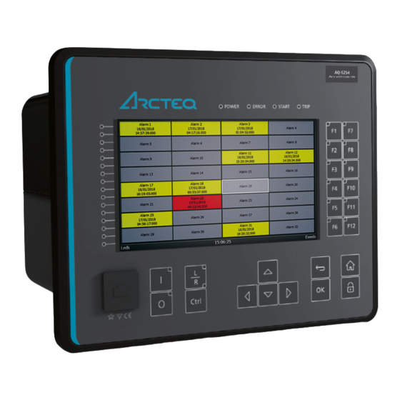
4.3 Alarming function Figure. 4.3 - 2. Front panel view Signal alarming is the main feature of AQ-S254 Alarming devices. The alarming unit has 128 alarms the user can set. The user defines each alarm description and activating signal. These settings are done in the Alarm settings menu ( Control →... - Page 19 If the alarm signal's ON state has been checked in the Event Mask , an ALARM ON event is recorded with a time stamp into the event history. These alarms are also reported in the communication protocol if one is in use. © Arcteq Relays Ltd IM00024...
- Page 20 Number of pages used. Pages can be scrolled with left and right arrow buttons. Each page Pages used as many columns and rows as is defined with following two parameters. Columns Number of columns used per page. Rows Number of rows used per page. © Arcteq Relays Ltd IM00024...
- Page 21 If alarm is cleared when signal is active, color will change to what has been set to Active cleared color in Carousel designer (orange by default). © Arcteq Relays Ltd IM00024...
- Page 22 If Zoom popup parameter is enabled in Carousel designer menu it is possible to enlarge alarms by pressing the up-arrow button. Once in zoomed mode direction arrows up, down, left and right can be used for choosing the alarm. Use Back-button to exit zoomed mode. © Arcteq Relays Ltd IM00024...
- Page 23 Alarms can be also cleared by using the CLEAR ALL ALARMS signal in the logic editor. In the example below, a physical push button activates Digital Input 1 which is connected to CLEAR ALL ALARMS. © Arcteq Relays Ltd IM00024...
- Page 24 → Logic ). Buzzer activation and deactivation AQ-S214 and AQ-S254 Alarming devices do not have an integrated buzzer. However, if an alarming buzzer is needed it is possible to connect an external buzzer. It is activated by one of the output relays of the device.
-
Page 25: Control Functions
Figure. 4.4.1 - 10. Simplified function block diagram of the setting group selection function. © Arcteq Relays Ltd IM00024... - Page 26 Table. 4.4.1 - 13. Settings of the setting group selection function. Name Range Default Description • SG1 • SG2 • SG3 Active setting • SG4 Displays which setting group is active. group • SG5 • SG6 • SG7 • SG8 © Arcteq Relays Ltd IM00024...
- Page 27 The selection of Setting group 5 ("SG5"). Has the fourth lowest priority input in setting group control. group Can be controlled with pulses or static signals. If static signal control is applied, SG6, SG7 and SG8 requests will not be processed. © Arcteq Relays Ltd IM00024...
- Page 28 Petersen coil is connected when the network is compensated, or whether it is open when the network is unearthed. Figure. 4.4.1 - 12. Setting group control – one-wire connection from Petersen coil status. © Arcteq Relays Ltd IM00024...
- Page 29 Setting group 2 is active. This way, if the wire is broken for some reason, the setting group is always controlled to SG2. Figure. 4.4.1 - 13. Setting group control – two-wire connection from Petersen coil status. © Arcteq Relays Ltd IM00024...
- Page 30 The application-controlled setting group change can also be applied entirely from the device's internal logics. For example, the setting group change can be based on the cold load pick-up function (see the image below). © Arcteq Relays Ltd IM00024...
- Page 31 ON, OFF, or both. The events triggered by the function are recorded with a time stamp. Table. 4.4.1 - 15. Event messages. Event block name Event names SG2...8 Enabled SG2...8 Disabled SG1...8 Request ON SG1...8 Request OFF Remote Change SG Request ON © Arcteq Relays Ltd IM00024...
-
Page 32: Object Control And Monitoring
The main outputs of the function are the OBJECT OPEN and OBJECT CLOSE control signals. Additionally, the function reports the monitored object's status and applied operations. The setting parameters are static inputs for the function, which can only be changed by the user in the function's setup phase. © Arcteq Relays Ltd IM00024... - Page 33 • On Set mode of OBJ block. • Blocked OBJ LN mode • Test This parameter is visible only when Allow setting of individual • Test/Blocked LN mode is enabled in General menu. • Off © Arcteq Relays Ltd IM00024...
- Page 34 • Not in use close the breaker (depending on "Ready High or Low" selection). Open Displays the number of successful "Open" requests. 0…2 –1 requests Close Displays the number of successful "Close" requests. 0…2 –1 requests © Arcteq Relays Ltd IM00024...
- Page 35 IN. "1" means that the withdrawable object In") cart is in. WD Object Out A link to a physical digital input. The monitored withdrawable ("Withdrw.CartOut.Status object's position is OUT. "1" means that the withdrawable In") object cart is pulled out. © Arcteq Relays Ltd IM00024...
- Page 36 Table. 4.4.2 - 20. Control settings (DI and Application). Signal Range Description • User Access level for MIMIC • Operator Defines what level of access is required for MIMIC control • Configurator control. The default is the "Configurator" level. • Super user © Arcteq Relays Ltd IM00024...
- Page 37 Blocking and interlocking can be based on any of the following: other object statuses, a software function or a digital input. The image below presents an example of an interlock application, where the closed earthing switch interlocks the circuit breaker close command. © Arcteq Relays Ltd IM00024...
- Page 38 The function uses the circuit breaker's manufacturer-supplied data for the breaker operating cycles in relation to the interrupted current magnitudes. © Arcteq Relays Ltd IM00024...
- Page 39 Condition monitoring parameters can be found from Control → Objects → Object X → APP CONTR → Condition Monitoring . Table. 4.4.2 - 22. Breaker supervision settings and status indications. Name Range Default Description • Disabled Condition monitoring Disabled Enabled the breaker condition monitoring function. • Enabled © Arcteq Relays Ltd IM00024...
- Page 40 Condition Alarm 2 Enable Disabled Enables Alarm 2. • Enabled Condition Alarm 2 when When the amount of operations left is less than value 0...200 000 operations less than set here, Alarm 2 will activate. © Arcteq Relays Ltd IM00024...
- Page 41 Close Command On OBJ1...OBJ10 Close Command Off OBJ1...OBJ10 Open Blocked On OBJ1...OBJ10 Open Blocked Off OBJ1...OBJ10 Close Blocked On OBJ1...OBJ10 Close Blocked Off OBJ1...OBJ10 Object Ready OBJ1...OBJ10 Object Not Ready OBJ1...OBJ10 Sync Ok OBJ1...OBJ10 Sync Not Ok © Arcteq Relays Ltd IM00024...
- Page 42 The cause of an "Open" command's failure. Close fail The cause of a "Close" command's failure. Open command The source of an "Open" command. Close command The source of an "Open" command. General status The general status of the function. © Arcteq Relays Ltd IM00024...
-
Page 43: Indicator Object Monitoring
Close input A link to a physical digital input. The monitored indicator's signal selected by the user ("Ind.X CLOSE status. "1" refers to the active "Close" state of the monitored Close indicator. (SWx) Status In") © Arcteq Relays Ltd IM00024... -
Page 44: Milliampere Output Control
3 and 4 Enable mA output channels 5 and 6 mA option • Disabled Enables and disables the outputs of the Disabled card 2 • Enabled mA output card 2. Enable mA output channels 7 and 8 © Arcteq Relays Ltd IM00024... - Page 45 The mA output value when the measured value mA output 0.0000…24.0000mA 0.0001mA 0mA is equal to or greater than Input value 2. value 2 Figure. 4.4.4 - 19. Example of the effects of mA output channel settings. © Arcteq Relays Ltd IM00024...
-
Page 46: Programmable Control Switch
(see the image below). The switch cannot be controlled by an auxiliary input, such as digital inputs or logic signals; it can only be controlled locally (mimic) or remotely (RTU). Settings. These settings can be accessed at Control → Device I/O → Programmable control switch . © Arcteq Relays Ltd IM00024... -
Page 47: User Buttons
LED at the top left corner of the button. The LED can be configured to activate red, orange or green color from button status or any other logical binary signal. General user button settings can be set at Control → Device IO → User-button Settings . © Arcteq Relays Ltd IM00024... -
Page 48: Analog Input Scaling Curves
Range Step Default Description Analog input • Disabled Disabled Enables and disables the input. scaling • Activated Scaling curve • Disabled Enables and disables the scaling curve and Disabled 1...10 • Activated the input measurement. © Arcteq Relays Ltd IM00024... - Page 49 Curve1...10 input 000.00...1 000 0.00001 0 is above the set limit, "ASC1...4 input out of maximum 000.00 range" is activated. -1 000 Curve1...10 output 000.00...1 000 0.00001 - Displays the output of the curve. 000.00 © Arcteq Relays Ltd IM00024...
- Page 50 Scales the measured milliampere signal at Point 2..10 Allows the user to create their own curve with up to twenty • Not used curvepoint (20) curve points, instead of using a linear curve between two • Used used 3...20 points. © Arcteq Relays Ltd IM00024...
-
Page 51: Logical Outputs
Table. 4.4.8 - 36. Logical output user description. Name Range Default Description User editable Logical 1...31 Description of the logical output. This description is used in description output characters several menu types for easier identification. LO1...64 1...64 © Arcteq Relays Ltd IM00024... -
Page 52: Logical Inputs
Figure. 4.4.9 - 21. Operation of logical input in "Hold" and "Pulse" modes. A logical input pulse can also be extended by connecting a DELAY-low gate to a logical output, as has been done in the example figure below. © Arcteq Relays Ltd IM00024... - Page 53 1...32 NOTICE! TICE! After editing user descriptions the event history will start to use the new description only after resetting the HMI. HMI can be reset from General → Device info → HMI restart . © Arcteq Relays Ltd IM00024...
- Page 54 The function's output signals can be used for direct I/O controlling and user logic programming. Table. 4.4.9 - 39. Event messages. Event block name Event names LOGIC2 Logical in 1...32 ON LOGIC2 Logical in 1...32 OFF © Arcteq Relays Ltd IM00024...
-
Page 55: Communica A Tion
Ethernet connection. Virtual Ethernet has its own separate IP address and network configurations. All Ethernet-based protocol servers listen for client connections on the IP addresses of both the physical Ethernet and the Virtual Ethernet. © Arcteq Relays Ltd IM00024... - Page 56 Bitrate used by serial fiber channels. • 38400bps Databits 7...8 Databits used by serial fiber channels. • None Parity • Even Paritybits used by serial fiber channels. • Odd Stopbits 1...2 Stopbits used by serial fiber channels. © Arcteq Relays Ltd IM00024...
-
Page 57: Time Synchronization
→ Synchronization → General . Table. 5.2 - 45. General time synchronization source settings. Name Range Description • Internal • External NTP Time synchronization source • External serial Selection of time synchronization source. • IRIG-B • PTP © Arcteq Relays Ltd IM00024... -
Page 58: Internal
Grandmaster clock. In the PTP network there can also be Boundary and Transparent clock roles, these are most often PTP enabled switches that can redistribute time or compensate for their delays. © Arcteq Relays Ltd IM00024... - Page 59 Clock class or frequency distributed by the Grandmaster PTP Instance Clock The expected accuracy of a PTP Instance when it is the Grandmaster PTP accuracy Instance, or in the event it becomes the Grandmaster PTP Instance © Arcteq Relays Ltd IM00024...
-
Page 60: Communication Protocols
AQ-25x frame units support both Edition 1 and 2 of IEC 61850. The following services are supported by IEC 61850 in Arcteq devices: • Up to six data sets (predefined data sets can be edited with the IEC 61850 tool in AQtivate) •... - Page 61 Reactive 0.1…1000.0 Determines the data reporting deadband 2 kVar energy deadband kVar kVar settings for this measurement. 0.1…1000.0 Determines the data reporting deadband Active power deadband 2 kW settings for this measurement. © Arcteq Relays Ltd IM00024...
-
Page 62: Logical Device Mode And Logical Node Mode
• LNBeh can be reported through Beh data object in all logical nodes. • LDMod is only visible through logical node zero's Mod data object (LLN0.Mod). Mode and behavior values There are 5 values defined for mode and behavior: On, Blocked, Test, Test / Blocked and Off. © Arcteq Relays Ltd IM00024... - Page 63 Table. 5.3.1.1 - 52. All possible logical device and logical node combinations. LDMod LNMod LNBeh Test / Blocked Test Blocked Test / Blocked Test / Blocked Test / Blocked Test Test / Blocked Blocked Test / Blocked Test / Blocked © Arcteq Relays Ltd IM00024...
- Page 64 Processed as Processed as Processed as Processed as Questionable questionable questionable questionable questionable processed q.test = False q.validity = Good Processed as Processed as Processed as Processed as invalid invalid valid valid processed q.test = True © Arcteq Relays Ltd IM00024...
- Page 65 “Processed as questionable” and “Processed as invalid” in the same way with “Not processed”. Only "Processed as valid" is passed to the application. Table. 5.3.1.1 - 54. Arcteq's implementation of processing of incoming data in different behaviors. Blocked...
-
Page 66: Goose
• Off 5.3.1.2 GOOSE Arcteq devices support both GOOSE publisher and GOOSE subscriber. GOOSE subscriber is enabled with the "GOOSE subscriber enable" parameter at Communication → Protocols → IEC 61850/ GOOSE. The GOOSE inputs are configured using either the local HMI or the AQtivate software. - Page 67 For other publishers, non-simulated frames are accepted normally (given no simulated frame is received from that publisher). This behavior ends when the setting is set back to No. GOOSE input settings The table below presents the different settings available for all 64 GOOSE inputs. © Arcteq Relays Ltd IM00024...
- Page 68 Table. 5.3.1.2 - 61. GOOSE input user description. Name Range Default Description User editable 1...31 GOOSE Description of the GOOSE input. This description is used in several description GI x characters IN x menu types for easier identification. © Arcteq Relays Ltd IM00024...
- Page 69 GOOSE signals generate events from status changes. The user can select which event messages are stored in the main event buffer: ON, OFF, or both. The events triggered by the function are recorded with a time stamp and with process data values. The time stamp resolution is 1 ms. © Arcteq Relays Ltd IM00024...
-
Page 70: Modbus/Tcp And Modbus/Rtu
1. Some masters might begin numbering holding register from 0 instead of 1; this will cause an offset of 1 between the device and the master. Modbus map can be edited with Modbus Configurator ( Tools → Communication → Modbus Configurator ). © Arcteq Relays Ltd IM00024... -
Page 71: Iec 103
TE: Once the configuration file has been loaded, the IEC 103 map of the device can be found in the AQtivate software ( Tools → IEC 103 map ). The following table presents the setting parameters for the IEC 103 protocol. © Arcteq Relays Ltd IM00024... -
Page 72: Iec 101/104
Table. 5.3.4 - 67. IEC 104 settings. Name Range Step Default Description IEC 104 • Disabled Disabled Enables and disables the IEC 104 communication protocol. enable • Enabled IP port 0…65 535 2404 Defines the IP port used by the protocol. © Arcteq Relays Ltd IM00024... - Page 73 • 1/10 000 Power factor • 1/100 000 • 1/1 000 000 Frequency • 10 • 100 • 1000 Current • 10 000 • 100 000 Residual current • 1 000 000 Voltage Residual voltage Angle © Arcteq Relays Ltd IM00024...
-
Page 74: Spa
The full SPA signal map can be found in AQtivate ( Tools → SPA map ). The SPA event addresses can be found at Tools → Events and logs → Event list . © Arcteq Relays Ltd IM00024... -
Page 75: Dnp3
Defines the length of the time-out for the link layer. time-out 000ms Link layer 1…20 Defines the number of retries for the link layer. retries Diagnostic Counts the total number of errors in received and sent - Error 0…2 messages. counter © Arcteq Relays Ltd IM00024... - Page 76 • Var 5 • Var 1 • Var 2 • Var 3 Group 32 variation (AI change) Var 5 Selects the variation of the analog signal change. • Var 4 • Var 5 • Var 7 © Arcteq Relays Ltd IM00024...
-
Page 77: Modbus I/O
Range Description I/O module Defines the Modbus unit address for the selected I/O Module (A, B, or C). If 0…247 X address this setting is set to "0", the selected module is not in use. © Arcteq Relays Ltd IM00024... -
Page 78: Analog Fault Registers
FLX (Fault locator) Select • TRIP signal Selects what triggers the fault register recording: TRIP record • START signal the selected function's TRIP signal, its START signal trigger • START and TRIP signals signal, or either one. © Arcteq Relays Ltd IM00024... -
Page 79: Modbus Gateway
Arc protection relays AQ-103 and AQ-103 LV Modbus variant is designed to work as a sub unit with Modbus Gateway master. More details about AQ-103 and AQ-103 LV capabilities and how to set them up can be found in AQ-103 Instruction manual (arcteq.fi./downloads/). Also see application example at the end of this chapter. - Page 80 Meas x Describe bit 1...31 Acq. Bit User settable description for the signal. This description is used in signal x characters several menu types for easier identification. Describe doube Acq. bit signal x Binary x © Arcteq Relays Ltd IM00024...
- Page 81 RTU. AQ-103 Modbus variant is able to report various signals like number of installed sensors, sensor activations, I/O activations etc. Holding registers of each signal can be found in the AQ-103 instruction manual. © Arcteq Relays Ltd IM00024...
- Page 82 Figure. 5.5 - 25. To report imported bit signals to SCADA the signals must be connected to a logical output. © Arcteq Relays Ltd IM00024...
- Page 83 Figure. 5.5 - 26. Example mimic where sensor activation location is indicated with a symbol. Figure. 5.5 - 27. In AQ-S254 it is possible to set up the display to show sensor activations in alarm display. © Arcteq Relays Ltd...
-
Page 84: Connections Of Aq-S254
A A Q Q -S254 -S254 6 Connections and application examples Instruction manual Version: 2.11 6 Connections and application examples 6.1 Connections of AQ-S254 Figure. 6.1 - 28. AQ-S254 variant without add-on modules. © Arcteq Relays Ltd IM00024... - Page 85 A A Q Q -S254 -S254 6 Connections and application examples Instruction manual Version: 2.11 Figure. 6.1 - 29. AQ-S254 variant with digital input and output modules. © Arcteq Relays Ltd IM00024...
- Page 86 A A Q Q -S254 -S254 6 Connections and application examples Instruction manual Version: 2.11 Figure. 6.1 - 30. AQ-S254 application example. © Arcteq Relays Ltd IM00024...
-
Page 87: Construction And Installation Tion
CPU, a number of inputs and outputs, and the power supply). The images below present the modules of both the non-optioned model (AQ- X254-XXXXXXX-AAAAAAAAAAAAAA AAAAAAAAAAAAAA) and the almost fully optioned model (AQ- X254-XXXXXXX-BBBBBBBBBBBCA BBBBBBBBBBBCAJ J ). Figure. 7.1 - 31. Modular construction of AQ-X254-XXXXXXX-AAAAAAAAAAAAAA © Arcteq Relays Ltd IM00024... - Page 88 In field upgrades, therefore, add-on modules must be ordered from Arcteq Relays Ltd. or its representative who can then provide the module with its corresponding unlocking code to allow the device to operate correctly once the hardware configuration has been upgraded.
- Page 89 Communication port 3 or higher, as Communication ports 1 and 2 already exist in the CPU module (which is scanned, and thus designated, first). After a communication port is detected, it is added into the device's communication space and its corresponding settings are enabled. © Arcteq Relays Ltd IM00024...
-
Page 90: Cpu Module
Digital input 3, nominal threshold voltage 24 V, 110 V or 220 V. X1-4 Common GND for digital inputs 1, 2 and 3. X1-5:6 Output relay 1, with a normally open (NO) contact. X1-7:8 Output relay 2, with a normally open (NO) contact. © Arcteq Relays Ltd IM00024... - Page 91 Defines the delay for the status change from 1 to 0. off time DIx AC • Disabled Selects whether or not a 30-ms deactivation delay is Disabled mode • Enabled added to account for alternating current. © Arcteq Relays Ltd IM00024...
- Page 92 (T1…Tx), it takes an additional 5 ms round. Therefore, when a digital input controls a digital output internally, it takes 0…15 milliseconds in theory and 2…13 milliseconds in practice. NOTICE! TICE! The mechanical delay of the relay is no not t included in these approximations! © Arcteq Relays Ltd IM00024...
-
Page 93: Option Cards
1 V. All digital inputs are scannced in 5 ms program cycles, and their pick-up and release delays as well as their NO/NC selection can be set with software. © Arcteq Relays Ltd IM00024... - Page 94 (NC) defines whether or not the digital input is considered activated when the digital input channel is energized. The diagram below depicts the digital input states when the input channels are energized and de- energized. © Arcteq Relays Ltd IM00024...
- Page 95 Control → Device IO → Digital inputs → Digital input voltages . Table. 7.3.1 - 85. Digital input channel voltage measurement. Name Range Step Description DIx Voltage now 0.000...275.000 V 0.001 V Voltage measurement of a digital input channel. © Arcteq Relays Ltd IM00024...
-
Page 96: Digital Output Module (Optional)
For technical details please refer to the chapter titled "Digital output module" in the "Technical data" section of this document. Digital output descriptions Option card outputs can be given a description. The user defined description are displayed in most of the menus: • logic editor © Arcteq Relays Ltd IM00024... -
Page 97: Rtd Input Module (Optional)
After editing user descriptions the event history will start to use the new description only after resetting the HMI. HMI can be reset from General → Device info → HMI restart . 7.3.3 RTD input module (optional) Figure. 7.3.3 - 38. RTD input module connectors. © Arcteq Relays Ltd IM00024... -
Page 98: Serial Rs-232 Communication Module (Optional)
2-wire, 3-wire and 4-wire RTD sensors. The sensor type can be selected with software for two groups, four channels each. The card supports Pt100 and Pt1000 sensors Figure. 7.3.3 - 39. RTD sensor connection types. 7.3.4 Serial RS-232 communication module (optional) Figure. 7.3.4 - 40. Serial RS-232 module connectors. © Arcteq Relays Ltd IM00024... - Page 99 COM F – Clock sync GND Clock synchronization input Pin 12 The option card includes two serial communication interfaces: COM E is a serial fiber interface with glass/plastic option, COM F is an RS-232 interface. © Arcteq Relays Ltd IM00024...
-
Page 100: Lc Or Rj45 100 Mbps Ethernet Communication Module (Optional)
• Communication port D, 100 Mbps LC fiber connector. • RJ-45 connectors COM D: • 62.5/125 μm or 50/125 μm multimode (glass). • 10BASE-T and 100BASE-TX • Wavelength 1300 nm. Both cards support both HSR and PRP protocols. © Arcteq Relays Ltd IM00024... -
Page 101: Double St 100 Mbps Ethernet Communication Module (Optional)
For other redundancy options, please refer to the option card "LC 100 Mbps Ethernet communication module". The images below present two example configurations: the first displays a ring configuration (note how the third party devices are connected in a separate ring), while the second displays a multidrop configuration. © Arcteq Relays Ltd IM00024... - Page 102 A A Q Q -S254 -S254 7 Construction and installation Instruction manual Version: 2.11 Figure. 7.3.6 - 43. Example of a ring configuration. Figure. 7.3.6 - 44. Example of a multidrop configuration. © Arcteq Relays Ltd IM00024...
-
Page 103: Double Rj45 10/100 Mbps Ethernet Communication Module (Optional)
• Two Ethernet ports RJ-45 connectors • RJ-45 connectors • 10BASE-T and 100BASE-TX This option card supports multidrop configurations. For other redundancy options, please refer to the option card "LC 100 Mbps Ethernet communication module". © Arcteq Relays Ltd IM00024... -
Page 104: Dimensions And Installation
(½) of the rack's width, meaning that a total of two devices can be installed to the same rack next to one another. The figures below describe the device dimensions (first figure), the device installation (second), and the panel cutout dimensions and device spacing (third). Figure. 7.4 - 47. Device dimensions. © Arcteq Relays Ltd IM00024... - Page 105 A A Q Q -S254 -S254 7 Construction and installation Instruction manual Version: 2.11 Figure. 7.4 - 48. Device installation. © Arcteq Relays Ltd IM00024...
- Page 106 A A Q Q -S254 -S254 7 Construction and installation Instruction manual Version: 2.11 Figure. 7.4 - 49. Panel cut-out and spacing of the devices. © Arcteq Relays Ltd IM00024...
-
Page 107: Technic Echnical Da Al Data Ta
< 20 W (no option cards) Power consumption < 40 W (maximum number of option cards) Maximum permitted interrupt time < 40 ms with 110 VDC DC ripple < 15 % Other Minimum recommended fuse rating MCB C2 © Arcteq Relays Ltd IM00024... -
Page 108: Cpu Communication Ports
Port media Copper Ethernet RJ-45 Number of ports Features IEC 61850 IEC 104 Modbus/TCP Port protocols DNP3 Telnet Data transfer rate 100 MB/s System integration Can be used for system protocols and for local programming © Arcteq Relays Ltd IM00024... -
Page 109: Cpu Digital Inputs
8.1.1.4 CPU digital outputs Table. 8.1.1.4 - 94. Digital outputs (Normally Open) Rated values Rated auxiliary voltage 265 V (AC/DC) Continuous carry Make and carry 0.5 s 30 A Make and carry 3 s 15 A © Arcteq Relays Ltd IM00024... -
Page 110: Option Cards
5…265 V (AC/DC) Current drain 2 mA Scanning rate 5 ms Activation/release delay 5...11 ms Settings Pick-up threshold Software settable: 16…200 V, setting step 1 V Release threshold Software settable: 10…200 V, setting step 1 V © Arcteq Relays Ltd IM00024... -
Page 111: Digital Output Module
Software settable: Normally On/Normally Off Terminal block connection Screw connection terminal block (standard) Phoenix Contact MSTB 2,5/10-ST-5,08 Spring cage terminals block (option) Phoenix Contact FKC 2,5/10-STF-5,08 Solid or stranded wire Nominal cross section 2.5 mm © Arcteq Relays Ltd IM00024... -
Page 112: Rtd Input Module
Serial fiber (GG/PP/GP/PG) Serial port wavelength 660 nm Cable type 1 mm plastic fiber Terminal block connections Spring cage terminals block Phoenix Contact DFMC 1,5/ 6-STF-3,5 Solid or stranded wire Nominal cross section 1.5 mm © Arcteq Relays Ltd IM00024... -
Page 113: Double Lc 100 Mbps Ethernet Communication Module
Transmitter wavelength 1260…1360 nm (nominal: 1310 nm) Receiver wavelength 1100…1600 nm Maximum distance 2 km IRIG-B Connector Screw connection terminal block Phoenix Contact MC 1,5/ 2-ST-3,5 BD:1-2 Solid or stranded wire Nominal cross section 1.5 mm © Arcteq Relays Ltd IM00024... -
Page 114: Display
Force change overrule of local controls either from the setting tool, HMI or SCADA Operation time Reaction time <5 ms from receiving the control signal 8.2.1.2 Object control and monitoring Table. 8.2.1.2 - 104. Technical data for the object control and monitoring function. General Number of objects © Arcteq Relays Ltd IM00024... -
Page 115: Indicator Object Monitoring
±0.2 % of the measured current, rest 0.5 % - Operation counter ±0.5 % of operations deducted 8.2.1.3 Indicator object monitoring Table. 8.2.1.3 - 106. Technical data for the indicator object monitoring function. General Number of objects © Arcteq Relays Ltd IM00024... -
Page 116: Monitoring Functions
General information Event history capacity 15 000 events Event timestamp resolution 1 ms 8.3 Tests and environmental Electrical environment compatibility Table. 8.3 - 109. Disturbance tests. All tests CE-approved and tested according to EN 60255-26 Emissions © Arcteq Relays Ltd IM00024... - Page 117 Table. 8.3 - 112. Environmental tests. Damp heat (cyclic) EN 60255-1, IEC 60068-2-30 Operational: +25…+55 °C, 93…97 % (RH), 12+12h Dry heat Storage: +70 °C, 16 h EN 60255-1, IEC 60068-2-2 Operational: +55 °C, 16 h © Arcteq Relays Ltd IM00024...
- Page 118 Height: 208 mm Dimensions Width: 257 mm (½ rack) Depth: 165 mm (no cards or connectors) Weight 1.5 kg With packaging (gross) Height: 250 mm Dimensions Width: 343 mm Depth: 256 mm Weight 2.0 kg © Arcteq Relays Ltd IM00024...
-
Page 119: Ordering Inf Dering Informa Ormation Tion
External 8-ch Thermocouple mA Input module, pre- Requires an external 24 VDC AX008 configured supply. AX013 AQ-250 series raising frame 120mm AQX014 AQ-250 series raising frame 40mm AQX015 AQ-250 series wall mounting bracket © Arcteq Relays Ltd IM00024... -
Page 120: Contact And R Ence Informa Ormation Tion
Arcteq Relays Ltd. Visiting and postal address Kvartsikatu 2 A 1 65300 Vaasa, Finland Contacts Phone: +358 10 3221 370 Website: arcteq.com Technical support: arcteq.com/support-login +358 10 3221 388 (EET 9:00 – 17.00) E-mail (sales): sales@arcteq.fi © Arcteq Relays Ltd IM00024...
Need help?
Do you have a question about the AQ-S254 and is the answer not in the manual?
Questions and answers