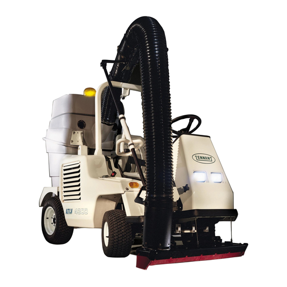
Tennant ATLV 4300 Instruction Bulletin
Hide thumbs
Also See for ATLV 4300:
- Service manual (206 pages) ,
- Operator's manual (102 pages) ,
- Instruction bulletin (17 pages)
Advertisement
INSTRUCTION BULLETIN
NOTE: DO NOT DISCARD the Parts List from the Instruction Bulletin. Place the Parts
List in the appropriate place in your machine manual for future reference.
Retaining the Parts List will make it easier to reorder individual parts and will
save you the cost of ordering an entire kit.
NOTE: Numbers in parenthesis ( ) are reference numbers for parts listed in Bill of Materials.
Installation instructions for kit number 368672
DESCRIPTION:
This kit contains the parts needed to install a hopper cover support kit on the model ATLV
4300 Litter Vacuum.
Please follow step-by-step instructions.
SPECIAL TOOLS / CONSIDERATIONS: Hand drill, 3/8 drill bit.
(Estimated time to complete: 1 hour)
PREPARATION:
(Refer to FIG. 1 and 2)
1. Turn the machine power on. See the STARTING THE
MACHINE section of the manual.
FOR SAFETY: Before leaving or servicing
machine, stop on level surface and set parking
brake. Then turn off machine and remove key.
INSTALLATION:
(Refer to FIG. 1 and 2)
1. Locate the hopper cover hinge on the right hand
side of the machine.
2. Remove the two outside bolts and washers securing
the hinge to the hopper on the right hand side of the
machine. Mount the angle (1) to the outside of the
right side hinge using the hinge mounting hardware.
IB 340549 (5-02)
No. 340549
Machine: ATLV 4300
Published: 5-02
Rev. 00
1
1
Advertisement
Table of Contents

Subscribe to Our Youtube Channel
Summary of Contents for Tennant ATLV 4300
- Page 1 No. 340549 Machine: ATLV 4300 INSTRUCTION BULLETIN Published: 5-02 Rev. 00 NOTE: DO NOT DISCARD the Parts List from the Instruction Bulletin. Place the Parts List in the appropriate place in your machine manual for future reference. Retaining the Parts List will make it easier to reorder individual parts and will save you the cost of ordering an entire kit.
- Page 2 3. Using the dimensions shown in figure 2, and the smaller angle (2) as a template, mark and drill two 3/8 mounting holes in the right side hinge mounting bracket. (Refer to FIG 1 and 2). 4. Mount the smaller angle (2) to the hinge mounting bracket with two M08 hex screws (5), washers (3) and M08 lock nuts (6).
- Page 3 5. Install the eye bolt (8) in the hole in the top of the smaller angle (2). Secure the eye bolt (8) in place with two lock nuts (6). (Refer to FIG 2) 6. Connect one end of the tension spring (7) to the large angle (1) mounted against the right hinge.
- Page 4 368662 angle 50864 spring 32536 eye bolt 368663 angle 32983 nut (2) 60mm (2.375) 09011 screw (2) 25mm (1.0) 08709 nut (2) 44mm (1.750) 60mm (2.375) 165mm (6.5) Rework bracket 367351 ∅0.375 (2) FIG. 2 - - Hopper Support Installation IB 340549 (5-02)
- Page 5 Nut, hex, lock, M08 X 1.25, NL 09011 Screw, hex, M08 X 1.25 X 30, Ss 32983 Nut, hex, lock, 0.31--18, NL 50864 Spring, tension 32536 Bolt, eye, TENNANT COMPANY P. O. Box 1452 Minneapolis, MN 55440-1452 IB 340549 (5-02)


Need help?
Do you have a question about the ATLV 4300 and is the answer not in the manual?
Questions and answers