
Related Manuals for Tennant S12


Summary of Contents for Tennant S12
- Page 1 (Electric) Sweeper English EN Operator Manual 331361 Rev. 01 (06-2007) *331361* www.tennantco.com Home Find... Go To..
- Page 2 Specifications and parts are subject to change without notice. Copyright E 2005, 2007 TENNANT Company, Printed in The Netherlands DECLARATION OF CONFORMITY FOR MACHINERY (according to Annex II A of the Machinery Directive) Herewith declares, on our own responsibility, that the machinery TENNANT N.V.
-
Page 3: Table Of Contents
......TRANSPORTING THE MACHINE ..S12 331361 (9- -05) Home Find... Go To.. -
Page 4: Safety Precautions
- - Avoid contact with battery acid. WARNING: Batteries emit hydrogen gas. - - Use Tennant supplied or equivalent Explosion or fire can result. Keep replacement parts. sparks and open flame away. Keep covers open when charging. - Page 5 FOR SAFETY LABEL - - LOCATED ON THE BATTERY CHARGING LABEL - - LOCATED SIDE OF THE OPERATOR COMPARTMENT. IN THE BATTERY COMPARTMENT. FLYING DEBRIS LABEL - - LOCATED ABOVE THE DRIVE AXLE. S12 331361 (9- -05) Home Find... Go To..
-
Page 6: Operation
- Check the machine for shipping damage. Check to make sure the machine is complete per shipping instructions. - After operation, follow the recommended daily and hourly procedures stated in the MAINTENANCE CHART. S12 331361 (9- -05) Home Find... Go To.. -
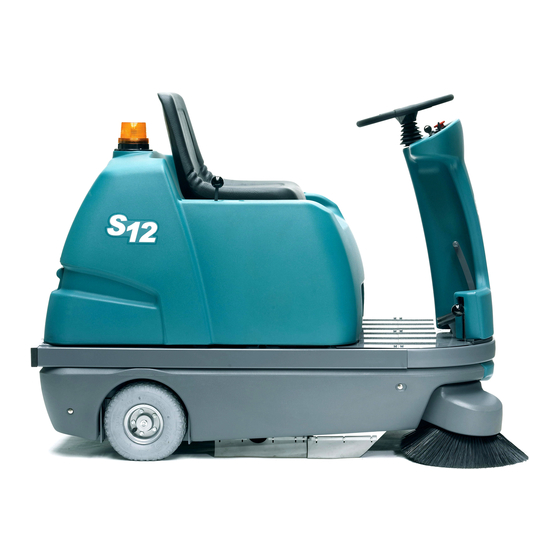
Page 7: Machine Components
P. Drive wheel G. Horn push button Q. Side cover H. Key switch R. Front trim panel I. Steering wheel S. Pivotable side brushes J. Front console T. Front wheel with drum brake S12 331361 (9- -05) Home Find... Go To.. -
Page 8: Safety Devices
3. Install the batteries. 4. Connect the batteries. Refer to technical data circuit diagram. 5. Replace the main cover. 6. Install the side brush (See: Installing the Side Brushes). S12 331361 (9- -05) Home Find... Go To.. -
Page 9: Operation
NOTE: A red LED starts flashing on the battery condition display indicating that the machine is ready for operation. After a few seconds the LED‘s will change to indicate the battery’s charging condition. S12 331361 (9- -05) Home Find... Go To.. -
Page 10: Sweeping
The side brush(es) begins to rotate. 5. Press and hold the switch in the filter cleaner position for about 5--10 seconds. 3. Lower the side brush with the side brush lever. S12 331361 (9- -05) Home Find... Go To.. -
Page 11: Turning Off The Sweeper
1. Position the debris hopper in front of the sweeper opening. 2. Align the debris hopper front guides level with guide rails. 3. Slide the debris hopper into the sweeper. 4. Turn the locking device downward. S12 331361 (9- -05) Home Find... Go To.. -
Page 12: Replacing The Filter
-circuits. Do not use high- -pressure cleaning devices. A. Filter seal Make sure the filter is facing the right direction when installing. The seal filter must show towards the filter housing as shown. S12 331361 (9- -05) Home Find... Go To.. -
Page 13: Side Brushes
3. Slide the shim over the shaft of the side brush motor. 8. Reinstall the front panel. 4. Fasten the side brush to the shaft of the side brush motor with the fastening screw. S12 331361 (9- -05) Home Find... Go To.. -
Page 14: Main Brush
6. Pull the main brush out of the machine and remove any debris, strings, etc., from the 6. Reinstall the left side cover. brush compartment, the brush, the drive pin (see photo on the right) and the pick--up pin. S12 331361 (9- -05) Home Find... Go To.. -
Page 15: Setting The Main Brush Pattern
Course adjustments can be made with the cam adjuster. Loosen the knob to make an adjustment. Tighten the knob when finished with the adjustment. A. Forked lever adjuster B. Quick- -release clip C. Cam adjuster S12 331361 (9- -05) Home Find... Go To.. -
Page 16: Batteries
FOR SAFETY: Before leaving or servicing machine, stop on level surface, set parking brake, turn off machine, and remove key. FOR SAFETY: When maintaining or servicing machine, avoid contact with battery acid. S12 331361 (9- -05) Home Find... Go To.. -
Page 17: Brake
5. Fasten the brake cable lock. 1. Hold the adjustment nut of the cable in place with a wrench. 6. Repeat the brake check. 2. Loosen the back nut of the adjustment nut. S12 331361 (9- -05) Home Find... Go To.. -
Page 18: Circuit Breakers
FOR SAFETY: make sure to use straps that Grease the chain sprockets at regular intervals. withstand an increased load due to vibrations See maintenance chart. of the machine during transport. A. Front strap B. Rear strap S12 331361 (9- -05) Home Find... Go To.. -
Page 19: Maintenance Chart
-- Conduct trial run to check all operating elements. -- Check if brush drive chain is stretched or loosened. -- Check all bearings for wear. -- Check if seals are damaged or dislocated. S12 331361 (9- -05) Home Find... Go To.. -
Page 20: Machine Troubleshooting
Check fan and remove any Does not remain set obstruction Circuit breaker of propelling Drive wheels obstructed Jack up the sweeper check drive does not remain set differential operation of wheels and free running S12 331361 (9- -05) Home Find... Go To.. -
Page 21: Specifications
70 dB (A) ELECTRICAL INSTALLATION Circuit Circuit Measure Breakers Vacuum/filter cleaner Mainbrush 25 A Sidebrush(es) 10 A (20 A) Horn,busser, beacon Propel--system 45 A Battery--monitor, relais 20 A Fuse Controller Power Supply S12 331361 (9- -05) Home Find... Go To.. - Page 22 S12 331361 (9- -05) Home Find... Go To..
Need help?
Do you have a question about the S12 and is the answer not in the manual?
Questions and answers