Tennant ATLV 4300 Operator's Manual
Litter vacuum
Hide thumbs
Also See for ATLV 4300:
- Service manual (206 pages) ,
- Instruction bulletin (17 pages) ,
- Instruction bulletin (2 pages)
Table of Contents
Advertisement
Quick Links
Download this manual
See also:
Service Manual
Advertisement
Table of Contents

Subscribe to Our Youtube Channel
Related Manuals for Tennant ATLV 4300


Summary of Contents for Tennant ATLV 4300
- Page 1 ATLV 4300 Litter Vacuum Operator Manual TennantTrueR Parts North America / International 330510 For latest parts manual or other Rev. 17 (10-2014) language oprator manual, visit: *330510* www.tennantco.com/manuals...
- Page 2 ATLV is a United States trademarks of Tennant Company. Specifications and parts are subject to change without notice. Original Instructions, copyright E 1998−2003, 2005, 2007 − 2010, 2012, 2014 TENNANT Company, Printed in U.S.A.
-
Page 3: Table Of Contents
......VACUUM HEAD SKIRTS (OPTION) STOP VACUUMING ....ATLV 4300 330510 (4−09) - Page 4 ....INDEX ........ATLV 4300 330510 (1−10)
-
Page 5: Safety Precautions
− In areas with possible falling objects − Use cardboard to locate leaking unless equipped with overhead guard. hydraulic fluid under pressure. − Use TENNANT supplied or approved replacement parts. ATLV 4300 330510 (4−2012) - Page 6 380 mm (15 in) or less from the ground. − Set parking brake after machine is loaded. − Block machine tires. − Tie machine down to truck or trailer. ATLV 4300 330510 (6−02)
- Page 7 On The Rear Canister. FAN WARNING LABEL − FOR SAFETY LABEL − Located In The Engine Located Below The Operator Seat. Compartment. NOISE WARNING LABEL − Located EMISSIONS LABEL − Located Below The Operator’s Seat. Below The Operator’s Seat. ATLV 4300 330510 (8−98)
-
Page 8: Operation
- The model ATLVt 4300 has a GVWR of 1180 kg ( 2600 lbs.) Operate only on surfaces capable of supporting this weight. - After the first 50 hours of operation, follow the recommended procedures stated in the MAINTENANCE CHART. ATLV 4300 330510 (8−98) -
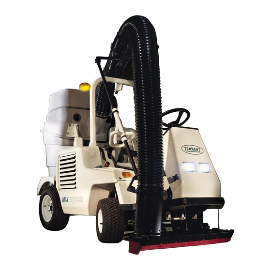
Page 9: Machine Components
Vacuum Hose Support Arm Vacuum Fan Hopper Roll Over Protection System Seat Belt Operator Seat Engine Vacuum Head (Option) Vacuum Adjustment Knob (Option) Vacuum Hose Rear View Mirrors Vacuum Wand Handle M. Vacuum Hose Support Arm Adjustment Knob ATLV 4300 330510 (8−98) -
Page 10: Control Panel Symbols
Circuit breaker #4 Glow Plug (Preheat) Circuit breaker #5 Hazard Light (Option) Circuit breaker #6 Signal Light (Option) Circuit breaker 7 Vacuum Head Control (Option) Circuit breaker 8 Vacuum Hose Height Adjustment Horn Water Dust Control (Option) ATLV 4300 330510 (12−01) -
Page 11: Controls And Instruments
Vacuum Head Switch (Option) Fuel Level Gauge Hourmeter Engine Temperature Light Engine Oil Pressure Light Charging System Light Thermo Sentryt Warning Light (Option) M. Vacant (No Reading) Hydraulic Filter Bypass Light Parking Brake Light (Option) Glow Plug Light ATLV 4300 330510 (9−00) - Page 12 OPERATION Horn Button Throttle Lever Work Lights Switch (Option) Operating/Hazard Lights Switch (Option) Operating Lights Switch Water Dust Control Switch (Option) Directional Pedal Brake Pedals Parking Brake Pedals Circuit Breaker Panel Windshield Wiper Knob (Option) ATLV 4300 330510 (12−01)
-
Page 13: Operation Of Controls
5 to 30 seconds depending on the weather conditions, the engine is ready to start. Start: Turn the key all the way clockwise. Release the key as soon as the engine starts. Stop: Turn the key counter-clockwise. ATLV 4300 330510 (8−98) -
Page 14: Turn Signal Lever (Option)
VACUUM HEAD SWITCH (OPTION) The vacuum head switch raises and lowers the vacuum head that mounts under the front end of the machine. Raise: Press the bottom of the switch. Lower: Press the top of the switch ATLV 4300 330510 (8−98) -
Page 15: Fuel Level Gauge
The engine temperature light comes on when the temperature of the engine coolant is more than 113 C (235 F). If the light comes on, stop operating the machine. Locate the problem and have it corrected. See the MAINTENANCE section of this manual. ATLV 4300 330510 (9−99) -
Page 16: Engine Oil Pressure Light
The Thermo Sentry will also shut off the vacuum fan. If this happens, stop the machine and eliminate the source of heat. Allow the sensor to cool, and it will reset automatically. ATLV 4300 330510 (8−98) -
Page 17: Hydraulic Filter Bypass Light
GLOW PLUG LIGHT The glow plug light comes on when the ignition switch is turned counterclockwise to the Glow Plug position. The light will go out when the engine is ready to start. ATLV 4300 330510 (9−00) -
Page 18: Operating Lights Switch
On: Press the switch to the forward position. The switch will light up. Off: Press the switch to the back position. The light in the switch will turn off. ATLV 4300 330510 (12−01) -
Page 19: Horn Button
Connect seat belt: Insert the male end of the seat belt into the female end until they click securely into place. Disconnect seat belt: Press the button on the female end buckle and pull the ends apart. ATLV 4300 330510 (12−01) -
Page 20: Fuses
15 A Horn CB−3 15 A Work Lights CB-4 15 A Operating Lights CB-5 15 A Brake/ Turn signals Back Up alarm CB-6 15 A Open Cab Acc. CB-7 15 A Options CB-8 15 A Options ATLV 4300 330510 (9−99) -
Page 21: Brake Pedals
The parking brake light (option) will turn on while the parking brake is set. Always set both parking brake pedals when parking the machine. Release parking brakes: Press on the brake pedals to unlock the parking brake pedals. ATLV 4300 330510 (8−98) -
Page 22: Directional Pedal
Neutral position. Note: There is a pedal angle adjustment pin behind the propelling pedal. Remove the pin, set the pedal at the desired angle for operation and reinsert the pin. ATLV 4300 330510 (9−99) -
Page 23: Operator Seat
Turn the knob counterclockwise to increase the angle of the backrest. The front−to−rear position lever adjusts the seat position. Adjust: Pull the lever out, slide the seat backward or forward to the desired position and release the lever. ATLV 4300 330510 (8−98) -
Page 24: Vacuum Wand Handle
To remove the vacuum hose from the optional vacuum head: Push forward and up on the vacuum wand handle, and lift the vacuum hose off the vacuum head. ATLV 4300 330510 (8−98) -
Page 25: Vacuum Hose Support Arm
Raise vacuum hose: Turn knob counter clockwise. Lower vacuum hose: Turn knob clockwise. Note: After turning the adjustment knob, pull the vacuum wand support arm down and let it spring up to determine the effect of the adjustment. Adjust further if necessary. ATLV 4300 330510 (8−28) -
Page 26: Vacuum Head Adjustment Knob (Option)
The bracket will “snap” and release the hopper when it is pushed down into the debris removal position. FOR SAFETY: When Using Machine, Do Not Move Machine With Hopper Open. ATLV 4300 330510 (8−98) -
Page 27: Latches
Open: Pull the rear of the latch away form the filter housing, and then unhooking the front of the latch from the keeper. Close: Hook the front of the latch onto the keeper and push latch towards the filter housing until it snaps into place. ATLV 4300 330510 (3−01) -
Page 28: How The Machine Works
4572 mm (15ft.) extension. When vacuuming is finished, check the vacuum hose, clean the hopper fan screen and empty the hopper. PRE-OPERATION CHECKLIST - Check under the machine for leaks (fuel, oil, coolant). ATLV 4300 330510 (4−09) - Page 29 OPERATION - Empty the engine air filter dust cap. - Check the engine oil level. - Check the fuel level. - Check the brakes and steering for proper operation. ATLV 4300 330510 (4−09)
- Page 30 - Check the coolant level in the overflow reservoir. - Check the radiator inlet screen for debris, and clean if required. - Check the vacuum bag for debris, and empty if required. - Check the water dust control tank, fill if required. (Option) ATLV 4300 330510 (4−09)
- Page 31 OPERATION - Check the vacuum fan screen for debris, and gently clean with a broom if required. - Check the hopper, empty if required. - Check the vacuum hose for damage, cracks and lodged debris. ATLV 4300 330510 (3−99)
- Page 32 OPERATION - Check the vacuum hose support arm for proper adjustment. - Check the vacuum wand handle for proper adjustment. - Check the vacuum head skirts for wear. (Option) ATLV 4300 330510 (8−98)
-
Page 33: Starting The Machine
1. Check the directional pedal to make sure it is in the middle neutral position. 2. Sit in the operator’s seat with your foot on the brake pedal or with the parking brake set. 3. Put on the seat belt. ATLV 4300 330510 (9−99) - Page 34 7. Allow the engine and hydraulic system to warm up three to five minutes. WARNING: Engine Emits Toxic Gases. Severe Respiratory Damage Or Asphyxiation Can Result. Provide Adequate Ventilation. Consult With Your Regulatory Agency For Exposure Limits. Keep Engine Properly Tuned. ATLV 4300 330510 (12−01)
- Page 35 OPERATION 8. Vacuum head option: Place the vacuum hose on to the vacuum head opening. 9. Step on the brake pedals firmly to release the parking brake. ATLV 4300 330510 (9−99)
- Page 36 11. Push the throttle lever forward to the middle operating position. 12. Step on the directional pedal and drive the machine to the area to be vacuumed. ATLV 4300 330510 (12−01)
-
Page 37: Vacuuming And Hose Information
For best results, maneuver the vacuum hose as close to debris as possible. Air flow picks up the debris, the vacuum doesn’t. Hold the hose end a few inches off the ground to allow air to enter the hose when picking up debris. ATLV 4300 330510 (8−98) - Page 38 WARNING: Spinning fan. Stop engine before opening debris canister. The rotating fan in the top of the debris cannister can become clogged with light debris. Clean with a broom when emptying bags. ATLV 4300 330510 (3−01)
-
Page 39: Operation On Inclines
Do not try to stabilize the machine by placing a foot on the ground. Do not drive the machine with the hopper open. FOR SAFETY: When Using Machine, Do Not Move Machine With Hopper Open. ATLV 4300 330510 (9−99) -
Page 40: Operation Over Curbs
Driving over any curb requires extra caution. Do not try to stabilize the machine by placing a foot on the ground when climbing over curbs. ATLV 4300 330510 (8−98) -
Page 41: Vacuuming
Adequate Ventilation. Consult With Your Regulatory Agency For Exposure Limits. Keep Engine Properly Tuned. 2. Take a firm hold of the vacuum wand handle. 3. Vacuum head option: Place the vacuum hose on to the vacuum head opening. ATLV 4300 330510 (9−99) - Page 42 1 position. Heavy debris can be vacuumed with the throttle in the forward speed 2 position. 8. Water dust control option: Press forward on the water dust control switch to turn the water dust control on. ATLV 4300 330510 (12−01)
- Page 43 9. Push down on the directional pedal and begin vacuuming. 10. Remove the vacuum hose from the vacuum head to collect debris as needed: Push forward and up on the vacuum wand handle, and lift the vacuum hose off the vacuum head. ATLV 4300 330510 (8−98)
-
Page 44: Stop Vacuuming
2. Vacuum head option: Press the bottom of the vacuum head switch to raise the vacuum head. 3. Water dust control option: Press backward on the water dust control switch to turn the water dust control off. ATLV 4300 330510 (12−01) - Page 45 5. Drive the machine to designated hopper unloading area. Set parking brakes and shut off machine. FOR SAFETY: Before leaving or servicing machine, stop on level surface, set parking brake, turn off machine and remove key. ATLV 4300 330510 (12−01)
-
Page 46: Stopping The Machine
1. Stop vacuuming. Refer to the STOP VACUUMING section of this manual. 2. Take your foot off the propelling pedal. Step on the brake pedals. 3. Move the throttle lever back to the idle position. 4. Set the parking brakes. ATLV 4300 330510 (12−01) -
Page 47: Post-Operation Checklist
- Check for large debris lodged in the vacuum hose. - Check for fuel odor that indicates a fuel leak. - Check under the machine for leak spots (fuel, oil, coolant). - Check the service records to determine maintenance requirements. ATLV 4300 330510 (8−98) -
Page 48: Emptying The Vacuum Bag (For Machines Below Serial Number 001070)
3. Pull the cotter pin out from the quick release strap latch. 4. Unfasten the latch and remove the quick release strap from the vacuum bag. ATLV 4300 330510 (3−01) - Page 49 8. Secure the vacuum bag with the quick release strap. Replace the cotter pin in the strap latch after it is closed. ATLV 4300 330510 (3−01)
-
Page 50: Emptying The Vacuum Bag (For Machines With Serial Number 001070 And Above)
Only Empty The Hopper On A Level Surface. 2. Remove the vacuum bag. 3. Open the hopper. Empty the vacuum bag in the hopper. Close the hopper. 4. Mount the vacuum bag back onto the hopper. ATLV 4300 330510 (3−01) -
Page 51: Emptying The Hopper
Refer to the EMPTYING THE VACUUM BAG section of this manual. 4. Unfasten the hopper latches and lift the hopper cover. WARNING: Spinning fan. Stop engine before opening debris canister. WARNING: Sharp objects in debris canister. Wear gloves. ATLV 4300 330510 (3−01) - Page 52 Remove and dispose of the full debris bags. 8. Place the new bags over the bag liners and insert them in the hopper. Note: Bag liners will only fit in the debris hopper one way. Note which direction upon removal. ATLV 4300 330510 (9−99)
- Page 53 9. Fold excess bag over the edges of the hopper. 10.Check the vacuum fan screen for debris. Gently clean with a stiff broom or brush if necessary. 11. Close the hopper and fasten the hopper latches. ATLV 4300 330510 (9−99)
-
Page 54: Options
Wiper on low: Turn the knob one click to the right. Wiper on high: Turn the knob two clicks to the right. Wiper off: Turn the knob all the way to the left. ATLV 4300 330510 (3−01) -
Page 55: Water Dust Control (Option)
Turn the water pump switch off and back on again to reset the switch. Start the machine, release the parking brake and begin vacuuming. See the VACUUMING section of the manual. ATLV 4300 330510 (12−01) -
Page 56: Vacuum Head (Option)
13mm (.50 in) in the rear on a flat hard surface. 3. Press the bottom of the vacuum head switch to raise the vacuum head. Vacuum head height is now set for next use. ATLV 4300 330510 (9−99) -
Page 57: Dust Filter Bag (Option)
2. Open the dust filter bag zipper. 3. Pull up on the dust filter bag high enough to pull the vacuum bag out of the dust filter bag. ATLV 4300 330510 (3−01) - Page 58 6. Empty dust filter bag. 7. Close the dust filter bag zipper. 8. Hook each clip of the dust filter bag securing straps to the holding brackets on each side of the debris hopper. ATLV 4300 330510 (3−01)
-
Page 59: Vacuum Wand W/ 15 Foot Extension (Option)
Regulatory Agency For Exposure Limits. Keep Engine Properly Tuned. 2. Turn the vacuum fan switch on. WARNING: Machine Can Emit Excessive Noise. Consult With Your Regulatory Agency For Exposure Limits. Hearing Loss Can Result. Wear Hearing Protection. ATLV 4300 330510 (9−99) - Page 60 7. Push the push/pull valve in to shut off power to the vacuum wand. 8. Secure the vacuum wand in place on the mounting plate. ATLV 4300 330510 (9−99)
-
Page 61: Fence Line Attachment (Option)
1. Remove elbow from fence line elbow tie down bracket. 2. Remove the clamp securing the vacuum hose to the end tube. 3. Lift the vacuum hose and end tube split ring off the end tube. ATLV 4300 330510 (9−99) - Page 62 5. Place the slip ring and yoke over the fence elbow attachment. 6. Secure the vacuum hose to the elbow with the fence elbow split ring and securing clamp. 7. Hang vacuum wand elbow on elbow bracket when not in use. ATLV 4300 330510 (9−99)
-
Page 63: Panel Filter Kit (Option)
2. Open the bypass door on the bottom of the filter housing by pulling the two latch handles down and rotating them 90. This will allow debris to fall from the filter housing. ATLV 4300 330510 (3−01) - Page 64 6. Return dust panel filter with the seals toward the filter housing. The filter pleats should be orientated vertically which allow more effective cleaning of the filter. Close the latches. 7. Close the bypass door on the bottom of the filter housing. ATLV 4300 330510 (3−01)
-
Page 65: Cleaning The Panel Filter
3. If the panel filter becomes clogged during use in the field it can be removed and cleaned by tapping it on the ground. To control dust, first place the filter in a plastic bag. ATLV 4300 330510 (3−99) -
Page 66: Machine Troubleshooting
Vacuum bag (option) open Close Vacuum bag Panel filter (option) door open Close panel filter door Water dust control (option) not on Turn on water dust control Water dust control (option) water Fill water dust control tank tank empty ATLV 4300 330510 (12−01) - Page 67 OPERATION Water dust control (option) spray Clean water dust control spray nozzle clogged nozzle ATLV 4300 330510 (NIL)
-
Page 68: Maintenance
Check for debris and clean − Dust filter bag (option) Check for debris and clean − Dust panel filter (option) Check for debris and clean − Water dust control (option) Check for debris and spray nozzle adjustment ATLV 4300 330510 (12−01) - Page 69 10W−30, 10W−40, or 15W−40 Engine oil, API diesel classification CF or better. HYDO TennantTrue premium hydraulicfluid or equivalent . . . Special lubricant, Lubriplate EMB grease (TENNANT part no. 01433−1) Water and permanent-type ethylene glycol anti-freeze, −34_ C (−30_ F) ..
-
Page 70: Lubrication
MAINTENANCE LUBRICATION A. STEERING CYLINDER The steering cylinder has two grease fittings. Lubricate with Lubriplate EMB grease (TENNANT part no. 01433−1) after every 200 hours of operation. B. WHEEL PIVOTS POINTS The wheel pivots points have two grease fittings. Lubricate with Lubriplate EMB grease (TENNANT part no. -
Page 71: Hydraulics
NOT consistently used TennantTrue premium hydraulic fluid or equivalent. The reservoir has a built-in strainer outlet that filters hydraulic fluid before it enters the system. Replace the strainer after every 2400 hours of operation. ATLV 4300 330510 (1−10) -
Page 72: Hydraulic Fluid
19 L (45_ F) (5 gal) If using a locally−available hydraulic fluid, be sure the specifications match the Tennant hydraulic fluid specifications. Substitute fluids can cause premature failure of hydraulic components. ATTENTION! Hydraulic components depend on system hydraulic fluid for internal lubrication. -
Page 73: Hydraulic Hoses
Serious infection or reaction can develop if proper medical treatment is not given immediately. FOR SAFETY: When Servicing Machine, Use Cardboard To Locate Leaking Hydraulic Fluid Under Pressure. If you discover a fluid leak, contact your 00002 mechanic/supervisor. ATLV 4300 330510 (8−98) -
Page 74: Engine
FOR SAFETY: When Servicing Machine, Wear Eye And Ear Protection When Using Pressurized Air Or Water. Flush the radiator and the cooling system every 800 hours of operation, using a dependable cleaning compound. ATLV 4300 330510 (9−00) -
Page 75: Air Filter Indicator
Do not remove the air filter element from the housing unless it is restricting air flow. After the air filter is replaced, carefully clean the end cap and the interior of the housing with a damp cloth. Clean the housing sealing surfaces. ATLV 4300 330510 (8−98) -
Page 76: Fuel Filter
When the fuel lines are not installed, plug both ends with clean cloth or paper to prevent dirt from entering the lines. Dirt in the lines can cause fuel injection pump malfunction. ATLV 4300 330510 (3−99) -
Page 77: Post Rops Wiper Blades (Option)
After the first 50 hours of operation, and every 200 hours after that, clean and tighten the battery connections. Check the electrolyte level every 200 hours of operation. Only add distilled water. FOR SAFETY: When Servicing Machine, Avoid Contact With Battery Acid. ATLV 4300 330510 (8−98) -
Page 78: Belts
4 to 5 kg (8 to 10 lb) applied at the mid-point of the longest span. Check and adjust the belt tension every 100 hours of operation. WARNING: Moving Belt And Fan Blades. Keep Away. ATLV 4300 330510 (8−98) -
Page 79: Skirts And Seals
Check the seals for wear or damage every 200 hours of operation. VACUUM HEAD SKIRTS (OPTION) The vacuum head skirts are located on the bottom of the vacuum head. Check the skirts for wear or damage daily. ATLV 4300 330510 (8−98) -
Page 80: Brakes And Tires
Check the tire pressure after 50 hours of operation and after every 800 hours of operation. The proper front tire air pressure is 152 kpa (22 psi). The proper rear tire air pressure is 124 kpa (18 psi). ATLV 4300 330510 (3−01) -
Page 81: Front Wheel
126−154 Nm (90−110 ft. lbs) after every 100 hours of operation. REAR WHEEL Torque the rear wheel nuts in a star pattern twice to 126−154 Nm (90−110 ft. lbs) after every 100 hours of operation. ATLV 4300 330510 (3−01) -
Page 82: Vacuum System
Check the dust filter bag for debris and damage daily. VACUUM FAN The vacuum fan is located in the top half of the debris hopper. Check the fan screen for debris every time you empty the hopper. ATLV 4300 330510 (3−01) -
Page 83: Vacuum Wand W/ 15 Foot
VACUUM WAND w/ 15 FOOT EXTENSION (OPTION) TCheck the vacuum wand for blockage and damage daily. Remove plug from push/pull gate valve and check for blockage and damage daily. VACUUM HEAD (OPTION) Check the vacuum head for blockage and damage daily. ATLV 4300 330510 (3−01) -
Page 84: Vacuum Hose And Support Arm
The end of the hose should rest approximately 102 mm to 153 mm (4 in to 6 in) off the ground when it comes to rest. 30mm-40mm (4 in-6 in) ATLV 4300 330510 (3−01) - Page 85 4. The vacuum hose may stretch over time. When the center to center distance on the gas springs is correct, but the hose is still less than 102 mm (4 in) off the ground, the hose may be cut. ATLV 4300 330510 (3−01)
-
Page 86: Water Dust Control (Option)
2. Turn the plastic nozzle head 1/4 turn counterclockwise and pull striaght out to remove it. 3. Remove and clean the spray nozzle filter screen. ATLV 4300 330510 (12−01) - Page 87 DRAINING THE WATER TANK 1. Stop the machine, set the parking brake and turn off the machine power. FOR SAFETY: Before leaving or servicing machine, stop on level surface, set the parking brake, turn off machine and remove key. ATLV 4300 330510 (12−01)
- Page 88 6. Press backwards on the water dust control switch to turn the water dust control switch off. 7. Turn the machine power off. 8. Replace the filter screen and spray nozzle head on the machine. ATLV 4300 330510 (12−01)
-
Page 89: Pushing, Towing, And Transporting The Machine
Turn the bypass valve 90_ from the normal position before pushing or towing the machine. The illustration shows the bypass valve in the pushing or towing position. ATLV 4300 330510 (9−00) -
Page 90: Transporting The Machine
5. Position the machine onto the truck or trailer as far as possible. If the machine starts to veer off the centerline of the truck or trailer, stop and turn the steering wheel to center the machine. ATLV 4300 330510 (9−00) - Page 91 FOR SAFETY: When unloading machine off truck or trailer, use winch. Do not drive the machine off the truck or trailer unless the loading surface is horizontal AND 380 mm (15 in) or less from the ground. ATLV 4300 330510 (9−00)
-
Page 92: Machine Jacking
Jack Stands. STORING MACHINE Before storing the machine for an extended period of time, the machine needs to be prepped to lessen the chance of rust, sludge, and other undesirable deposits from forming. Contact TENNANT service personnel. ATLV 4300 330510 (9−00) - Page 93 MAINTENANCE ATLV 4300 330510 (12−01)
-
Page 94: Specifications
HYDRAULIC SYSTEM System Capacity Fluid Type ISO Grade 100 − above 7_ C (45_F) Hydraulic reservoir 19 L (5 gal) ISO Grade 32 − below 7_ C (45_F) Hydraulic total 21 L (5.5 gal) ATLV 4300 330510 (1−10) -
Page 95: Power Type
Pneumatic 216 mm (8.5 in) x 4 Ply 124 kPa (18 psi) 584 mm (23 in) Rear (2) (Optional) Pneumatic Traction 216 mm (8.5 in) x 4 Ply 48 kPa (7 psi) 584 mm (23 in) ATLV 4300 330510 (1−10) -
Page 96: Machine Dimensions
SPECIFICATIONS 168 mm (46 in) 2113 mm (83 in) ATLV 4300 965 mm 1320 mm (38 in) (52 in) 2590 mm (102 in) MACHINE DIMENSIONS ATLV 4300 330510 (9−00) -
Page 97: Index
Operating/Hazard lights switch, 16 Oil Pressure, Light, 14 Operation, 11 Specifications, 93 Parking brake pedals, 19 Engine oil pressure light, 14 Parking break light, 15 Rear view mirrors, 24 Engine temperature light, 13 Seat Belt, 17 Steering wheel, 11 ATLV 4300 330510 (1−10) - Page 98 Machine tie down location, 89 Hydraulic hoses, 71 Maintenance, 66 Hydraulics, 69–71 Air filter, 73 Filler cap, 69 Dust cap, 73 Fluid, 70 Battery, 75 Fluid filter, 70 Brakes, 78 Fluid level, 69 Cooling system, 72 Reservoir, 69 ATLV 4300 330510 (1−10)
- Page 99 Operator Responsibility, 6 Operator seat, 21 Options, 52–58 Deluxe suspension seat, 21 Dust filter bag, 55, 80 Dust panel filter, 80 Fence line attachment, 59 Four post ROPS and weather shield Operation, 52–54 Windshield wiper, 52–54 ATLV 4300 330510 (1−10)
- Page 100 Vacuuming and hose information, 35–36 Operating lights, 16 Operating/Hazard lights, 16 Vacuum fan, 12 Vacuum head, 12 Water dust control, 16 Worklight, 16 Thermo Sentry warning light, 14 Throttle lever, 17 Tie down location, 89 Tires, 78–79 Specifications, 93 ATLV 4300 330510 (1−10)
- Page 101 Water dust control switch, 16 Water tank, 85 Draining the water tank, 85 Weather shield, 52–54 Weight limit, 6, 35, 92 Wheel pivots, Lubrication points, 68 Wheels, Pivot points, Lubrication, 68 Wiper blades, 75 Worklight switch, 16 ATLV 4300 330510 (1−10)
- Page 102 INDEX ATLV 4300 330510 (1−10)
Need help?
Do you have a question about the ATLV 4300 and is the answer not in the manual?
Questions and answers