Table of Contents
Advertisement
Quick Links
EKP-III
EKP-III C
Software version 1.51
Warning!!!
A measure of knowledge by the user is required for proper and safe use of the
chart plotter. Read the User Manual and the Warranty completely.
Use Good Judgement
This product is an excellent navigation aid, but it does not replace the need for
careful pilotage and good judgement. Never rely solely on one means of naviga-
tion.
Use Care to Avoid Inaccuracies
The Global Positioning System (GPS) is operated by the U.S. Government, which
is solely responsible for the accuracy and the maintenance of GPS. Certain condi-
tions can make the system less accurate.
Accuracy can also be affected by poor satellite geometry.
The accuracy of position fixes is subject to changes in accor-
dance with the Department of Defense civil GPS user policy and
the Federal Radionavigation Plan.
Copyright 2003 AvMap Italy - All rights reserved
No part of this User Manual may be reproduced or transmitted in any form or by any
means, electronic or mechanical, including photocopying and recording, for any purpose
other than the purchaser's personal use without the written permission of AvMap.
EKP III USER MANUAL
Advertisement
Table of Contents

Related Manuals for AvMap EKP III C


Summary of Contents for AvMap EKP III C
-
Page 1: Software Version
No part of this User Manual may be reproduced or transmitted in any form or by any means, electronic or mechanical, including photocopying and recording, for any purpose other than the purchaser’s personal use without the written permission of AvMap. EKP III USER MANUAL... -
Page 2: Table Of Contents
TABLE OF CONTENT INTRODUCTION...9 1.1 FEATURES ...9 1.1.1 SPECIFICATIONS ...10 1.2 BASIC ...12 1.3 FLYING START...13 THE BASICS ...17 2.1 THE KEYBOARD ...17 2.2 TURNING THE EKP-III ON AND OFF ...18 2.3 CHANGING BRIGHTNESS & CONTRAST ...19 2.4 SELECTING THE LANGUAGE ...19 2.5 EXTERNAL CONNECTIONS ...20 2.6 ADDITIONAL C-CARDS ...23 2.6.2 REMOVING C-CARD ...24... - Page 3 3.4.5 WAYPOINT HANDLING 3.4.6 FLIGHTPLAN 3.5 MOVING MAP MENU...33 NAVIGATION & LOCATION ...41 4.1 NAVIGATION & LOCATION DATA ...41 4.2 SAVE CURRENT FIX AS USER WAYPOINT ...43 THE HIS SCREEN ...45 5.1 HSI DESCRIPTION ...45 5.2 HSI MENU ...46 FLIGHT PLAN ...49 6.1 VIEWED FLIGHT PLAN ...50 6.2 CREATING A FLIGHT PLAN FROM THE DATABASE ...50 6.3 ACTIVATE &...
- Page 4 8.2 USER WAYPOINTS – DATABASE METHODS ...61 8.3 DATABASE ...61 8.4 USER C-CARD...63 APPROACH DATA PROCEDURES ...67 9.2 APPROACH FROM FLIGHT PLAN DATABASE ...68 9.3 SELECT APPROACH FOR GOTO ...69 CALCULATOR ...71 10.1 COUNTDOWN TIMER ...71 10.2 ELAPSED TIMER ...72 10.3 TRIP COMPUTER ...72 10.4 VERTICAL NAVIGATION ...73 10.5 WIND CALCULATION ...75...
- Page 5 14.3 ALARM SET-UP ...88 14.4 TRACK SET-UP ...90 14.5 UNITS SET-UP ...91 14.6 DATE & TIME SET-UP ...93 14.7 COLORS SET-UP – ONLY EKP III C...93 14.8 CLEAR USER DATA ...94 14.9 CLEAR ALL REDIALS...94 14.10 FACTORY DEFAULTS ...94 OPERATING REQUIREMENTS ...95 15.1 EXTERNAL WIRING ...96...
- Page 6 15.6 TROUBLESHOOTING ...99 15.7 SYSTEM TEST ...101 APPENDIX A - TERMS ...105 APPENDIX B - OPERATIONAL COMMAND TREE ...108 APPENDIX C - MAP DATUM ...109 APPENDIX D - ICAO CODES ...110 APPENDIX E - C-MAP AVIATION CARTRIDGE OPTIONS ...114 APPENDIX F - C-MAP DATA TRANSFER...115 INDEX ...116 15.6.1 POWER...99...
-
Page 7: Ekp Iii User Manual
_____Attenzione!___________________________________ L'esposizione del display ai raggi ultravioletti può accorciare la vita dei cristalli liquidi usati nel vostro plotter cartografico. Questo limite è dovuto alla tecnologia costruttiva degli attuali display. Evitare inoltre che il display si surriscaldi per non causare una diminuzione di con- trasto che, in casi estremi, può... - Page 8 EKP III USER MANUAL...
-
Page 9: Introduction
Introduction If you have not used a GPS Charting System before and intend to use your EKP-III for navigat- ing, we suggest that you read this User Manual and make sure you are familiar with its contents. Throughout this User Manual, the keys are shown in capital letters enclosed between single inverted commas, for example ‘MENU’. -
Page 10: Specifications
• C-MAP Navdata C-card • Antenna and 5 meter cable with SMB connector • Power Cable (with cigarette lighter adapter) • Velcro Leg Strap • User Manual • One Year Warranty Optional Accessories: • C-Map NT + Regional C-CARDs • User C-CARD (memory card) •... - Page 11 • Map Presentation (Aero + Terrestrial, Aeronautical, Marine) • Selective Display • VFR - Airports, VOR, NDB, Intersections, Vertical Obstructions, Aero Objects Id, Enroute Communications • Airspace - Controlled Areas, Restricted Areas, FIR & UIR, MORA • Land Roads, Road Labels, Railroads, City Names, Cultural Features, Natural Features, Landmarks •...
-
Page 12: Physical Characteristics
• Track Download Auxiliary Memory • User Cartridge 1MB (about 52,000 Track points; 26,000 User Points available) Interface • Two I/O ports 1.1.3 PHYSICAL CHARACTERISTICS EKP-III size (inch/mm) • 6” x 2.6” x 9.4” (150.5 mm x 66.4 mm x 239.5 mm) EKP-III weight •... -
Page 13: Flying Start
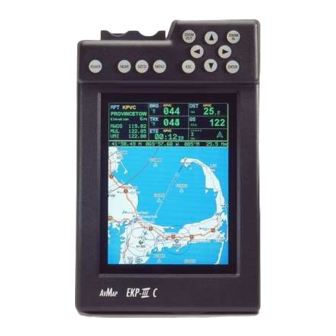
Fig. 1.2 - The EKP-III 1.3 FLYING START These pages provide a very brief overview of several of the EKP-III’s important features, the Main Menu, the Moving Map, GoTo flights and locating a Waypoint in the Database. It does not replace the User Manual, which should be read to get the fullest possible use from your EKP-III. -
Page 14: The Main Menu
C-MAP NT + C-CARD (if one is installed), its date of production, software name and version, library version followed by the Warning page. Press ‘ENTER’ to exit from the Warning page and enter the Moving Map mode. The Moving Map is the default state displaying the Moving Map screen and the Data Window. -
Page 15: Moving Map Icons
Auto Zoom mode will keep your present position, and your destination in the screen at all times. The screen will automatically zoom in as you get closer. To shut off this function, sim- ply select OFF. The Cursor Mode (OFF Selected) will allow you to move the map to any position to view data or details. -
Page 16: Goto
1.3.6 GOTO GoTo sets a 1-leg course from the present position to any location or selected Waypoint. To activate a GoTo Flight Plan move the cursor to the desired location or Waypoint and press ‘GOTO’. The GoTo menu box will open enabling you to activate the current cursor position or search the Database for a specific object to fly to. -
Page 17: The Basics
The Basics This chapter provides general information about the functions of the keys, inserting and removing data cartridges and entering data (connecting the EKP-III to power and using the antenna are described in Chapter 15). 2.1 THE KEYBOARD The EKP-III has 12 keys, which access and control features. Some keys perform different tasks based on the operation mode. -
Page 18: Turning The Ekp-Iii On And Off
The Near key Displays a list of the 20 nearest objects relative to fix position or cursor position if no fix is available. The Esc key Rejects an action, closes a window or activates Home or Auto Zoom mode. The Enter key Selects the desired option or confirms selection. -
Page 19: Turning Off
After a few seconds the Warning page is displayed, reminding you that the EKP-III is an aid to navigation and should be used with appropriate prudence. The electronic charts are not intend- ed to substitute for the official charts. Press ‘ENTER’ to open the Moving Map screen. 2.2.2 TURNING OFF ‘POWER’... -
Page 20: External Connections
>‘MENU’ 1 sec. + “SYSTEM SETUP” + ‘ENTER’ + “GENERAL SETUP” + ‘ENTER’ + “LAN- GUAGE” + ‘ENTER’ 2.5 EXTERNAL CONNECTIONS 2.5.1 INTERNAL/EXTERNAL GPS SOURCE The EKP-III has an internal GPS Receiver. Be sure the Fix Source is set to Internal GPS to receive data from this internal receiver. -
Page 21: Differential Input
The default setting is Off. The Output NMEA0183 messages are the following: APA, APB, BOD, BWC, GGA, GLL, HSC, RMA, RMB, RMC, VTG, WCV, XTE (see Appendix F for more details on NMEA sentences) BOD, BWC, GGA, GLL, HSC, RMA, RMB, RMC, VTG, WCV, XTE (see Appendix F for more details on NMEA sentences). -
Page 22: Down Or Up-Load Flight Plans & Tracks
2.5.4 DOWN OR UP-LOAD FLIGHT PLANS & TRACKS The EKP-III can also send and receive Flight Plans from the C-MAP PC-PLANNER NT + software program or another device compatible with it. This requires an optional power/data cable that can be purchased from your avionics dealer or C-MAP (see Fig. 2.5.4) for a proper connection to the device (see Fig. -
Page 23: Additional C-Cards
A data storage cartridge, called User C-CARD (see Par. 5.4), can be used to permanent- ly store your Flight Plans, Waypoints and Track, for later upload into the EKP-III. This data can also be shared with other AvMap plotters compatible with this feature. 2.6.1 INSERTING C-CARD Hold the C-CARD by the short inclined side so that you can see the C-MAP label. -
Page 24: Removing C-Card
NOTE C-CARD should be inserted or removed when the EKP-III is powered Off. Be sure to keep the slot free of moisture; it is NOT waterproof. While holding the EKP-III facing towards you, hold the C-CARD with the gold contacts toward the receiver and “C-MAP”... -
Page 25: System Setup Options
2.7 SYSTEM SETUP OPTIONS You may select how the EKP-III displays primary information (such as how time is displayed) from the System Setup Menu. >‘MENU’ 1 sec. + “SYSTEM SETUP” + ‘ENTER’ Refer to Chapter 13 for information about the System Setup Menu. 2.8 DATA ENTRY Information is keyed into the EKP-III when editing a Waypoint, entering a Flight Plan, using the calculator and searching the Database. - Page 26 EKP III USER MANUAL...
-
Page 27: The Moving Maps
The Moving Maps The Moving Map is the default state of the software. This mode displays the Moving Map screen and Data Window. The Moving Map displays map detail in Home, Auto Zoom or Cursor mode. The operation mode will determine the options available within the screen. The Data Window contains the navigation information pertaining to the active flight;... -
Page 28: Home (Screen Amplifier) Mode
3.1.2 HOME (SCREEN AMPLIFIER) MODE The Home mode (also called Screen Amplifier) is used to keep the fix position within the vis- ible map. The map is scrolled and redrawn automatically as your position moves. When this mode is active the cursor is hidden. When in Home mode, there will be no position line dis- played at the bottom of the Data Window. -
Page 29: Automatic Info
The Moving Map screen provides the option for a Data Window display for a user defined nav- igation information panel. This window is fixed at the top of the screen. During Cursor mode, an additional line is displayed at the bottom of this box with details on the cursor position. See Par. -
Page 30: Airspace Information
3.4.1 AIRSPACE INFORMATION Airspace Info will display information about the airspace within the cursor/position fix. The selected area(s) of airspace queried is highlighted. >‘ENTER’ + “AIRSPACE INFO” + ‘ENTER’ Like Automatic Info the window is opened in the top or bottom part of the screen. One window displays all airspace objects. -
Page 31: A > B Function
the screen. The EKP-III will store 10 radials. To project a radial, first select the object with the cursor, then: >‘ENTER’ + “PROJECT RADIAL” + ‘ENTER’ Using the cursor keys enter the Bearing and press ‘ENTER’. The Distance box is now active;... -
Page 32: Edit Waypoint
Add Waypoint: >Place the cursor at position + ‘ENTER’ + “ADD WAYPOINT” + ‘ENTER’ Edit Waypoint: >Place the cursor over Waypoint + ‘ENTER’ + “EDIT WAYPOINT” + ‘ENTER’ The Edit Waypoint box will appear. Using the cursor keys scroll through the alphanu- merics to create an eight character name, adjust the Latitude or Longitude or select an icon. -
Page 33: Moving Map Menu
To edit a flight plan on the moving map, be sure the flight plan is selected as the “Viewed” flight plan. (See Sec. 6.1.1). To insert a waypoint between two existing waypoints in the viewed flight plan, move the cursor over the leg to be edited: ‘ENTER’... -
Page 34: Auto Position Mode
The Flight Plan list will display, using the arrow keys, highlight the flight plan and press ‘ENTER’. Select an EMPTY flight plan if you do not want a flight plan to display on the Moving Map, or to create a new Flight Plan from the Moving Map. 3.5.1.1 AUTO POSITION MODE To set Auto Zoom or Auto Home mode: ‘MENU’... -
Page 35: Setup Data Fields
3.5.3 SETUP DATA FIELDS You can select the item to be displayed in each of the fields of the Data Window. The following Fig. 3.5.3 displays the options available. The fields selected for each window mode option (1-line, 2-lines, etc.) are independent; therefore, you can select different fields for each window view. >‘MENU’... -
Page 36: Default Datafields
NOTE The Dest: Wpt Info option requires 3 vertical fields for display; therefore, you can only select this option in a top field on the 3-line display or the top field in the HIS + Fields display. If you attempt to select this item in anoth- filed, system will... -
Page 37: Map Presentation Settings
Fig. 3.5.5 - 8 marks at the areas where the icon may appear 3.5.6 MAP PRESENTATION SETTINGS Map Presentation allows you to select the priority of the map display and color selections among AERO + TERRESTRIAL/AERONAUTICAL/MARINE settings. >‘MENU’ + “MAP PRESENTATION” + ‘ENTER’ The options are: Aero + Terrest, Aeronautical, Marine. - Page 38 3.5.8.1 VFR Settings The VFR Settings category relates to the aviation features found in the Navdata C-CARD. Airports: ON/OFF. The default setting is On. VOR: ON/OFF. The default setting is On. NDB: ON/OFF. The default setting is On. Intersections: ON/OFF. The default setting is On. Vertical Obstructions: ON/OFF.
-
Page 39: Lat/Lon Grid
other bathymetric areas are white. So, if the reference depth is 0, all areas are white, if it is 99.999 all areas are gray. The default setting is 33 FT. NOTE FOR THE EKP-III C The Depth Areas shown on the screen are filled with three different shades of blue. Selecting the Min and Max val- ues in the range of Depth Limit, there are three areas: [0, Min] colored with dark blue, [Min, Max] colored in blue and [Max, 15000] colored in light blue. - Page 40 Fig. 3.5.9 - Selective Display Settings EKP III USER MANUAL...
-
Page 41: Navigation & Location
Navigation & Location The Navigation and Location screen displays a full page of navigation information with loca- tion coordinates. To access from the Main Menu: >‘MENU’ 1 sec. + “NAV/LOCATION” + ‘ENTER’ 4.1 NAVIGATION & LOCATION DATA The Navigation data displayed in this window is based on the current Flight Plan leg or active Waypoint. - Page 42 NOTE Distances are measured horizontally. If the icon rotates 180° and points toward the bottom of the display, you are moving away from the destination. The numbers on either side of the CDI represent a full-scale deflection. To change the CDI scale press the left/right cursor keys. The EKP-III references navigation information to the next Waypoint in the active Flight Plan.
-
Page 43: Save Current Fix As User Waypoint
The Altitude (ALT), distance and velocity units of measure are selected from Units Setup in the System Setup Menu; the clock format (time and date) is selected from Time Format in Date & Time Setup, also in the Setup Menu (refer to Chapter 14). 4.2 SAVE CURRENT FIX AS USER WAYPOINT You can save your current position as a User Waypoint while viewing the Nav/Location page by pressing ‘ENTER’. -
Page 45: The His Screen
The HIS Screen The HSI screen presents the desired course to be flown and the current Track in a graphical format similar to the Horizontal Situation Indicator of an aircraft; using the compass rose as the center of the display. From Moving Map: >‘MENU’... -
Page 46: Hsi Menu
Course Deviation Indicator (CDI) scale is displayed at the bottom of the screen. Use the cur- sor keys up/down to change VSI scale among 250, 500 and 1000 FT. Use the cursor keys left/right to change CDI scale among 0.1, 0.5, 1, 2, 5 and 10 NM. The units of measure are selected from Units Setup in the System Setup Menu, (refer to Chapter 14). -
Page 47: Compass Orientation
>‘MENU’ + “DEFAULT DATA FIELDS” + ‘ENTER’ 5.2.4 COMPASS ORIENTATION The Compass Orientation allows you to set the orientation mode for the HSI compass to either North-up or Track-up. The Compass Orientation controls the rotation such that track head- ing (Track-up or North-up) always appears at the top of the screen. >‘MENU’... - Page 48 EKP III USER MANUAL...
-
Page 49: Flight Plan
Flight Plan >‘MENU’ 1 sec + “FLIGHT PLAN” + ‘ENTER’ The Flight Plan mode allows you to create a Flight Plan with User Points, Temporary Waypoints or Jeppesen object as Waypoints. Flight Plans can be entered on the Moving Map (see Par. -
Page 50: Viewed Flight Plan
6.1 VIEWED FLIGHT PLAN When you enter the Flight Plan Page, the information appearing on the screen is for the cur- rent “Viewed” Flight Plan. The Flight Plan name will appear at the top of the page. All actions within the Flight Plan menu are related to the currently “Viewed” Flight Plan. -
Page 51: Naming A Flight Plan
Be sure the Flight Plan you would like to activate is the “Viewed” Flight Plan appear- ing on the screen. If it is not, you will need to select it from the Flight Plan menu: >‘MENU’ 1 sec. + “FLIGHT PLAN” + ‘ENTER’ + ‘MENU’ + “VIEWED FP” + ‘ENTER’ + “FP ”... -
Page 52: Reverse A Flight Paln
‘MENU’ 1 sec. + “FLIGHT PLAN” + ‘ENTER’ + ‘MENU’ + “CLEAR FP” + ‘ENTER’ A Warning window will appear to confirm deletion: press ‘ENTER’ to confirm, ‘ESC’ to abort. 6.6 REVERSE A FLIGHT PALN The Flight Plans stored in the EKP-III memory can be automatically reversed by: >‘MENU’... -
Page 53: Nearest Search For Goto Flight Plan Activation
6.8 NEAREST SEARCH FOR GOTO FLIGHT PLAN ACTIVATION Pressing ‘NEAR’ at any time will provide a list of the 20 Nearest Database objects. The first page to appear will be the last chosen category of data. To select another category of data, press ‘MENU’... - Page 54 EKP III USER MANUAL...
-
Page 55: The Global Positioning System
The Global Positioning System The Global Positioning System (GPS) is a constellation of satellites that orbit the earth twice a day, transmitting precise time and positioning information to anywhere on the globe, 24 hours a day. The system was designed and deployed by the U.S. Department of Defense to provide continuous, worldwide positioning and navigation data to U.S. -
Page 56: Gps Receiver Specifications
On the bottom half of the screen (see previous Fig 7.1) there is a polar representation of the Azimuth and Elevation of the satellites used to compute a position fix. The Elevation is the height of the satellite above the horizon, with 5° (lowest) near the horizon and 90°... -
Page 57: Accuracy
becomes unavailable, the receiver knows exactly where to find the best possible replacement). Three satellites are required for two-dimension positioning (which determines position only) and four satellites are required for three-dimension positioning (to determine position and elevation). 7.3.1 ACCURACY In general, an SPS receiver can provide position information with an error of less than 25 Meters and velocity information with an error of less than 5 Meters per second. -
Page 58: Monitoring & Controlling The Gps
corrected data. Care must be taken to ensure that the DGPS receiver and the GPS receiver are compatible for this procedure to be successful. 7.3.4 MONITORING & CONTROLLING THE GPS The Global Positioning System is monitored and controlled by the U.S. Air Force, which is responsible for updating and maintaining exact satellite position and signal data accuracy. -
Page 59: Waypoint & Database
Waypoint & Database The EKP-III uses three types of Waypoints: Jeppesen Waypoints are contained in the C-CARD™ and include Airport, VOR, NDB and Intersection Waypoints. Each of these Waypoints is displayed on the Moving Map by an icon. These Waypoints can be searched in the Database Menu and identified on the Moving Map with Quick Info or Full Info. -
Page 60: User Waypoints - Moving Map
8.1 USER WAYPOINTS – MOVING MAP 8.1.1 CREATING USER WAYPOINTS – MOVING MAP From the Moving Map the User Waypoint is a saved cursor position. To create a User Waypoint at the cursor position: >‘ENTER’ + “ADD WAYPOINT” + ‘ENTER’ A name is automatically assigned in the format “USRxxx”, where “xxx”... -
Page 61: User Waypoints - Database Methods
8.2 USER WAYPOINTS – DATABASE METHODS 8.2.1 CREATING USER WAYPOINTS – DATABASE METHODS A User Waypoint can be entered manually into the User Database Menu by selecting a display icon, entering a name (up to 8 characters) and keying in the desired Coordinates. To enter a Waypoint via the Database Menu page from the Moving Map: >‘MENU’... -
Page 62: Database Menu
8.3.1 DATABASE MENU To access the main Database menu from the Moving Map: >‘MENU’ 1 sec + “DATABASE” + ‘ENTER’ Options are: Airports, VOR, NDB, Intersections, User Waypoints. A window shows the different categories of Database items within the EKP-III. Highlight the category to be searched and press ‘ENTER’. -
Page 63: User C-Card
8.3.1.2 Displaying Sunrise and Sunset Information With the Airport selected on the Database page, press ‘NEAR’ to display the Sun/Moon informa- tion for the airport. If a GPS fix is present, the information will automatically display. If no GPS fix is present, or you would like to see the information for another day, press ‘ENTER’ to activate the SUN/MOON INFO box and select the date. -
Page 64: Saving Data To User C-Card
>‘MENU’ 1 sec + “DATABASE” + ‘ENTER’ + “USER C-CARD” + ‘ENTER’ + “FORMAT” + ‘ENTER’ A warning window is shown, select “YES” and press ‘ENTER’ to confirm the format- ting (select “NO” otherwise). Once finished, your User C-CARD is formatted and ready to use. Be sure to label it. The label will remind you that the User C-CARD has been formatted and contains data you may not want to erase. -
Page 65: Deleting Data From User C-Card
8.4.4 DELETING DATA FROM USER C-CARD Just as you may need to saving files, you may also need to remove old or unnecessary files to clean up your User C-CARD. The deleting function erases a file from User C-CARD. Remember though that this operation permanently erases the file. Before you start the deleting procedure, insert the User C-CARD (see Par. - Page 66 EKP III USER MANUAL...
-
Page 67: Approach Data Procedures
Approach Data Procedures WARNING: The EKP III C is not certified for use as the only navigation device during Instrument Flight Rules as established by the FAA. Instrument approach points displayed in the unit are for information only and do not establish authority for a pilot to fly the IFR approach procedure in actual instrument flying conditions. -
Page 68: Approach From Flight Plan Database
(Note: The white approach bearings will disappear once the screen redraws itself). 9.2 APPROACH FROM FLIGHT PLAN DATABASE Refer to Chapter 6 for Flight Planning. Flight Plan mode allows the pilot to plan and activate up to ten flight plans with up to 100 indi- vidual legs each. -
Page 69: Select Approach For Goto
To remove desired approach ‘MENU’ + ‘MENU’ + “FLIGHT PLAN” + ‘ENTER’ + ‘MENU’ + “REMOVE APPROACH” + ‘ENTER’. 9.3 SELECT APPROACH FOR GOTO If a ‘GOTO’ to an airport is active, pressing “GOTO” from the map will display the GOTO menu (regardless of your cursors position). - Page 70 Selecting “Remove Approach” removes the approach waypoints from the GOTO destination replacing them with the corresponding airport waypoint (that was originally selected). Activating a GOTO with an Approach from database If you are in the airports database page ‘MENU’ + ‘MENU’ + “DATABASE” + “AIRPORTS” and the screen is displaying approach information, by pressing ‘GOTO’...
-
Page 71: Calculator
Calculator The Calculator functions assist the user in preflight and in-flight calculations for Vertical Navigation, Wind and Fuel consumption. In addition, clock functions and trip data can be found in this menu. The Calculator uses GPS data and user data for computations. All Calculator functions are based on the active Flight Plan. -
Page 72: Elapsed Timer
based on the GPS data. If the GPS fix is lost during this mode, the timer will display dashes in the right hand column. The time calculation will continue to work in the background. >‘MENU’ 1 sec. + “CALCULATOR” + ‘ENTER’ + “COUNTDOWN TIMER” + ‘ENTER’ A box will appear in the right hand column allowing you to set the hours, minutes and seconds. -
Page 73: Vertical Navigation
Flying Avg: Speed values above 35 knots divided by flying time. Overall Avg: Speed values divided by Partial Distance. Maximum Speed: Fastest speed reached Current Speed: Current GPS speed. Flying Time: Total time when speed is greater than 35 knots. Stopped Time: Total time unit was on with a GPS fix and speed was less than 2 knots. - Page 74 function (the units of measure used for the values entered here are selected from Units Setup menu in the System Setup Menu, see Par. 13.5). This feature requires that a Flight Plan be activated. >‘MENU’ 1 sec.+ “CALCULATOR” + ‘ENTER’ + “VERTICAL NAVIGATOR” + ‘ENTER’ User data is entered in the fields at the bottom half of the screen.
-
Page 75: Wind Calculation
Vertical Navigation can be activated (On) only if a Flight Plan is active (destination present). Destination point for Vertical Navigation is the last point of the Route or destination of GoTo mode. Prior to the Descent Point being reached the Distance To Go displays TO, Time To Go to Descent point and Descent Rate from the current position. -
Page 76: Fuel Consumption
NOTE This function works best when the airplane is straight and level. Wind Calculation is a full screen page with the following structure: The EKP-III computes wind velocity and direction from the information entered above and from the current Ground Speed, Track and Altitude, which are derived from GPS data. - Page 77 To set Fuel Consumption parameters use ‘ENTER’ to edit the selected field (a box appears around the active field) and use the cursor keys to move between fields. Press ‘ESC’ to return to the Calculator Menu. If your current Ground Speed is over 20 Knots, the EKP-III will display “Actual GS” and will not allow you to edit the value.
- Page 78 Fig. 10.6a - Sample Calculation EKP III USER MANUAL...
-
Page 79: The Checklists
The Checklists The EKP-III provides a checklist of standard procedures for Engine Start, Ground Check, Pre-Take-off, and Landing. NOTE Your aircraft may have additional items that require checking for each procedure. Consult your aircraft manual for a complete list. >‘MENU’ 1 sec. + “CHECKLISTS” + ‘ENTER’ 11.1 ENGINE START >... -
Page 80: Ground Check
list are not checked upon exit a warning message appears on the screen that states the check- list has not been completed. Press any key to accept. 11.2 GROUND CHECK > ‘MENU’ 1 sec. + “CHECKLISTS” + ‘ENTER’ + “GROUND CHECK” + ‘ENTER’ After pressing ‘ENTER’... -
Page 81: Simulator
Simulator The built-in Simulator function allows you to become proficient in the use of the EKP-III before ever taking it into the cockpit. No current position fix is required because the EKP-III simulates position data internally. The EKP-III simulates flight in two ways: a straight flight path or following a selected route. -
Page 82: Simulating Route Mode
12.2 SIMULATING ROUTE MODE To Simulate the flight of an existing Flight Plan, be sure the flight is the “Viewed” Flight Plan (see Par. 6.1) Then enter the Simulator Menu and select the parameters of “Speed” and “Flight Plan Mode”. >‘MENU’... -
Page 83: The Communication
The Communication The Communications Menu contains options that control the GPS data input: >‘MENU’ 1 sec. + “COMMUNICATIONS” + ‘ENTER’ 13.1 NMEA OUTPUT The EKP-III can be attached to external equipment that accepts GPS data input. (see Chapter 15 for wiring.) Once attached, the output of NMEA formatted data can be enabled in the fol- lowing manner: >‘MENU’... -
Page 84: Waypoints Upload Downloads
13.2 WAYPOINTS UPLOAD DOWNLOADS The Upload Waypoint function allows the unit to receive a Waypoint from the serial port using the NMEA0183 $WPL sentence (see Appendix E): >‘MENU’ 1 sec. + “COMMUNICATIONS” + ‘ENTER’ + “WAYPOINTS UPLOAD” + ‘ENTER’ The Download Waypoint function allows the unit to send the current Waypoints to the serial port using the NMEA0183 $WPL sentence (see Appendix E): >‘MENU’... -
Page 85: The System Set-Up Menu
The System set-up Menu The System Setup Menu allows the user to change how the EKP-III displays information. System Setup options are arranged in sub-menus. For example, all options that relate to the Fix functions are in Fix Setup sub-menu and all options related to time or date are in Date Time Setup. >‘MENU’... -
Page 86: General Set-Up
14.1 GENERAL SET-UP The General Setup sub-menu controls the EKP-III settings. >‘MENU’ 1 sec.+ “SYSTEM SETUP” + ‘ENTER’ + “GENERAL SETUP” + ‘ENTER’ 14.1.1 Beeper The EKP-III makes a beep with each key press, warning or alarm message. >‘MENU’ 1 sec. + “SYSTEM SETUP” + ‘ENTER’ + “GENERAL SETUP” + ‘ENTER’ + “BEEPER”... -
Page 87: Fix Set-Up
14.2 FIX SET-UP The Fix Setup sub-menu contains options relating to GPS data input and display. >‘MENU’ 1 sec. + “SYSTEM SETUP” + ‘ENTER’ + “FIX SETUP” + ‘ENTER’ 14.2.1 FIX SOURCE The EKP-III uses positioning information provided by the internal GPS-receiver or by an external NMEA 0183, external Air Data, or External RNAVdata string. -
Page 88: Course Predictor
14.2.5 COURSE PREDICTOR The EKP-III will display a line with a circle at the end to indicate the position your aircraft will reach at the set time, based on current direction of travel and speed. This is continuously updated to account for changes. >‘MENU’... -
Page 89: Waypoint Alarm Radius
After pressing ‘ENTER’ a box will appear with 00. Using the cursor keys select the number desired and press ‘ENTER’. The default setting is Off (00). 14.3.3 WAYPOINT ALARM RADIUS Specifies the radius of a circle around the User Waypoint: when your aircraft reaches a point within this circle an alarm sounds and the Waypoint Alarm box apprears on the screen. -
Page 90: Clear Event Log
14.3.6 CLEAR EVENT LOG Clears the Event Log memory and starts new: >‘MENU’ 1 sec. + “SYSTEM SETUP” + ‘ENTER’ + “ALARM SETUP” + ‘ENTER’ + “CLEAR EVENT LOG” + ‘ENTER’ After pressing ‘ENTER’ a window appears: press ‘ENTER’ to confirm deletion (or ‘ESC’... -
Page 91: Remaining Track
14.4.4 REMAINING TRACK The remaining track memory is displayed on the Track Setup Menu page. The number dis- played will be points, time, or distance based on the recording step selection. 14.5 UNITS SET-UP This sub-menu contains the various options that define how the EKP-III displays units of measurement. -
Page 92: Fuel Unit
14.5.5 FUEL UNIT Fuel units are used in the Fuel Consumption Calculator. >‘MENU’ 1 sec. + “SYSTEM SETUP” + ‘ENTER’ + “UNITS SETUP” + ‘ENTER’ + “FUEL” + ‘ENTER’ You may select Gallons (GAL), Liters (LIT), Kilograms (KG), Pounds (LB) or British Gallons (BGAL). -
Page 93: Date & Time Set-Up
The EKP-III displays dates as MM/DD/YY – Month/Day/Year or DD/MM/YY – Day/Month/Year. The default setting is MM/DD/YY. 14.7 COLORS SET-UP – ONLY EKP III C >‘MENU’ 1 sec. + “SYSTEM SETUP” + ‘ENTER’ + “COLORS SETUP” + ‘ENTER’ EKP III USER MANUAL... -
Page 94: Data Window Colors
14.7.1 DATA WINDOW COLORS This setting controls the background color of the data window display. >‘MENU’ 1 sec. + “SYSTEM SETUP” + ‘ENTER’ + “COLORS SETUP” + ‘ENTER’ + “DATA WINDOW COLOR” The options are Dark or Light. The default is Dark. 14.7.2 TRACK COLOR The color of the track history display line can be selected from this menu setting. -
Page 95: Operating Requirements
Operating Requirements The EKP-III must be connected to a 10–35 V DC power source and the antenna requires a clear view of the sky in order to operate. Fig. 15 - Power and I/O Connector NOTE The cable that ends with wires is available as an optional part. Please contact your local C-MAP office for details. -
Page 96: External Wiring
15.1 EXTERNAL WIRING External Power The EKP-III has a detachable power cable. After connecting the power cable to the EKP-III via the 7 pin conxall connector, insert the power cable into the aircraft’s cigarette lighter or the optional battery pack. External Equipment External equipment can be connected to the EKP-III through an optional data cable. -
Page 97: Dimensions
Use the elastic strap provided to secure the EKP-III to your leg. Position the elastic strap around your leg with the long looped strip on top. Fasten with the hook and loop closure at each end of the strap. Hold the EKP-III over the strap on your leg and lower into place. Press down a little to be sure the strips are secure. - Page 98 15.5 TYPICAL CONNECTION – POWER & I/O CONNECTOR Fig. 15.5 - EKP-III Typical Connection EKP III USER MANUAL...
-
Page 99: Troubleshooting
15.6 TROUBLESHOOTING The following is a brief guide to some of the problems you may experience while using the EKP-III with common solutions. 15.6.1 POWER No Power — The power connections are loose or not fully engaged. Make sure all Power Cable connections are secure. -
Page 100: When Nothing Else Works
messages in the correct format. Refer to the external device’s user guide to determine the cor- rect message format. Check the Installation Settings menu and make any necessary changes. The EKP-III may not be properly connected to the external device. Check all connections to be sure they are correctly made and secure. -
Page 101: System Test
Fig. 15.6.4 - About page If it is necessary to return your EKP-III for repair, you must obtain a return authorization (RA) number from C-MAP Aviation prior to shipping the system. Include with the EKP-III a description of the problem, your RA number, and your name and address. If your return ship- ping address is different, please include it. -
Page 102: C-Card Menu
and press ‘ENTER’ to select RAM Test or RAM Clear. RAM Test ‘ENTER’ on RAM Test to verify the integrity of the RAM. If the message “ERROR” appears the RAM is physically damaged. RAM Clear ‘ENTER’ on RAM Clear to to activate, press ‘ENTER’ again to confirm (at this time if you do not wish to clear RAM press ‘ESC’). -
Page 103: Serial Ports
Internal Map Test To test the Internal Map Database. If it is corrupted the message “Faulty” is shown (please contact your local dealer). C-CARD Test To test the C-CARD. There are the following possible situations: 1. If there is a C-CARD inserted in the slot and there is not a malfunction, the name of the C-CARD zone and the message “OK”... - Page 104 Change Parameters To change the parameters of the serial interface. This menu allows to select the Port (Signal Source) between UART0 or UART1, the Baud Rate between 4800 or 9600, the Data Bits (Word Length) between 7 or 8, the Parity between EVEN, ODD or NONE, the Stop Bits between 1 or 2, the Polarity between “+”...
-
Page 105: Appendix A Terms
Appendix A Terms THIS SECTION EXPLAINS THE TERMS THAT YOU MAY FIND UNFAMILIAR ACQUISITION Occurs when the EKP-III locates a signal and collects data from a satellite. AIRPORT DATABASE A series of files of airport positions (described near the geographical center of the airport and as defined by ICAO), with runways, frequencies (with sectors) and services available information. - Page 106 ELEVATION Altitude above sea level (MSL). Usually refers to field Elevation of an airport. Also refers to a satellite’s height above the horizon. EPHEMERIS DATA Data on the specific location of a satellite that is collected from that satellite when it is first located and is periodically updated while the satellite is being tracked.
- Page 107 NAUTICAL MILE - A distance measurement equal to 6,076 feet or 1.15 Statute Miles. Also equal to one Minute of Latitude. NMEA NATIONAL MARINE ELECTRONICS ASSOCIATION - Professional organization that defines and maintains the standard serial format used by marine electronic navigation equipment and computer interfaces. NMEA format has been adopted by parts of the avionics industry.
-
Page 108: Appendix B - Operational Command Tree
APPENDIX B Operational Command Tree EKP III USER MANUAL... -
Page 109: Appendix C Map Datum
Appendix C Map Datum A map datum is a mathematical description of the earth or a part of the earth and is based on the ellipsoid or the arc of an ellipsoid that most closely represents the area being described. In addition, the datum is centered at a specific location (the datum origin). -
Page 110: Appendix D Icao Codes
Appendix D ICAO codes The EKP-III Database of airports is drawn from the system of ICAO (International Civil Aviation Organization) identifiers. Unlike the IATA (International Airline Transport Association) identifiers seen on charts and luggage tags, the ICAO codes minimize the possi- bility of duplicate identifiers and allow pilots to identify an airport’s region and nearby large city. - Page 111 Antarctica (Aus/NZ) EKP III USER MANUAL...
- Page 112 ICAO CODE NAME Greenland Iceland Miquelon Island/St Pierre Island (Canada) Canada Algeria Benin Burkina Faso Accra/Ghana Ivory Coast Nigeria Niamey/Niger Tunisia Togo Belgium Germany Estonia Finland Shanwick Oceanic/United Kingdom Netherlands Ireland Denmark/Faroe Islands Luxembourg Norway Poland Sweden Germany Bophuthatswana/Ciskei/Johannesburg/Namibia/ South African Republic/Southwest Africa/Transkei/Venda Botswana Brazzaville/Congo Swaziland...
- Page 113 ICAO CODE NAME Futuna Islands/Wallis Islands American Samoa/Western Samoa French Polynesia/Society Islands/Tuamotu Islands Vanuatu New Caledonia New Zealand Afghanistan Bahrain Jedda/Saudi Arabia Iran Jordan Kuwait Lebanon United Arab Emirates Oman Pakistan Iraq Syria Qatar Oakland OCTA Alaska Kiribati Guam/Mariana Islands Hawaii Johnston Atoll Marshall Islands...
-
Page 114: Appendix E - C-Map Aviation Cartridge Options
Appendix E C-MAP Aviation Cartridge Options The EKP-III displays land cartography and navigational data from C-MAP data cards. The sys- tem is designed with land cartography internal to the hardware and two C-CARD slots for addi- tional external data. Following are the data options for the EKP-III. CONTINENTAL NAVDATA Jeppesen Database including airport, VOR, NDB, Intersection and airspace information. -
Page 115: Appendix F C-Map Data Transfer
Appendix F C-MAP Data Transfer THE BI-DIRECTIONAL DATA PORT OUTPUTS AND INPUTS NMEA DATA. NMEA MESSAGES SENT/RECEIVED AT 48008N1, ARE DEFINED AS FOLLOWS: Autopilot Sentence “A” contains navigation receiver warning flag status, cross-track-error, Waypoint arrival status and initial bearing from origin Waypoint to the destination Waypoint for the active navigation leg of the journey. -
Page 116: Index
INDEX ACQUISITION ...105 AERO...11, 32, 37 AERONAUTICAL ...10-11, 29, 37 AIR ROUTE TRAFFIC CONTROL CENTER...105 AIRPORT DATABASE ... 62-63, 105 AIRSPACE ...11, 27, 30, 37-38, 89, 107, 114 ALARM ...31, 60, 71, 86, 88-90 ALMANAC ...56, 58, 105 ALT...43, 46, 56, 75, 105 ALTITUDE...11, 30, 42-43, 46, 73-76, 81-82, 89, 91, 105-107 APPROACH ...57, 67-70, 107 APT ...32... - Page 117 KM ...11, 91 KNOTS ...73, 77, 87, 91, 100, 106 LAND...11, 37-38, 106-107, 114 LANDMARKS...11, 38, 106 LAT/LON...11, 27, 39, 42, 60, 105-106, 109 LATITUDE...32, 92, 105-107, 115 LOCATION..11, 14, 16, 29, 41-43, 55-56, 93, 96, 105-107, 109-110, 115 LONGITUDE...32, 92, 105-106, 115 LORAN...106, 115 MAGNETIC NORTH ...105-106 MARINE ...11, 37-38, 105, 107...
-
Page 118: Warranty
In the event of a defect, AvMap, at its option, will repair or replace the product with no charge to the purchaser for parts or labor. The repaired or replaced product will be warranted for ninety (90) days from the date of return shipment, or for the balance of the original warranty, whichever is longer.
Need help?
Do you have a question about the EKP III C and is the answer not in the manual?
Questions and answers