Table of Contents
Advertisement
Quick Links
Advertisement
Table of Contents

Subscribe to Our Youtube Channel
Related Manuals for SMC Networks IZH10 Series


Summary of Contents for SMC Networks IZH10 Series
- Page 1 No.SFOD-OML0002-A PRODUCT NAME Handheld Electrostatic Meter MODEL/ Series IZH10...
-
Page 2: Table Of Contents
Table of Contents Safety Instructions Model Indication Method Summary of Product parts Definition and terminology Assembly Setting / Adjustment Procedure Function settings Troubleshooting Specification Specifications Characteristics graph (for reference) Dimensions No.SFOD-OML0002-A... -
Page 3: Safety Instructions
Safety Instructions These safety instructions are intended to prevent hazardous situations and/or equipment damage. These instructions indicate the level of potential hazard with the labels of "Caution", "Warning" or "Danger". They are all important notes for safety and must be followed in addition to International standards (ISO/IEC), Japan Industrial Standards (JIS) and other safety regulations *1) ISO 4414: Pneumatic fluid power - - General rules relating to systems. - Page 4 Caution 1. The product is provided for use in manufacturing industries. The product herein described is basically provided for peaceful use in manufacturing industries. If considering using the product in other industries, consult SMC beforehand and exchange specifications or a contract if necessary. If anything is unclear, contact your nearest sales branch.
- Page 5 Operator ♦This operation manual is intended for those who have knowledge of machinery using pneumatic equipment, and have sufficient knowledge of assembly, operation and maintenance of such equipment. Only those persons are allowed to perform assembly, operation and maintenance. ♦Read and understand this operation manual carefully before assembling, operating or providing maintenance to the product.
- Page 6 ■NOTE ○Follow the instructions given below when designing, selecting and handling the product. ●The instructions on design and selection (installation, wiring, environment, adjustment, operation, maintenance, etc.) described below must also be followed. ∗Environment •Avoid using in a place where noise (electromagnetic wave and surge) is generated. This can result in malfunction (display of incorrect value), deterioration and damage of internal elements.
-
Page 7: Model Indication Method
Model Indication how to order ○Applicable body IZH10 - Option Model No. Content No option High voltage measuring handle ○Accessories The ground wire and soft case are included with all products. •Ground wire (1.5 m) •Soft case IZH-A-01 IZH-B-01 ○Option •High voltage measuring handle IZH-C-01 No.SFOD-OML0002-A... -
Page 8: Summary Of Product Parts
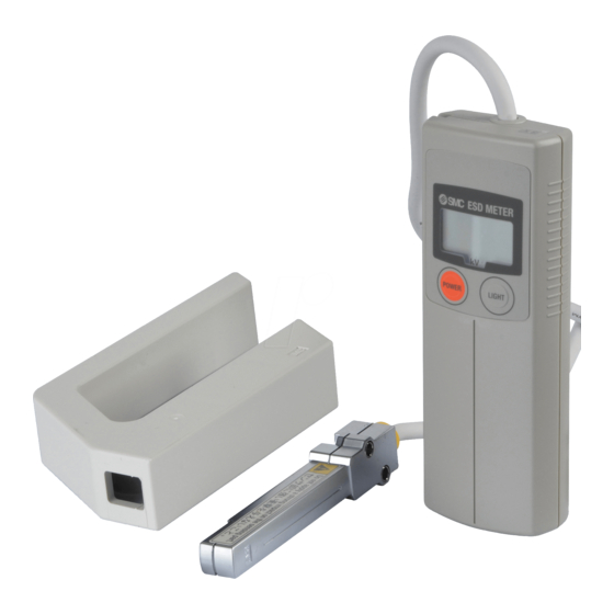
Summary of Product parts ○Names of individual parts •Display •Sensor No.SFOD-OML0002-A... -
Page 9: Definition And Terminology
■Definition and terminology Terms Meaning A function that turns off the power supply automatically when no Auto power-OFF (function) buttons are pressed for 5 minutes after the power supply is turned on. Auto power-OFF extension (function) A function that extends the time of auto power-off to 15 minutes. Back light A light that makes the display visible in a dark environment. -
Page 10: Assembly
Assembly ○Insertion of batteries Slide the lid of the case to open and insert the batteries into it. The type of battery that can be used is 2 A alkali dry cell battery (LR6). When inserting the batteries, pay attention to the polarities and insert them in the correct direction. After insertion, ensure the lid is closed for use. -
Page 11: Setting / Adjustment
Setting / Adjustment ■Procedure 1. Insert the batteries in place. 2. Connect the ground wire. Connect the ground wire to a place where is connected to an external protective earthling system. The place where the ground wire is to be connected is as shown below. 3. -
Page 12: Function Settings
■Function settings ○Power ON When the is pressed with the power supply off, the power supply will be turned on. All indications are displayed for 1 s. after the power supply is turned on. ○Power OFF When the is pressed for 3 s. or more with the power supply on, the power supply will be turned off. Also, no button operation for a certain period will turn off the power supply. - Page 13 ○Peak/Bottom hold value When the is pressed with the power supply on, the indication will be changed to instantaneous value, peak hold value, bottom hold value and instantaneous value, in that order. ∗: Release the after "P" or "b" is displayed so as not to turn off the power supply. •Peak hold value The maximum charged potential and "P"...
- Page 14 ○Battery low When the battery voltage lowers, "L" will be displayed. The display will be done in a different way depending on how much battery is left. Display Content The battery is low. L (Flashing) Prepare for replacement with a new one. The battery is very low.
-
Page 15: Troubleshooting
Troubleshooting ○Troubleshooting When the product is found to have operation failure, use the following flowchart to identify the cause of failure. If there is no cause applicable to the failure, consider the product itself has broken. The product can break for reasons in the operating environment. - Page 16 ○Cross reference for troubleshooting Reference Problem Possible cause Investigation method Countermeasure Check the orientation of battery as The battery is inserted Check the orientation of shown in the case and if it is incorrectly. battery. There is no incorrect, reinsert the battery. display.
- Page 17 ○Error indication function Error Name Error display Error Type Troubleshooting Method A charge over ±5%F.S. of the default zero point is given to the sensor during zero clear operation. (Er1) Zero clear Return to a condition without charge, ∗: After approx. 1 s. error display, the sensor error and retry zero clear operation.
-
Page 18: Specification
Specification ■Specifications Item IZH10 Rated charge amount range ±20.0 kV Minimum display unit 0.1 kV (±1 kV to 20 kV), 0.01 kV (0 to ±0.99 kV) Measuring distance 50 mm (between the detection port and measured target) ∗ 1 ∗ 2 Power supply 1.5 VDC 2 A alkali dry cell battery (2 pcs.) (continuously used for 15 hours Display accuracy... -
Page 19: Dimensions
■Dimensions •Display •Sensor -18- No.SFOD-OML0002-A... - Page 20 Revision history A: Change format Note: Specifications are subject to change without prior notice and any obligation on the part of the manufacturer. © 2008-2010 SMC Corporation All Rights Reserved No.SFOD-OML0002-A...
Need help?
Do you have a question about the IZH10 Series and is the answer not in the manual?
Questions and answers