Table of Contents
Advertisement
Quick Links
Advertisement
Table of Contents

Related Manuals for SMC Networks IZE11


Summary of Contents for SMC Networks IZE11
- Page 1 No.SFOD-OMO0004-B PRODUCT NAME Electrostatic Sensor Monitor MODEL/ Series IZE11...
-
Page 2: Table Of Contents
Table of Contents Safety Instructions Model Identification and How to Order Summary of Product parts Mounting and Installation Installation Wiring Setting Measurement mode Function selection mode Default setting F0 Select connect sensor F1 Operation of OUT1 F2 Operation of OUT2 F3 Measured distance setting F4 Setting of switch output response time F5 Select analog output filter... -
Page 3: Safety Instructions
Safety Instructions These safety instructions are intended to prevent hazardous situations and/or equipment damage. These instructions indicate the level of potential hazard with the labels of "Caution", "Warning" or "Danger". They are all important notes for safety and must be followed in addition to International 1) standards (ISO/IEC) and other safety regulations. - Page 4 Caution The product is provided for use in manufacturing industries. The product herein described is basically provided for peaceful use in manufacturing industries. If considering using the product in other industries, consult SMC beforehand and exchange specifications or a contract if necessary. If anything is unclear, contact your nearest sales branch.
- Page 5 Operator This operation manual is intended for those who have knowledge of machinery using pneumatic equipment, and have sufficient knowledge of assembly, operation and maintenance of such equipment. Only those persons are allowed to perform assembly, operation and maintenance. Read and understand this operation manual carefully before assembling, operating or providing maintenance to the product.
- Page 6 ■NOTE ○Follow the instructions given below when designing, selecting and handling the product. ●The instructions on design and selection (installation, wiring, environment, adjustment, operation, maintenance, etc.) described below must also be followed. Product specifications Operate the monitor with the specified voltage. Operation with a voltage beyond specifications can cause malfunction or damage of the monitor.
- Page 7 The direct-current power supply to combine should use UL authorization power supply which is the class 2 power supply based on UL 1310 or the power supply is using the transformer of a class 2 based on UL 1585. Environment Do not use the product in an atmosphere containing corrosive gas, chemicals, seawater, water or vapor, or in a place where there is a possibility of adhesion of those substances to the product.
-
Page 8: Model Identification And How To Order
Model Indication and How to Order ○Options/Part number Description Part number Remarks Power and output lead wire ZS-28-A Length 2 m Bracket ZS-28-B With M3x5 L (2 pcs.) Connector for sensor lead wire ZS-28-C 1 pc. Panel mount adapter ZS-27-C With M3x5 L (2 pcs.) Panel mount adapter + Front protective cover ZS-27-D... -
Page 9: Summary Of Product Parts
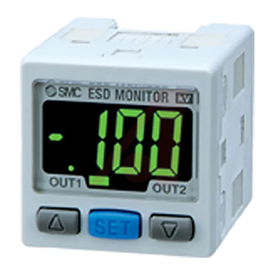
Summary of Product parts ○Names of individual parts Output (OUT1) display (Green): Lit when OUT1 is ON. Output (OUT2) display (Red): Lit when OUT2 is ON. LCD display: Displays the current status of charged potential, set mode condition and error code. Four display modes can be selected display always in red or green only, or changing from green to red linked to output, or changing from red to green. - Page 10 ○Options Power and output lead wire (2 m): ZS-28-A Connector for sensor lead wire (1 pc.): ZS-28-C Bracket with set screws M3x5 L (2 pcs.): ZS-28-B Panel mount adapter with set screws M3x8L (2 pcs.): ZS-27-C Panel mount adapter with set screws M3x8L (2 pcs.) + Front protective cover: ZS-27-D Front protective cover: ZS-27-01...
-
Page 11: Mounting And Installation
Mounting and Installation ■Installation ○Mounting ●Mount the optional bracket and panel mount adapter to the controller. ○Mounting by bracket ●Fix the bracket to the controller with the set screws M3x5 L (2 pcs.) as attached. ●The tightening torque of the set screws must be 0.5 to 0.7 Nm. ○Mounting by panel mount adapter ●Fix the panel mount adapter to the controller with the set screws M38 L (2 pcs.) as attached. -
Page 12: Wiring
■Wiring ○Connection Connections should only be made with the power supply turned off. Use separate routes for the Electrostatic Sensor Monitor wiring and any power or high voltage wiring. Otherwise, malfunction may result due to noise. Ensure that the FG terminal is connected to ground when using a commercially available switch-mode power supply. - Page 13 ○Connector Connecting/Disconnecting When connecting the connector, insert it straight onto the pin holding the lever and connector body between fingers and lock the connector by pushing the lever claw into the square groove in the housing until connector clicks. When disconnecting the connector, push down the lever by thumb to disengage the lever claw from the square groove.
- Page 14 ○Internal circuit and wiring example Output specification When the lead wire with SMC power and output lead wire (Model: ZS-28-A) is used, the colors of wire (Brown, Black, White, Gray, Blue) will apply as shown on circuit diagram. IZE110 NPN open collector output: 2 outputs Max.
-
Page 15: Setting
Setting ○Setting procedures ○Initial display Item Display Content IZE11 series Product type NPN open collector output Switch output type PNP open collector output Voltage output (1 to 5 V) Analog output type Current output (4 to 20 mA) -14- No.SFOD-OMO0004-B... -
Page 16: Measurement Mode
■Measurement mode Detect charged potential and perform display and switch operation. Setting change and setting of other functions are available depending on purpose. List of output mode The following is given using OUT1 as an example. The descriptions for OUT2 are the same as those for OUT1, under the conditions that [P_1] should be replaced by... - Page 17 ○Easy setting Set ON and OFF point of switch output. Switch turns ON when charged potential exceed set value. Switch turns OFF when charged potential is lowered by more than hysteresis. (This is an example when the switch output is normal output with hysteresis mode) Electrostatic Sensor Monitor is set at ex-factory so that it turns ON with OUT1 at +0.2 kV and OUT2 at -0.2 kV.
- Page 18 3. Press the button to change the set value. button is for increase and the button is for decrease. Press the button once to increase by one figure and press it continuously to keep set figure increased. Press the button once to decrease by one figure and press it continuously to keep set figure decreased.
-
Page 19: Function Selection Mode
■Function selection mode In measurement mode, press the button for 2 seconds or longer to display [F 0]. Show the display of function setting to be changed, [F Press the button for 2 seconds or longer in function selection mode to return to measurement mode. ■Default setting At the time of shipment, the following settings are provided. -
Page 20: F0 Select Connect Sensor
■[F 0] Select connect sensor : Select sensor to connect at initial setting or when the sensor is changed. Range of connected Electrostatic Sensor can be selected. <Operation> Press the button at function selection mode to display [F 0] Press the button. -
Page 21: F1 Operation Of Out1
■[F 1] Operation of OUT1 Set output method of OUT1. Output turns on when charged potential becomes larger the set value. Display color depends on OUT1 output condition. When shipped out of factory, green lights when output is turned on. Red lights when output turned off. <Operation>... - Page 22 Hysteresis change Press the button to select hyesteresis. button increases hysteresis. button decreases hysteresis.. Chattering can be prevented by setting hysteresis. Hysteresis mode: [H_1] Window comparator mode: [H1] Press the button to set. Moves on to display color setting. Display color setting Press the button to select display color.
-
Page 23: F2 Operation Of Out2
■[F 2] Operation of OUT2 Set output method of OUT2. Display color depends on OUT1 output, and is not set with this function. <Operation> Press the button at function selection mode to display [F 2] Press the button. Moves on to select output mode. Set based on [F 1] operation of OUT1 (page to 21). -
Page 24: F4 Setting Of Switch Output Response Time
■[F 4] Setting of switch output response time Select switch output response time. Output chattering is prevented by setting the switch output response time. : Slight displacement from set response time occurs due to the character of connected sensor. <Operation> Press the button at function selection mode to display [F 4] Press the... -
Page 25: F5 Select Analog Output Filter
■[F 5] Select analog output filter Faster response signal is available with turning off the filter of the analog output. Slight displacement from set response time occurs due to the character of connected sensor. <Operation> Press the button at function selection mode to display [F 5] Press the button. -
Page 26: F6 Setting Of Security Code
■[F 6] Setting of security code Security code can be entered during the key lock is released. In the default setting, security code entry is not necessary. <Operation> Press the button at function selection mode to display [F 6] Press the button. -
Page 27: F98 Setting Of All Functions
■[F98] Setting of all functions Function to display all setting items in turns. (Moves to the next setting without displaying F display) <Operation> Press the button at function selection mode to display [F98] Press the button. Moves on to setting of all functions Setting of all functions Press the button to select all... -
Page 28: F99 Reset To The Default Setting
■[F99] Reset to the default setting Function to return all set values to ex-factory condition. <Operation> Press the button at function selection mode to display [F99] Press the button. Moves on to reset to the default setting. Reset to the default setting Press the button to select reset to the default setting. -
Page 29: Other Settings
Other settings ○Peak and Bottom hold value indication The maximum (minimum) charged potential value from when the power is supplied to this moment is detected and updated. In peak/bottom indication mode, the charged potential is indicated. As peak indication, maximum charged potential and Hi are displayed in turn by pressing the button for 1 second or longer. - Page 30 <Operation -With security code input- > Locking 1, Keep pressing the button for 5 seconds or longer in the measurement mode. [UnL] is indicated. 2, Press the button to select locking of the key [LoC]. 3, Press the button to enter the setting. Unlocking 1, Keep pressing the button for 5 seconds or longer in the measurement mode.
- Page 31 How to change the security code At the time of shipment, the security code is set to [000], but can be changed to optional one. <Operation> 1, After the lock setting is finished (page 29), perform all three steps in the unlock setting procedure. (page 29, "3,").
-
Page 32: Error Indication Function
Error Indication Function This function is to display error location and content when a problem or an error occurs. Error Name Error Display Error Type Troubleshooting Method OUT1 Over Turn the power off and remove the A load current of switch output is 80mA current output factor for the over current. -
Page 33: Specification
Specification ■Specifications IZE11 Model No. Connected sensor Sensor for ±0.4 kV Sensor for ±20kV 1 2 Rated measured range -0.4 to +0.4 kV -20 to +20 kV Set min. unit 0.001 kV 0.1 kV Set measurement distance 10 to 50 mm... - Page 34 Cable specifications: Power supply/Output connector (ZS-28-A) Nominal cross section area 0.2 mm Conductor Outside diameter 0.58 mm Material Cross-linked vinyl chloride resin compound Insulator Outside diameter Approx 1.12 mm Colors Brown, Black, White, Grey, Blue Sheath Material Oil-resistant vinyl chloride resin compound 4.1 Finished outside diameter -33-...
-
Page 35: Dimensions
■Dimensions ○Body dimension ○Panel cutout dimension Single monitor Panel thickness: 0.5 to 6 mm : When R is required, specify R2 or less. Tow or more in arrow n: The number of the monitor <Horizontal> <Vertical> -34- No.SFOD-OMO0004-B... - Page 36 Revision history A: Limited warranty and Disclaimer and measurement laws are added. B: It changed in Note. (P5,P6) Note: Specifications are subject to change without prior notice and any obligation on the part of the manufactur er. © 2010-2014 SMC Corporation All Rights Reserved No.SFOD-OMO0004-A...
Need help?
Do you have a question about the IZE11 and is the answer not in the manual?
Questions and answers