
Related Manuals for SMC Networks PFG20


Summary of Contents for SMC Networks PFG20
- Page 1 No.PF※※-OMA1011 PRODUCT NAME 4-channel Flow Monitor compatible) MODEL / Series / Product Number PFG20#...
-
Page 2: Table Of Contents
Table of Contents Safety Instructions Model Indication and How to Order Summary of Product parts Definition and terminology Mounting and Installation Installation Wiring Internal circuit and wiring example Outline of Settings Initial Setting F 0 Connection product, flow range, display unit, enable/disable IO-Link 3 Step Setting Mode Simple Setting Mode Function Selection Mode... -
Page 3: Safety Instructions
Safety Instructions These safety instructions are intended to prevent hazardous situations and/or equipment damage. These instructions indicate the level of potential hazard with the labels of "Caution", "Warning" or "Danger". They are all important notes for safety and must be followed in addition to International Standards (ISO/IEC) , and other safety regulations. - Page 4 Safety Instructions Caution 1.The product is provided for use in manufacturing industries. The product herein described is basically provided for peaceful use in manufacturing industries. If considering using the product in other industries, consult SMC beforehand and exchange specifications or a contract if necessary. If anything is unclear, contact your nearest sales branch.
- Page 5 Operator This operation manual is intended for those who have knowledge of machinery using pneumatic equipment, and have sufficient knowledge of assembly, operation and maintenance of such equipment. Only those persons are allowed to perform assembly, operation and maintenance. Read and understand this operation manual carefully before assembling, operating or providing maintenance to the product.
- Page 6 Caution ■Do not touch the terminals and connectors while the power is on. Otherwise electric shock, malfunction or damage to the product can result. ■After maintenance is complete, perform appropriate functional inspections and leak tests. Stop operation if the equipment does not function properly or there is a leakage of fluid. When leakage occurs from parts other than the piping, the product might be faulty.
- Page 7 ●Product handling Installation •Tighten to the specified tightening torque. If the tightening torque is exceeded the mounting screws and brackets may be broken. If the tightening torque is insufficient, the product can be displaced and loosen the mounting screws. •Be sure to ground terminal FG when using a commercially available switch-mode power supply. •Do not drop, hit or apply shock to the product.
- Page 8 •Do not use a load which generates surge voltage. When a surge-generating load such as a relay or solenoid is driven directly, use a load with a built-in surge suppressor. •The product is CE/UKCA marked, but not immune to lightning strikes. Take measures against lightning strikes in the system.
-
Page 9: Model Indication And How To Order
Model Indication and How to Order ○Accessories/Part numbers Items Part No. Remarks Power supply/output cable ZS-26-L Length 2 m 1 pc., Finished outside diameter: Φ1.15 to Φ1.35 For PF2A5##, PF2W5##, PF3W5## ZS-28-CA-4 Connector for sensor lead wire (e-con) Cover colour: Blue 1 pc., Finished outside diameter: Φ0.9 to Φ1.0 For PF2D5## ZS-28-CA-2... -
Page 10: Summary Of Product Parts
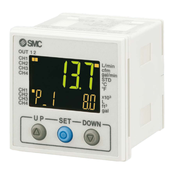
Summary of Product parts ○Names of individual parts Operation light (Orange): Lit when OUT is ON. Main display (Red/Green): Displays the current status of flow, setting mode, selected indication unit and error code. UP button: Selects the channel and mode, and increases the ON/OFF set value. DOWN button: Changes the sub display, selects the mode and decreases the ON/OFF set value. - Page 11 ●IO-Link indicator light operation and display IO-Link status Communication 1 indicator light Status Sub screen display Content with master Normal communication status Operate (Reading of measurement value) Correct Start up When communication starts up. Preoperate Version does not Version of master and IO-Link 2 match...
-
Page 12: Definition And Terminology
■Definition and terminology Term Definition The total amount of fluid that has passed through the device. If an Accumulated flow instantaneous flow of 100 L/min continues for 5 minutes, the accumulated flow will be 5 x 100 = 500 L. A type of output where a pulse is generated every time a predefined Accumulated pulse output accumulated flow passes. - Page 13 Term Definition A mode in which setting of functions is performed. If any function settings need to be changed from the factory default, each setting can be selected Function selection mode with "F". The setting items are: output mode, output type, display colour, digital filter, reverse display, zero-cut off display or no display, display value fine adjustment, use of power saving mode, security code, etc.
- Page 14 Term Definition Shows the maximum value from when the power was supplied to the current Peak value display (mode) time. Operating mode in which the digital display turns off and power consumption Power saving mode is reduced. Indicates the change in the display value and analogue output when fluid Pressure characteristics pressure changes.
-
Page 15: Mounting And Installation
Mounting and Installation ■Installation ○Mounting by panel mount adapter ●Fix the panel mount adapter to the Controller with the set screws M3 x 8L (2 pcs.) as attached. •Panel mount adapter (Model: ZS-26-B) Panel mount adapter + Front protective cover (Model: ZS-26-01) : The panel mount adapter can be rotated by 90 degrees for mounting. - Page 16 Notice when removing to the controller ●The Monitor with the panel mount adapter can be removed from facility after removing two screws as shown in a figure, by making insert the suitable thin card for the hook of both the sides, pull a panel mount adapter to the front, and remove it. If panel mount adapter is drawn forward with hook caught, the adapter and Monitor may be damaged.
-
Page 17: Wiring
■Wiring ○Wiring connections ●Connections should be made with the power supply turned off. ●Use a separate route for the product wiring and any power or high voltage wiring. Otherwise, malfunction may result due to noise. ●If a commercially available switching power supply is used, be sure to ground the frame ground (FG) terminal. - Page 18 ○Connector Connecting/Disconnecting ●When connecting the connector, insert it straight onto the pin and lock the connector into the square groove in the housing until connector clicks. ●When removing the connector, press down the lever with your thumb and pull the connector straight out. Pin No.
-
Page 19: Internal Circuit And Wiring Example
■Internal circuit and wiring example ○Output specification When the lead wire with SMC power and output lead wire (Model: ZS-26-L) is used, the colours of wire (Brown, Blue, White, Gray, Red, Green Yellow) will apply as shown on circuit diagram. PFG200-# •NPN open collector 5 output + External input Max. - Page 20 PFG202-# •IO-Link/NPN open collector 1 output + NPN open collector 4 output specification •When used as an IO-Link device Max. applied voltage: 30 V, Load current 80 mA Internal voltage drop: 1.5 V or less •When used as a switch output device Max.
- Page 21 PFG203-# •IO-Link/PNP open collector 1 output + PNP open collector 4 output specification •Used as IO-Link device Load current 80 mA Internal voltage drop: 1.5 V or less •When used as a switch output device Load current 80 mA Internal voltage drop: 1.5 V or less -20- No.PF※※-OMA1011...
-
Page 22: Outline Of Settings
Outline of Settings Power is supplied The product code is displayed for approximately 3 sec. after supplying power. After that, measurement mode is displayed. [Initial Setting] (Function selection mode [F 0]) (Refer to page 22) Set the f range, and display unit of the connected sensor. [Measurement mode] Detects the flow after power is supplied, and indicates the display and switch operating status. -
Page 23: Initial Setting
Initial Setting ■[F 0] Connection product, flow range, display unit, enable/disable IO-Link Set the connection sensor, flow range, and display unit. Measurement mode Press the UP button to select the channel. Press the SET button between 3 and 5 sec. Displays the [F 0] Connection product, flow range, display unit, and enable/disable IO-Link. - Page 24 Setting of flow range Select the flow range suitable for the sensor to connect. : This item will not be displayed when [tEMP] is selected in the setting of the connection sensor. Item Display Content Setting of connection product [4L] 4 L range [16L] 16 L range...
- Page 25 Setting of display unit Select the unit to display the flow rate (temperature). : This item cannot be changed with products that have no unit selection function (fixed to SI unit). Item Display Content Setting of connection product L/min, L [PFW] or [Flow] is selected [PFd] is selected [GAL]...
- Page 26 [USEr] is selected in the setting of [F 0] connection product Setting of minimum unit of additional range Set the display/setting minimum unit of the flow rate (temperature). Item Display Content [0.001] 0.001 increments [0.002] 0.002 increments [0.01] 0.01 increments [0.02] 0.02 increments [Udot]...
- Page 27 Setting of display unit Select the unit to display the flow rate (temperature). : [Ft], [GAL], and [F] cannot be selected with products that have no unit selection function (fixed to SI unit). Item Display Content L/min, L [Ft] Cfm, ft [GAL] gal/min, gal [Unit]...
- Page 28 Setting of enable/disable IO-Link Select to enable or disable IO-Link. When not using IO-Link, disable this item to prevent moving to IO-Link mode by error due to noise or other unexpected input. Item Display Content [on] IO-Link enabled [ioL] Selection of enable/disable IO-Link [oFF] IO-Link disabled Press the SET button to set.
- Page 29 ●Settable range of the additional range <Minimum settable unit [Udot]: "0.001", "0.01", "0.1", "1"> <Minimum settable unit [Udot]: "0.002", "0.02", "0.2", "2"> : When flow range, minimum unit/lower limit/upper limit of additional range is changed, setting below will be initialized and cleared. These items must be set again.
-
Page 30: Step Setting Mode
3 Step Setting Mode 3 step setting mode In this mode, the set values can be input in just 3 steps. Use this mode if the product is to be used straight away, after changing only the set values. (The current flow value is displayed on the main display.) <Operation>... - Page 31 The product turns on within a set flow range (OUT1: from P1L to P1H, OUT2: from P2L to P2H) during window comparator mode. Set P1L/P2L, the lower limit of the switch operation, and P1H/P2H, the upper limit of the switch operation and WH1/WH2 (hysteresis) following the instructions given on page 29. (When reversed output is selected, the sub display (left) shows [n1L]/[n2L] and [n1H]/[n2H].) Please refer to the "List of output modes"...
-
Page 32: Simple Setting Mode
Simple Setting Mode <Operation> [Simple setting mode (hysteresis mode) In the simple setting mode, the set value, hysteresis and delay time can be changed while checking the current flow value (main display). (1) After selecting the channel, press the SET button for 1 second or longer, but less than 3 seconds, in measurement mode. -
Page 33: Function Selection Mode
Function Selection Mode ■Function selection mode After selecting the channel, in measurement mode, press the S button for 3 seconds or longer (but less than 5 seconds), to display [F 0]. Select to display the function to be changed [F□□]. Press and hold the SET button for 2 seconds or longer in function selection mode to return to measurement mode. - Page 34 ●[F 2] Setting of OUT2 Page Item Explanation Default setting Either hysteresis mode, window comparator mode, accumulated Output mode output, accumulated pulse, error output or switch output off can Hysteresis mode be selected. Reversed output Selects which type of switch output is used, normal or reversed. Normal output Flow setting Sets the ON and OFF point of the switch output.
- Page 35 ■[F 1] Setting of OUT1 Set the output mode of OUT1. Output turns on when the flow is greater than the set value. Output ON lights in green and output OFF lights in red as default setting. Please refer to the "List of output modes" on page for the relationship between the set items and operation.
- Page 36 Hysteresis setting Set the hysteresis referring to the setting method on page 29. Hysteresis mode: [H_1] Window comparator mode: [WH1] The snap shot function can be used. (Refer to page 66) Press the SET button to set. Move on to the delay time setting. Delay time setting Set the delay time referring to the setting method on...
- Page 37 ([AC] Accumulated output is selected) Accumulated output setting Press the UP or DOWN button to select accumulated output. Press the SET button to set. Move on to the accumulated value setting. Accumulated value setting Perform the accumulated value setting. (Refer to page 37) Press the SET button to set.
- Page 38 The sub screen displays the value, and the leftmost digit of the set value will start flashing. (The required accumulated value should be input one digit at a time). Press the UP or DOWN buttons to change the value. Press the SET button to move on to the input of the next right digit. Pressing the SET button again will select the next digit to the right.
- Page 39 ●List of output modes Select the operation required from the table below. Characters in ( ) are for OUT2. Normal output Reversed output Hysteresis mode Window comparator mode Accumulated output mode (Increment) Accumulated output mode (Decrement) Accumulated pulse output mode Error output mode OFF mode...
-
Page 40: F 2 Setting Of Out2
■[F 2] Setting of OUT2 Set the output mode of OUT2. Output turns on when the flow is greater than the set value. Please refer to the "List of output modes" on page for the relationship between the set items and operation. <Operation>... - Page 41 Hysteresis setting Set the hysteresis referring to the setting method on page 29. Hysteresis mode: [H_1] Window comparator mode: [WH1] The snap shot function can be used. (Refer to page 66) Press the SET button to set. Move on to the delay time setting. Delay time setting Set the delay time referring to the setting method on...
- Page 42 ([AC] Accumulated output is selected) Accumulated output setting Press the UP or DOWN button to select accumulated output. Press the SET button to set. Move on to the accumulated value setting. Accumulated value setting Perform the accumulated value setting. (Refer to page 37) Press the SET button to set.
-
Page 43: F 3 Digital Filter Setting
■[F 3] Digital filter setting The Digital filter can be selected to filter the flow measurement. Output chattering or flicker in the measurement mode display can be reduced by setting the digital filter. <Operation> Press the UP or DOWN button in function selection mode to display [F 3]. Press the SET button. -
Page 44: F10 Sub Display Setting
■[F10] Sub display setting Change the display style of the sub display. Detailed contents are shown in the pages from 44. <Operation> Press the UP or DOWN button in function selection mode to display [F10]. Press the SET button. Move on to the sub display setting. Sub display setting Press the UP or DOWN button to select the display style for the sub display. - Page 45 <Sub display> •Standard The Standard display function displays the items and values on the sub display. The displayed item varies depending on the setting of the output mode. Select the displayed items by pressing the DOWN button in measurement mode. (Hysteresis mode, error output, Accumulated output, Accumulated pulse output, switch output off) (Window comparator mode) -44-...
- Page 46 •2 value display The 2 value display function displays the items listed below on the right and left side of the sub display. List of items for selection Sub display Item Details Remarks Left side Right side When hysteresis mode is ○...
- Page 47 Table showing the output mode and output form when Md1 and Md2 are selected. Output mode Output style Display style Normal output Hysteresis mode Reversed output Normal output Window comparator mode Reversed output Accumulated output mode Normal/Reversed output Accumulated pulse output Normal/Reversed output mode Error output...
- Page 48 •Character string display •Function to display the specified character string on the sub-screen. When line name is input, characters which can be displayed for each digit are as follows. (Display pattern for 3rd, 4th, 5th, 8th and 9th digit from the left) Characters Q, X, Z, /, or ...
-
Page 49: F14 Zero Cut-Off Setting
■[F14] Zero cut-off setting When the flow display value is close to zero, the product rounds the value and zero will be displayed. The zero cut-off range is 0.0 to 10.0% F.S., and can be set in 1.0% F.S. increments. : It can be set only when [PFA] is selected as the connection product. -
Page 50: F20 External Input Setting
■[F20] External input setting This function is available when the model includes the external input function. The accumulated flow, peak value and bottom value can be reset remotely. : When using a model without external input function, this setting is not available and [---] will be displayed. •Accumulated flow external reset: A function to reset the accumulated flow value when an external input signal is applied. -
Page 51: F30 Accumulated Flow Value Hold Setting
■[F30] Accumulated flow value hold setting Select the setting in which the accumulated flow measurement value is stored to the internal memory. The default setting is not to store the accumulated flow when the power supply is turned off. This function enables the accumulated flow value to be stored in permanent memory every 5 minutes. The internal memory life varies depending on the number of times that the memory device can be accessed, so this must be taken into account before use. -
Page 52: F80 Power Saving Mode
■[F80] Power saving mode Power saving mode can be selected. When selected and no buttons are pressed for 30 seconds, the product will shift to power saving mode. <Operation> Press the UP or DOWN button in function selection mode to display [F80]. Press the SET button. -
Page 53: F81 Security Code
■[F81] Security code The security code can be turned on or off and the security code can be changed when unlocked. <Operation> Press the UP or DOWN button in function selection mode to display [F81]. Press the SET button. Move on to the security code. Security code (Setting common for all channels) Press the UP or DOWN button to select the setting of security code. - Page 54 Security code changing Press the UP or DOWN button to input the changed security code on the main display. For instructions on how to enter the security code, refer to "How to input and change the security code" on page 69. After entry, the changed security code will flash by pressing the SET button for 1 second.
-
Page 55: F90 Setting Of All Functions
●Special function setting ■[F90] Setting of all functions All functions can be set in turn. <Operation> Press the UP or DOWN button in function selection mode to display [F90]. Press the SET button. Move on to the setting of all functions. Setting of all functions Press the UP or DOWN button to select all functions. - Page 56 ●Setting of each function Order Function Setting of connection product Setting of connection sensor Setting of flow range (PFW is selected) Setting of display unit Setting of unit specification Setting of enable/disable IO-Link Output mode setting of OUT1 Reversed output setting of OUT1 Flow setting of OUT1 Hysteresis setting of OUT1 Delay time setting of OUT1...
-
Page 57: F95 Channel To Channel Copy Function Setting
■[F95] Channel to channel copy function setting Set channel to channel copy function. <Operation> Press the UP or DOWN button in function selection mode to display [F95]. Press the SET button. Move on to the channel to channel copy function setting. Channel to channel copy function setting Set values between [F 0] and [F80] are copied to the other channel. -
Page 58: F96 Sensor Input Display
■[F96] Sensor input display The sensor input signal (1 to 5 V) can be checked. <Operation> Press the UP or DOWN button in function selection mode to display [F96]. Press the SET button. Move on to the sensor input display. Sensor input display Select to display the sensor input by pressing the SET button. -
Page 59: F98 Output Check
■[F98] Output check It is possible to check the switch output operation and process data value. The switch output and process data value can be turned ON/OFF independently. <Operation> Press the UP or DOWN button in function selection mode to display [F98]. Press the SET button. - Page 60 OUT1 output check (CH2) Press the UP or DOWN button to select OUT1 output check. Move on to the OUT2 output Press the SET button to set. check (CH2). OUT2 output check (CH2) Press the UP or DOWN button to select OUT2 output check.
- Page 61 OUT2 output check (CH3) Press the UP or DOWN button to select OUT2 output check. : IO-Link mode can provide the communication function. Move on to the OUT1 output Press the SET button to set. check (CH4). OUT1 output check (CH4) Press the UP or DOWN button to select OUT1 output check.
- Page 62 Diagnostic output check (CH1) Press the UP or DOWN button to select diagnostic output check. : IO-Link mode can provide the communication function. : Refer to page for details of the diagnostic information. Move on to the diagnostic output Press the SET button to set. check (CH2).
- Page 63 Diagnostic output check (CH4) Press the UP or DOWN button to select diagnostic output check. : IO-Link mode can provide the communication function. : Refer to page for details of the diagnostic information. Press the SET button to set. Move on to the error diagnostic. Error diagnostic Press the UP or DOWN button to select error diagnostic.
- Page 64 Process data measurement value output check (CH2) The upper and lower limit values of the rated flow value can be output compulsively as PD measurement value (process data). Press the UP or DOWN button to select the lower or upper limit value. : IO-Link mode can provide the communication function.
- Page 65 Process data measurement value output check (CH4) The upper and lower limit values of the rated flow value can be output compulsively as PD measurement value (process data). Press the UP or DOWN button to select the lower or upper limit value. : IO-Link mode can provide the communication function.
-
Page 66: F99 Reset To Default Settings
■[F99] Reset to default settings If the product settings are uncertain, the default values can be restored. : All channels return to default condition. <Operation> Press the UP or DOWN button in function selection mode to display [F99]. Press the SET button. Move on to the reset to default settings. -
Page 67: Other Settings
Other Settings ○Channel scan function •Press the UP button for 2 seconds or longer. Channels and the measured flows will be displayed in order approximately every 2 seconds. •The function can be released by pressing the UP button again for 2 seconds or longer. : Channel scan function will remain even when the power supply is turned off. - Page 68 ○Key-lock function The key-lock function is used to prevent errors occurring due to unintentional changes of the set values. If the SET button is pressed while the keys are locked, [LoC] is displayed on the sub display (left) for approximately 1 second. (Each setting and peak/bottom values are displayed with UP and DOWN buttons.) <Operation - Without security code input ->...
- Page 69 <Operation – With security code input -> •Locking (1) Press the SET button for 5 seconds or longer in measurement mode. When [oPE] is displayed on the main display, release the button. The current setting [LoC] or [UnLoC] will be displayed on the sub display. (2) Select the key [LoC] with UP or DOWN button, and press the SET button to set.
- Page 70 ●How to input and change the security code The left most digit starts flashing. Press the UP or DOWN button to select a value. Press the SET button to make the next digit to the right flash. (If the SET button is pressed at the last digit, the first digit will start flashing.) After the setting is complete, Press and hold the SET button for 1 second or longer.
-
Page 71: Io-Link Specifications
IO-Link Specifications ■Outline of IO-Link functions ○Communication function This product can check the flow measurement value, diagnostic information and switch output status using cyclic data communication via the IO-Link system. ○Product status monitoring function This function monitors the product status via the IO-Link communication. •Detects the error status (internal hardware error). -
Page 72: Process Data
■Process data Process data is the data which is exchanged periodically between the master and device. This product process data consists of switch output status, error diagnostics and flow measurement value. (Refer to the table below.) Bit offset Item Notes CH1: OUT1 output 0: OFF 1: ON CH1: OUT2 output... - Page 73 ○Measurement and setting range Rated flow range Display/settable range Applicable Range Unit products Flow L/min 0.50 4.00 0.35 4.50 Flow gal/min 0.13 1.06 0.09 1.19 1000 1125 Flow L/min 16.0 17.0 16 L Flow gal/min 0.55 4.25 0.45 4.50 1000 1063 Flow L/min 40.0...
- Page 74 ○Conversion formula of the process data and measurement value (1) Conversion formula from the process data to the measurement value: Pr = a × (PD) + b (2) Conversion formula from the measurement value to the process data: (PD) = (Pr – b) / a Pr: Measurement value and directive value PD: Measurement value (process data) a: Inclination...
- Page 75 [Calculation example] (1) Conversion from the process data to the flow measurement value (For range: 16 L/min, unit specification L/min and PD=500) Pr = a x (PD) + b = 0.016 x 500 + 0 = 8.00 [L/min] (2) Conversion from the flow measurement value to the process data (For range: 100 L/min, unit specification cfm and Pr=2.0[cfm]) (PD) = (Pr - b) / a = [2.0 - (0)]/(0.00353)
-
Page 76: Io-Link Parameter Setting
The IODD file is shown below. 1 Product No. IODD file PFG20# SMC-PFG200-yyyymmdd-IODD1.1 1: "yyyymmdd" indicates the file preparation date. yyyy is the year, mm is the month and dd is the date. The IODD file can be downloaded from the SMC Web site (https://www.smcworld.com). - Page 77 ●ISDU parameters Index 1 Parameters Initial value Remarks Access index (dec) 0x0002 Refer to "System command" on System command ― page 77. 0x000C Refer to "Device access lock 2 Device access lock 0x0000 (12) parameter" on page 78. 0x0010 Vendor name SMC Corporation (16) 0x0011...
- Page 78 ●System command (index 2) In the ISDU index 0x0002 SystemCommand (system command), the command shown in the table below will be issued. The button of each system command is displayed on the IO-Link setting tool (excluding "ParamDownloadStore"). Click the button to send the system command to the product. Writable commands are shown below.
- Page 79 ●Device access lock parameter (index 12) The contents are as follows. Data type: 16 bit Record Value (dec) Contents 0x0000 (0) Key lock release, DS unlock (Initial value) 0x0002 (2) Key lock release, DS lock 0x0008 (8) Key lock, DS unlock 0x000A (10) Key lock, DS lock [Key lock]...
- Page 80 ●Device detail status parameters (index 37) Detailed event contents of readable device status are as follows. Event classification Array Event content Event code Definition Value 0xF4 0x8D03 Internal product malfunction Error 0xF4 0x8D04 Internal product malfunction Error 0xF4 0x8D05 Internal product malfunction Error Internal product malfunction 0xF4...
- Page 81 ●Product individual parameters Index Data Data Initial value Access (dec) Sub index Parameter Remarks 2 3 1 storage type (dec) Setting of display colour. 0: rEd (Constantly red) 1: Grn (Constantly green) 0x03F2 0x03F3 0x03F4 0x03F5 0x02 2: 1SoG (OUT1 turns green at ON) (Selection of display (1010)
- Page 82 ●Product individual parameters (continued) Index Data Data Initial value Access (dec) Sub index Parameter Remarks 2 3 1 storage type (dec) Set the channel to be displayed. 0: CH1 0x00 Channel select 1: CH2 2: CH3 0x041A 3: CH4 (1050) Set the channel scan mode.
- Page 83 ●Product individual parameters (continued) Index Data Data Initial value Access (dec) Sub index Parameter Remarks 2 3 1 storage type (dec) Setting of the flow rate output mode. 0: HYS (Hysteresis) oUt2 (Selection of OUT2 0x00 1: Wind (Window comparator) 2: AC (Accumulated) output operation 3: PLS (Accumulated pulse)
- Page 84 ●Product individual parameters (continued) Index Data Data Initial value Access (dec) Sub index Parameter Remarks 2 3 1 storage type (dec) Set the accumulated direction. 0x0640 0x0641 0x0642 0x0643 0x0000 0: Add (Addition) (Accumulated (1600) (1601) (1602) (1603) 1: dEC (Subtraction OUT1) display direction)
- Page 85 ●Product individual parameters (continued) Index Data Data Initial value Access (dec) Sub index Parameter Remarks 2 3 1 storage type (dec) 0x00 Line name Refer to Figure "Line name 1st letter (11 SEG) communication data (11 seg)". Line name 0x00 Refer to Figure "Line name...
- Page 86 ●Product individual parameters (continued) Index Data Data Initial value Access (dec) Sub index Parameter Remarks 2 3 1 storage type (dec) When a fixed output is received: test 0x1B58 0x00 Set the bit in PD to 1. (Output signal (7000) 0: Normal output...
- Page 87 [Selection of display items during dEF setting] Value Setting content Supplemental information HYS mode set value HYS mode hysteresis Wind mode lower side set value Wind mode upper side set value OUT1 Wind mode hysteresis AC mode set value PLS mode Err mode When the value which does not match the OUT...
- Page 88 [2 value display communication data] Selection of display items during Value Setting content Supplemental information 2 value setting Left side Right side ● ● HYS mode set value ● ● HYS mode hysteresis ● ● OUT1 Wind mode lower side set value ●...
- Page 89 [Line name communication data] Value (16 Hex number) 7seg Display letter 11seg Value (16 Hex number) 7seg Display letter 11seg Value (16 Hex number) 7seg Display letter 11seg Supplementary : Do not work information [Toggle output command] Value Item Remarks Measurement value CH1_OUT1 CH1_OUT2...
-
Page 90: Maintenance
Maintenance How to reset the product after a power cut or forcible de-energizing The setting of the product will be retained as it was before a power cut or de-energizing. The output condition is also basically recovered to that before a power cut or de-energizing, but may change depending on the operating environment. -
Page 91: Troubleshooting
Troubleshooting ○Troubleshooting When any failure occurs with this product, the following chart can be used to identify the cause of the failure. If a cause applicable to the troubles cannot be identified and normal operation is recovered by replacement with a new product, this indicates that the product itself was faulty. Problems with the product may be due to the operating environment (installation etc). - Page 92 The display is Refer to Trouble No.7 Displayed value is not unstable. correct Refer to Trouble No.9 The display turns OFF. Refer to Trouble No.9 The display is missing. Refer to Trouble No.10 Display flashes. The display accuracy Refer to Trouble No.11 does not meet the specifications.
- Page 93 ○Troubleshooting list Problem Problem possible Problem Investigation method Countermeasures causes •The switch (1) Check the set flow value. output does not (2) Check the settings of the turn OFF. (1) Adjust the set flow value. operation mode, hysteresis and The operation Incorrect flow (2) Set the operation mode, output type.
- Page 94 Problem Problem possible Problem Investigation method Countermeasures causes (1) Check the set flow value. (1) Adjust the set flow value. The switch Incorrect flow (2) Check if the hysteresis range is large. (2) Make the hysteresis output response setting (3) Check the delay time setting. narrower.
- Page 95 Problem Problem possible Problem Investigation method Countermeasures causes Check the setting of connection Incorrect setting product. of connection Select the correct product. Check that the connected product Applied flow does product and the set product are correct. not match with the displayed value.
- Page 96 Problem Problem possible Problem Investigation method Countermeasures causes Unit s selection function is not available for fixed to SI Model selection units type. (model selected Check if the product number printed Display (kPaMPa is available) does not have on the product indicates units measurement : The units selection function is units selection...
- Page 97 ○Troubleshooting (IO-Link communication function) IO-Link indicator light The IO-Link function Refer to Trouble No.1 : OFF is OFF. IO-Link indicator light Refer to Trouble No.2 : Flashing IO-Link indicator light : ON Input and output are Refer to Trouble No.3 swapped by byte.
- Page 98 ○Troubleshooting list (IO-Link communication) Problem Problem Problem Investigation method Countermeasures possible causes Description Check the connection of incorrect wiring Correct the cable wiring. the connector. IO-Link indicator ― light Power supply Check the power supply Supply 18 to 30 VDC to : OFF error from the voltage from the IO-Link...
- Page 99 ○IO-Link status list Sub display indication Details Data storage uploading Data storage downloading Block parameter uploading Block parameter downloading Receiving restore Factory Setting Receiving Peak Bottom Clear Receiving Accumulate reset Receiving Application Reset : When the operation is completed, the display will return to normal. -98- No.PF※※-OMA1011...
- Page 100 ○Error indication function This function is to display error location and content when a problem or error has occurred. Error Error displayed Description Measures Error output Turn the power off and 2 The switch output load current is 80 remove the cause of Over current ○...
- Page 101 Setting of the error output In reversed output mode, error [Er0], [Er4] and [Er40] can be detected. Normal output Reversed output -100- No.PF※※-OMA1011...
-
Page 102: Specifications
Specifications Model PFG20# series PF2A5 PF3W5 PF2D5 Applicable flow sensor 1 to 10 5 to 50 10 to 100 20 to 200 50 to 500 0.5 to 4 2 to 16 5 to 40 10 to 100 50 to 250 0.4 to 4... - Page 103 Model PFG20# series PF2A5 PF3W5 PF2D5 Applicable flow sensor Output type NPN or PNP open collector output5 output Output mode Hysteresis, window comparator, accumulated output, accumulated pulse output, error output, output OFF Switch operation Normal output, reversed output Maximum load current...
- Page 104 ○Cable specification Conductor area 0.15 mm (AWG26) Insulator Outside diameter 0.9 mm ϕ 4.8 Sheath Finished outside diameter ○Communication specification (During IO-Link mode) IO-Link type Device IO-Link version V1.1 Communication speed COM2 (38.4 kbps) 8 Configuration file IODD file Min. cycle time 4.8 ms Process data length Input Data: 10 byte, Output Data: 0 byte...
-
Page 105: Dimensions
■Dimensions ○Power supply/output cable •ZS-26-L -104- No.PF※※-OMA1011... - Page 106 Revision history 4-14-1, Sotokanda, Chiyoda-ku, Tokyo 101-0021 JAPAN Tel: + 81 3 5207 8249 Fax: +81 3 5298 5362 https://www.smcworld.com Note: Specifications are subject to change without prior notice and any obligation on the part of the manufacturer. © 2023 SMC Corporation All Rights Reserved No.PF※※-OMA1011...
Need help?
Do you have a question about the PFG20 and is the answer not in the manual?
Questions and answers