
Related Manuals for SMC Networks PFG3 0 Series


Summary of Contents for SMC Networks PFG3 0 Series
- Page 1 No.PF※※-OMU0007-B PRODUCT NAME Digital Flow Monitor MODEL / Series / Product Number PFG3#0...
-
Page 2: Table Of Contents
Table of Contents Safety Instructions Model Indication and How to Order Summary of Product parts Definition and terminology Mounting and Installation Installation Wiring Flow Setting Outline of Settings Initial Setting 3 Step Setting Mode Simple Setting Mode Function Selection Mode Function selection mode Default setting F0 Flow range, display units and switch output selection... -
Page 3: Safety Instructions
Safety Instructions These safety instructions are intended to prevent hazardous situations and/or equipment damage. These instructions indicate the level of potential hazard with the labels of "Caution", "Warning" or "Danger". They are all important notes for safety and must be followed in addition to International Standards (ISO/IEC) , and other safety regulations. - Page 4 Safety Instructions Caution 1.The product is provided for use in manufacturing industries. The product herein described is basically provided for peaceful use in manufacturing industries. If considering using the product in other industries, consult SMC beforehand and exchange specifications or a contract if necessary. If anything is unclear, contact your nearest sales branch.
- Page 5 Operator This operation manual is intended for those who have knowledge of machinery using pneumatic equipment, and have sufficient knowledge of assembly, operation and maintenance of such equipment. Only those persons are allowed to perform assembly, operation and maintenance. Read and understand this operation manual carefully before assembling, operating or providing maintenance to the product.
- Page 6 Caution ■Do not touch the terminals and connectors while the power is on. Otherwise electric shock, malfunction or damage to the product can result. ■After maintenance is complete, perform appropriate functional inspections and leak tests. Stop operation if the equipment does not function properly or there is a leakage of fluid. When leakage occurs from parts other than the piping, the product might be faulty.
- Page 7 ●Product handling Installation Tighten to the specified tightening torque. If the tightening torque is exceeded the mounting screws and brackets may be broken. If the tightening torque is insufficient, the product can be displaced and loosen the mounting screws. Be sure to ground terminal FG when using a commercially available switch-mode power supply. Do not drop, hit or apply shock to the product.
- Page 8 Do not use a load which generates surge voltage. When a surge-generating load such as a relay or solenoid is driven directly, use a product with a built-in surge absorbing element. The product is CE marked, but not immune to lightning strikes. Take measures against lightning strikes in the system.
-
Page 9: Model Indication And How To Order
Model Indication and How to Order ○Accessories/Part numbers If an option is required independently, order with the following part numbers. Items Part No. Remarks Sensor connector (For PFMB) ZS-28-C-1 Sensor connector (For PFMC and PF3A7) ZS-28-CA-4 Bracket A ZS-46-A1 Self tapping screws: Nominal size 3 x 8L (2 pcs) Bracket B ZS-46-A2 Self tapping screws: Nominal size 3 x 8L (2 pcs) -
Page 10: Summary Of Product Parts
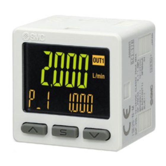
Summary of Product parts ○Names of individual parts Operation light: Displays the switch operating condition. LCD display: Displays the current status of flow, setting mode, selected display units and error code. 4 types of display can be selected for the main display: Single colour of constant red or green; or switching from red to green or green to red corresponding to the output. -
Page 11: Definition And Terminology
■Definition and terminology Term Definition The total amount of fluid that has passed through the device. If an instantaneous flow Accumulated flow of 1,000 L/min lasts for 5 minutes, the accumulated flow will be 5 x 1,000 = 5,000 L. A type of output where a pulse is generated every time a predefined accumulated flow Accumulated pulse output passes. - Page 12 Term Definition The mode in which setting of functions is performed. It is a separate menu from the display setting. If any function settings need to be changed from the factory default, each setting can be selected with “F*”. The setting items are: display Function selection mode colour, display range, display units, operation mode, output type, delay time, digital filter, power saving mode, security code, etc.
-
Page 13: Mounting And Installation
Mounting and Installation ■Installation ○Mounting with bracket ●Mount the bracket to the body with mounting screws (Self tapping screws: Nominal size 3 x 8L (2 pcs)), then set the body to the specified position. : Tighten the bracket mounting screws to a torque of 0.5±0.05 Nm. Self tapping screws are used, and should not be re-used several times. - Page 14 ○Mounting with panel mount adapter ●Mount part (a) to the front of the body and fix it. Then insert the body with (a) into the panel until (a) comes into contact with the panel front surface. Next, mount part (b) to the body from the rear and insert it until (b) comes into contact with the panel for fixing.
-
Page 15: Wiring
■Wiring ○Wiring connections ●Connections should be made with the power supply turned off. ●Use a separate route for the product wiring and any power or high voltage wiring. Otherwise, malfunction may result due to noise. ●If a commercially available switching power supply is used, be sure to ground the frame ground (FG) terminal. - Page 16 Attaching the connector to the sensor wire •Strip the sensor wire as shown. •Do not cut the insulator. •Insert the corresponding wire colour shown in the table into the pin number printed on the sensor connector, to the bottom. Pin no.
- Page 17 ○Internal circuit and wiring examples PFG3□0-□-□-□□□□ Output specification -RT/-SV •NPN open collector 2 output + Analogue output Max.30 V, 80 mA Residual voltage: 1 V or less RT: Analogue output 1 to 5 V, 0 to 10 V Output impedance 1 kΩ SV: Analogue output 4 to 20 mA Max.
- Page 18 -RT/SV/XY •NPN open collector 2 output + Copy function Max. 30 V, 80 mA Residual voltage: 1 V or less -RT/-SV •PNP open collector 2 output + Analogue output Max. 80 mA Residual voltage: 1.5 V or less RT: Analogue output 1 to 5 V, 0 to 10 V Output impedance 1 kΩ...
- Page 19 -RT/-SV •PNP open collector 2 output + External input Max. 80 mA Residual voltage: 1.5 V or less External input: Input voltage 0.4 V or less (reed or solid state), 30 msec or more -RT/SV/XY •PNP open collector 2 output + Copy function Max.30 V, 80 mA Residual voltage: 1.5 V or less -18-...
- Page 20 Example for wiring for accumulated pulse output NPN open collector 2 output PNP open collector 2 output -19- No.PF※※-OMU0007-B...
-
Page 21: Flow Setting
Flow Setting Default settings When the flow exceeds the set value, the switch will be turned on. When the flow falls below the set value by the amount of hysteresis or more, the switch will be turned off. The default setting is that the output will be turned ON at 1500 L/min when the flow range of the connected sensor is 3000 L/min. -
Page 22: Outline Of Settings
Outline of Settings Power is supplied. The product code is displayed for approximately 3 sec. after power is supplied. Then, measurement mode will be displayed. : When moving on to measurement mode, the switch operation will start. [Initial setting] (Refer to page 22.) Set the flow range, display unit and NPN/PNP output specifications of the connected sensor. -
Page 23: Initial Setting
Initial Setting Set the flow range, display unit and NPN/PNP output specifications of the connected sensor. Measurement mode Press the button between 3 and 5 sec. [F 0] Display the switching function of the flow range, display unit and switch output specifications. Press the button Move on to flow range setting. - Page 24 Setting of the lower limit of the additional rated range When the products with a Press the button to change the value. units selection Press the button continuously to keep changing the value. Set the value that is required to be displayed when the sensor input signal is 0%.
- Page 25 Press the button to set. Move on to display unit setting. Display unit setting Press the button to change the display units. : [CFM] cannot be selected if the additional range is set by the SI unit. : [w/o unit] cannot be selected if set items other than additional range are set with the units selection function. Move on to switching setting of switch output Press the button to set.
- Page 26 Flow specification when [Ft] is selected by the units selection function Model PFG3#0 PFMB7501 PFMB7102 PFMB7202 Model PFMB7201 PF3A703H PF3A706H PF3A712H Applicable PFMC7501 PFMC7102 PFMC7202 SMC Flow 0.08 to 0.2 to 0.4 to 0.8 to 1.1 to 2.2 to 4.5 to Switch Rated flow range 7.06 cfm...
-
Page 27: Step Setting Mode
3 Step Setting Mode 3 step setting mode In this mode, the set values can be input in just 3 steps. Use this mode if the product is to be used straight away, after changing only the set values. (The current flow value is displayed on the main display.) <Operation>... - Page 28 The Flow switch turns on within a set flow range (OUT1: from P1L to P1H, OUT2: from P2L to P2H) during window comparator mode. Set P1L/P2L, the lower limit of the switch operation, and P1H/P2H, the upper limit of the switch operation and WH1/WH2 (hysteresis) following the instructions given on page 26. (When reversed output is selected, the sub display (left) shows [n1L/n2L] and [n1H/n2H].) In accumulated output mode, the switch will start at the set accumulated flow rate.
-
Page 29: Simple Setting Mode
Simple Setting Mode <Operation> [Simple setting mode (hysteresis mode) In the simple setting mode, the set value and hysteresis can be changed while checking the current flow value (main display). (1) Press and hold the button between 1 and 3 seconds in measurement mode. [SEt] is displayed on the main display. -
Page 30: Function Selection Mode
Function Selection Mode ■Function selection mode In measurement mode, press the button between 3 and 5 seconds, to display [F 0]. Select to display the function to be changed [F□□]. Press and hold the button for 2 seconds or longer in function selection mode to return to measurement mode. - Page 31 ●[F 2] Setting of OUT2 Page Item Explanation Default setting Either hysteresis mode, window comparator mode, accumulated Output mode output, accumulated pulse, error output or switch output off can Hysteresis mode be selected. Reversed output Selects which type of switch output is used, normal or reversed. Normal output Flow setting Sets the ON and OFF point of the switch output.
-
Page 32: F0 Flow Range, Display Units And Switch Output Selection
■[F 0] Flow range, display units and switch output specification Flow range setting A Flow range which is suitable for the connected sensor can be selected. In addition, the required range can be set and displayed. (Custom range) ●Relationship between analogue input and digital display Set value 200 L/min 0 L/min... - Page 33 <Operation> Press the button in function selection mode to display [F 0]. Press the button. Move on to flow range setting. Flow range setting Press the button to select the flow range. When [USEr] is selected Press the button to move on to additional range minimum unit setting.
- Page 34 Setting of the lower limit of the additional rated range When the products with a Press the button to change the value. units selection Press the button continuously to keep changing the value. Set the value that is required to be displayed when the sensor input signal is 0%.
- Page 35 Press the button to set. Move on to display unit setting. Display unit setting Press the button to change the display units. : [CFM] cannot be selected if the additional range is set by the SI unit. : [w/o unit] cannot be selected if set items other than additional range are set with the units selection function. Move on to switching setting of switch output Press the button to set.
-
Page 36: F 1 Setting Of Out1
■[F 1] Setting of OUT1 Set the output mode of OUT1. The output signal turns ON when the flow is greater than the set value. When the output is ON the LED is green and when the output is OFF the LED is red as the default setting. Refer to the "List of output modes"... - Page 37 Hysteresis setting Set the flow referring to the setting method on page 26. Hysteresis mode: [H_1] Window comparator mode: [WH1] The snap shot function can also be used. (Refer to page 64.) Press the button to set. Move on to delay time setting. Delay time setting The delay time of the switch output can be set by pressing the...
- Page 38 ([AC] When accumulated output is selected) Accumulated output setting Press the button to select accumulated output. Press the button to set. Move on to accumulated value setting. Accumulated value setting Perform the accumulated value setting (Refer to page 38.) Press the button to set.
- Page 39 Setting of the first 6 Setting of the next 6 The sub screen displays the digits digits value, and the leftmost digit of the set value will start flashing. Press the (The required accumulated value button should be input one digit at a again.
- Page 40 ●List of output modes Select the operation required from the table below. Characters in ( ) are for OUT2. Normal output Reversed output Hysteresis mode Window comparator mode Accumulated output mode (Increment) Accumulated output mode (Decrement) Accumulated pulse output mode Error output mode OFF mode...
-
Page 41: F 2 Setting Of Out2
■[F 2] Setting of OUT2 Set the output mode of OUT2. The output signal turns ON when the flow is greater than the set value. Refer to the "List of output modes" on page for the relationship between the set items and the operation. <Operation>... - Page 42 Hysteresis setting Set the flow referring to the setting method on page 26. Hysteresis mode: [H_2] Window comparator mode: [WH2] The snap shot function can also be used. (Refer to page 64.) Press the button to set. Move on to delay time setting. Delay time setting The delay time of the switch output can be set by pressing the...
- Page 43 ([AC] When accumulated output is selected) Accumulated output setting Press the button to select accumulated output. Press the button to set. Move on to accumulated value setting. Accumulated value setting Perform the accumulated value setting (Refer to page 38.) Press the button to set.
-
Page 44: F 3 Digital Filter Setting
■[F 3] Digital filter setting The digital filter can be selected to filter the flow measurement (0 to 30 sec.). Output chattering or display flicker in measurement mode can be reduced by setting the digital filter. <Operation> Press the button in function selection mode to display [F 3]. Press the button. -
Page 45: F5 Func Terminal Function Setting
■[F 5] FUNC terminal function setting Analogue output, external input or copy function can be selected. : Do not connect the grey wire when changing the setting. •When the analogue output is selected When the product with analogue voltage output is used, the output of 1 to 5 V or 0 to 10 V can be selected. A flow value corresponding to 5 V (10 V) or 20 mA can be selected with the analogue output free range function. - Page 46 <Operation> Press the button in function selection mode to display [F 5]. Press the button. Moves on to FUNC terminal function setting. FUNC terminal function setting Press the button to select the required function. Analogue voltage output External input [in] [oUt] (Analogue output) Press the button to move...
- Page 47 Free range setting Press the button to select the free range setting. [oFF] not used [on] is enabled Press the button to set. Press the button to move on to set value. Return to function selection mode. Set value Use the buttons to enter the flow value to correspond with the full span analogue output (5 V or 10 V or 20 mA).
-
Page 48: F10 Sub Display Setting
■[F10] Sub display setting Change the display style of the sub display. •Initial setting (standard): Accumulated value, set value for OUT, peak value, or bottom value is displayed. •Addition of line name: A line name can be added to the default display. A line name can be entered comprising of up to 5 characters and/or numbers. - Page 49 •Characters which can be displayed for each digit are as follows. Characters Q, X, Z,/, or cannot be displayed. <Sub display> •Standard The Standard display function displays the items and values on the sub display. The displayed item varies depending on the setting of the output mode. Select the displayed items by pressing the button in measurement mode.
-
Page 50: F14 Display With Zero Cut-Off Setting
■[F14] Display with zero cut-off setting When the flow is close to 0 L/min., the product rounds the value down and zero will be displayed. This is adjustable within the range of 10% F.S. of the flow range. <Operation> Press the button in function selection mode to display [F14]. - Page 51 ●When the set value and hysteresis of the switch output (OUT) is set within the zero-cut range. The operating point of the switch output will be changed, depending on the zero-cut setting value. However, please note that the set value and hysteresis of the switch output will not be changed. To maintain the on-off point, set the value and hysteresis without the zero cut-off range.
-
Page 52: F30 Accumulated Value Hold Setting
■[F30] Accumulated value hold setting This function enables the accumulated flow value to be stored in permanent memory every 2 or 5 minutes. In the default setting, the accumulated flow value is not held when the power supply is turned off. : When using the accumulated value hold function, calculate the product life from the operating conditions, and use the product within its life. -
Page 53: F80 Power Saving Mode
■[F80] Power saving mode Power saving mode can be selected. When selected, if no buttons are pressed for 30 seconds, the product will shift to power saving mode. <Operation> Press the button in function selection mode to display [F80]. Press the button. -
Page 54: F81 Security Code
■[F81] Security code The security code can be turned on or off and the security code can be changed when unlocked. <Operation> Press the button in function selection mode to display [F81]. Press the button. Move on to security code. Security code Press the button to select the setting of security code. - Page 55 Changing the security code Press the button to enter the changed security code on the main display. For instructions on how to enter the security code, refer to "How to input and change the security code" on page 67. After entry, the new security code will flash by pressing the button for 1 second...
-
Page 56: F90 Setting Of All Functions
■[F90] Setting of all functions All functions can be set in turn. <Operation> Press the button in function selection mode to display [F90]. Press the button. Move on to setting of all functions. Setting of all functions Press the button to select all functions. [on] (used) is selected [oFF] (not used) is ... - Page 57 ● Setting of each function Order Function Flow range setting Display unit setting Switching setting of switch output NPN/PNP specifications Output mode setting of OUT1 Reversed output setting of OUT1 Flow setting of OUT1 Hysteresis setting of OUT1 Delay time setting of OUT1 Display colour setting Output mode setting of OUT2 Reversed output setting of OUT2...
-
Page 58: F96 Sensor Input/External Input Signal Status Display
■[F96] Sensor input/External input signal status display The sensor input signal (1 to 5 V or 4 to 20 mA) and the external input signal can be checked. <Operation> Press the button in function selection mode to display [F96]. Move on to sensor input/external input signal status Press the button. -
Page 59: F97 Copy Master Setting
■[F97] Copy master setting The set values can be copied. When the input specification, output specification and the units specification are the same, this function is available. The set value can be copied to up to 10 flow monitors simultaneously. <Connection>... - Page 60 Copy starts Press the button. Copying (Auto switch) Copy completed Press the buttons simultaneously for 1 second or longer. [F97] Copy master setting completed -59- No.PF※※-OMU0007-B...
- Page 61 After selecting the copy master, all other connected monitors switch to slave mode. (Auto switch) Press the buttons simultaneously for 1 second or longer. -60- No.PF※※-OMU0007-B...
-
Page 62: F98 Output Check
■[F98] Output check The switch output or analogue output can be selected for an output check. The output can be turned ON/OFF manually for checking. <Operation> Press the button in function selection mode to display [F98]. Press the button. Move on to output check. Output check Press the button to select output check. - Page 63 OUT2 output check Press the button to select OUT2 output check. When switching of analogue output is selected for the setting of [F 5] FUNC terminal function Press the button to move on to FUNC terminal function setting. FUNC terminal When external input function setting or copy function is...
-
Page 64: F99 Reset To Default Settings
■[F99] Reset to default settings If the product settings have become uncertain, the default values can be restored. <Operation> Press the button in function selection mode to display [F99]. Press the button. Move on to reset to default settings. Reset to default settings Press the button to display [ON], then press the buttons simultaneously for 5 seconds or longer. -
Page 65: Other Settings
Other Settings ○Snap shot function The current flow value can be stored to the switch output ON/OFF set point. When the items of sub display (left) below are selected in 3 step setting mode, simple setting mode or function selection mode ([F 1] Setting of OUT1, [F 2] Setting of OUT2), by pressing the buttons simultaneously for 1 second or longer, the value of the sub display (right) shows [- - -], and the values corresponding to the current flow values are automatically displayed. - Page 66 ○Key-lock function The key-lock function is used to prevent errors occurring due to unintentional changes of the set values. If button is pressed while the keys are locked, [LoC] is displayed on the sub display (right) for approximately 1 second. (Each setting and peak/bottom values are displayed with buttons.) <Operation - Without security code input ->...
- Page 67 <Operation – With security code input -> •Locking (1) Press the button for 5 seconds or longer in measurement mode. When [oPE] is displayed on the main display, release the button. The current setting [LoC] or [UnLoC] will be displayed on the sub display. (2) Select the key [LoC] with button, and press the button to set.
- Page 68 ●How to input and change the security code The left most digit starts flashing. Press the button to select a value. Press the button to make the next digit to the right flash. (If the button is pressed at the last digit, the first digit will start flashing).
-
Page 69: Maintenance
Maintenance How to reset the product after a power cut or forcible de-energizing The setting of the product will be retained as it was before a power cut or de-energizing. The output condition is also basically recovered to that before a power cut or de-energizing, but may change depending on the operating environment. -
Page 70: Troubleshooting
Troubleshooting ○Troubleshooting When any failure occurs with this product, the following chart can be used to identify the cause of the failure. If a cause applicable to the troubles cannot be identified and normal operation is recovered by replacement with a new product, this indicates that the product itself was faulty. Problems with the product may be due to the operating environment (installation etc). - Page 71 Refer to Trouble Displayed value is not The display is unstable. No.7 correct. Refer to Trouble The display turns OFF. No.9 Refer to Trouble The display is missing. No.9 Refer to Trouble Display flashes. No.10 There are differences Refer to Trouble in the displayed values No.11 when using more than one...
- Page 72 ○Troubleshooting Problem Problem Possible cause Investigation method Countermeasures (1) Check the set flow value. • The switch (2) Check the settings of the output does not operation mode, hysteresis and turn OFF. output type. (1) Adjust the set flow value. The operation (Hysteresis mode/Window Incorrect flow...
- Page 73 Problem Problem Possible cause Investigation method Countermeasures (1) Check if the output current is 20 (1)(2) Connect the mA or more. appropriate load. (2) Check if the connected load (3) Use a relay with a surge complies with the specification. Excess current voltage suppressor or Check if the load is short circuited.
- Page 74 Problem Problem Possible cause Investigation method Countermeasures Applied voltage Check the flow range setting. does not match Incorrect flow Select the correct flow Check if the connected flow sensor with the displayed range setting range. and the set flow range are correct. pressure value.
- Page 75 Problem Problem Possible cause Investigation method Countermeasures Model selection Units selection function is (the model not available for the fixed SI Check if the product number printed Display selected does units type. on the product indicates a type with measurement : The units selection function is not have the units selection function.
- Page 76 ○Error indication function This function is to display error location and content when a problem or error has occurred. Error Error displayed Description Measures Turn the power off and remove the Over current The switch output load current is 80 mA cause of the over current.
- Page 77 Error Error displayed Description Measures Turn the power off and on again. Displayed if an internal data error has System error If the failure cannot be solved, occurred. contact SMC. If the error cannot be reset after the above measures are taken, or errors other than above are displayed, please contact SMC.
-
Page 78: Specification
Specification Model PFG3#0 PFMB7501 PFMB7102 PFMB7202 Model PFMB7201 PF3A703H PF3A706H PF3A712H Applicable PFMC7501 PFMC7102 PFMC7202 SMC Flow 2 to 5 to 10 to 20 to 30 to 60 to 120 to Switch 1 Rated flow range 200 L/min 500 L/min 1000 L/min 2000 L/min 3000 L/min... - Page 79 Model PFG3#0 External input specification Input voltage: 0.4 V or less (reed or solid state type), Input time: 30 msec. or longer External input 6 Input mode Accumulated flow external reset or peak/bottom hold value Voltage input: 1 to 5 VDC (Input impedance: 1 MΩ) Current input: 4 to 20 mA (Input impedance: 51 Ω) Input type (0 L/min to maximum value of the rated flow)
-
Page 80: Dimensions
■Dimensions -79- No.PF※※-OMU0007-B... - Page 81 ○Bracket A (Part No: ZS-46-A1) ○Bracket B (Part No: ZS-46-A2) -80- No.PF※※-OMU0007-B...
- Page 82 ○Panel mount adapter (Part No: ZS-46-B) ○Panel mount adapter + Front protective cover (Part No: ZS-46-D) -81- No.PF※※-OMU0007-B...
- Page 83 ○Lead wire with connector (Part No: ZS-46-5L) 0.15 mm (AWG26) Conductor area 1.0 mm Outside diameter Insulator Brown, Blue, Black, white, grey (5 core) Colour 3.5 Sheath Finished outside diameter ○Sensor connector (Part No: ZS-28-C-1) PIN No. Description DC(+) N.C. DC(-) ...
- Page 84 ○Panel cut-out dimensions Mounting individually More than 2 pcs. (n pcs.) Close mounting <Horizontal> <Vertical> -83- No.PF※※-OMU0007-B...
- Page 85 Revision history A: Contents are added. [October 2017] B: Contents revised in several places. [June 2018] 4-14-1, Sotokanda, Chiyoda-ku, Tokyo 101-0021 JAPAN Tel: + 81 3 5207 8249 Fax: +81 3 5298 5362 http://www.smcworld.com Note: Specifications are subject to change without prior notice and any obligation on the part of the manufacturer. ©...
Need help?
Do you have a question about the PFG3 0 Series and is the answer not in the manual?
Questions and answers