
Related Manuals for SMC Networks ISA3-G series


Summary of Contents for SMC Networks ISA3-G series
- Page 1 No.PS※※-OMR0002-G PRODUCT NAME Digital Gap Checker MODEL / Series / Product Number ISA3 series...
-
Page 2: Table Of Contents
Table of Contents 1 Before Use Safety Instructions Features Model Indication and How to Order Summary of Product parts Specification 2 About this product Specifications (ISA3) ··································· Specifications (Regulator) ····························· Specifications (2 port solenoid valve) ··············· Characteristics graph ··································· Dimensions ··············································· Mounting and Installation Piping ······················································... -
Page 3: Before Use
Before Use Safety Instructions These safety instructions are intended to prevent hazardous situations and/or equipment damage. These instructions indicate the level of potential hazard with the labels of "Caution", "Warning" or "Danger". They are all important notes for safety and must be followed in addition to International Standards (ISO/IEC) , and other safety regulations. - Page 4 Before Use Safety Instructions Caution 1.The product is provided for use in manufacturing industries. The product herein described is basically provided for peaceful use in manufacturing industries. If considering using the product in other industries, consult SMC beforehand and exchange specifications or a contract if necessary.
- Page 5 Before Use ■ Important In order to use this product safely, be sure to read and follow the instructions given in "Pressure switches/Flow switches common precautions" which can be found under "Handling Precautions for SMC Products" on the SMC website, before use. ■...
- Page 6 Before Use Warning Mounting/Installation If the entering of foreign material to the fluid is possible, install the filter (5 m or less) or the mist separator to the upstream side. If compressed air containing condensate is used, install the air dryer or the drain catch before the filter, and perform drainage regularly.
- Page 7 Before Use Warning Usage Do not short-circuit the load. When the load is short circuit, generated excess current lead to cause the damage of the product. Do not press the setting buttons with a sharp pointed object. It may damage the setting buttons. During the any setting, the product will switch the output according to the existing settings until the changes are complete.
-
Page 8: Features
About this product Features The Gap between the detection surface and the workpiece (0.01 mm to 0.03 mm, 0.02 mm to 0.15 mm, 0.05 mm to 0.30 mm) can be detected. The Gap condition is indicated on the main screen in Green (ON) or Orange (OFF). : Default setting. The sub screen indicates the distance between the detection surface and the workpiece using a level meter. -
Page 9: Model Indication And How To Order
About this product Model Indication and How to Order ○ Without control unit 1: To be used for the rated distance range of "F". 2: To be used for the rated distance range of "G" or "H". 3: ISO1179-1 4: The new Measurement Law prohibits the use of pressure switch with the units selection function in Japan. 5: Fixed unit: kPa 6: Cannot be selected for 1 station. - Page 10 About this product ○ With control unit No.PS※※-OMR0002-G...
-
Page 11: About This Product
About this product 1: To be used for the rated distance range of "F". 2: To be used for the rated distance range of "G" or "H". 3: ISO1179-1 4: The new Measurement Law prohibits the use of pressure switch with the units selection function in Japan. 5: Fixed unit: kPa 6: Cannot be selected for 1 station. - Page 12 About this product ○ Option/Part number Joint screws Bracket (when control unit not fitted) (Nominal size:3 x 8, 3 screws) (2 screws, 2 spacers , 2 nuts) ISA-14 ISA-16- Number of stations Part number ISA-16-2 ISA-16-3 ISA-16-4 ISA-16-5 ...
- Page 13 About this product Centralized lead wire Bracket for centralized lead wire ISA-20 ISA-19- Stations Model ISA-19-2 ISA-19-3 ISA-19-4 ISA-19-5 ISA-19-6 Regulator (Round pressure gauge) AR20- 02G-1 -A Regulator (Square embedded gauge) AR20- 02E-1 -B -12- No.PS※※-OMR0002-G...
- Page 14 About this product 2 port solenoid valve VX210 X276 Bracket (when control unit fitted) (Nominal size:3 x 8, 2 screws) Spacer with bracket Modular adapter ISA-17 Y200T-A E210-U01 Spacer ISA-18 With O-ring : When a 2 port solenoid valve is connected to the right. -13- No.PS※※-OMR0002-G...
-
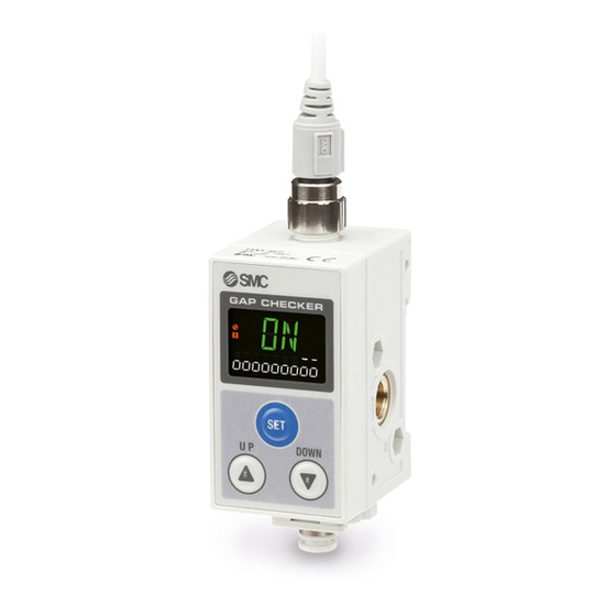
Page 15: Summary Of Product Parts
About this product Summary of Product parts Element Description Display See below Selects the mode and the display shown on the sub screen, or increases the switch UP button ( button) point. SET button ( button) Press this button to change the mode and to fix the settings. Selects the mode and the display shown on the sub screen, or decreases the switch DOWN button ( button) -
Page 16: Specification
About this product Specification ■ Specifications (ISA3) Model ISA3-F ISA3-G ISA3-H Dry air (Filtered through a 5 μm filter) Applicable fluid Rated distance range 0.01 to 0.03 mm 0.02 to 0.15 mm 0.05 to 0.30 mm Displayable/Settable range 2 2 2 0 to 60 10 to 300... -
Page 17: Specifications (Regulator)
About this product ■ Specifications (Regulator) Refer to the standard regulator catalogue for detailed specifications. ■ Specifications (2 port solenoid valve) Refer to "Option/Part number" (page 13) or the catalogue of the standard 2 port solenoid valve for the detailed specifications of models other than X276. -16- No.PS※※-OMR0002-G... -
Page 18: Characteristics Graph
About this product ■ Characteristics graph ○ Supply pressure dependence characteristics The detection distance for turning ON the output depends on the supply pressure. The graphs below show the variation of the distance for the product to turn ON, for 3 types of gap, by changing the supply pressure (50 kPa) when the product is set to turn ON at 150 kPa supply pressure. - Page 19 About this product ○ Response time Response time is the elapsed time between the pressure supply and the turning ON of the switch output. The Response time varies depending on the piping length from the OUT port to the detection nozzle, and the seating condition of the workpiece.
- Page 20 About this product ○ Relationship between the display value (switch point) and distance The graphs below show the relationship between [display value (switch point) on the sub screen] and [the actual distance between the detection surface and the workpiece]. Detection nozzle: ø1.5 Piping: F type: ø4 x ø2.5 tube 1 m, 3 m, 5 m Test conditions G, H type: ø6 x ø4 tube 1 m, 3 m, 5 m...
-
Page 21: Dimensions
About this product ■ Dimensions ISA3- (Without control unit, Bracket mounting) ISA-14 (Bracket when control unit not fitted) -20- No.PS※※-OMR0002-G... - Page 22 About this product ISA3- (Without control unit, DIN rail mounting) -21- No.PS※※-OMR0002-G...
- Page 23 About this product ISA3- B-L1 (With control unit, Bracket mounting) -22- No.PS※※-OMR0002-G...
- Page 24 About this product ISA3- ISA3- -B-R1 -B-R2 ISA3- ISA3- -B-LN -B-RN -23- No.PS※※-OMR0002-G...
- Page 25 About this product ISA-17 (Bracket when control unit fitted) Y200T-A (Spacer with bracket) ISA-20 (Bracket for centralized lead wire) -24- No.PS※※-OMR0002-G...
- Page 26 About this product ZS-31-B (Lead wire with connector (Straight)) ZS-31-C (Lead wire with connector (Right angle)) ISA-19- (Centralized lead wire) -25- No.PS※※-OMR0002-G...
-
Page 27: Mounting And Installation
Installation Mounting and Installation ■ Piping ○ SUP port (supply port) Use the correct tightening torque. Refer to the following table for the appropriate tightening torque. Fit the seal plug (supplied with the product) to the unused port. Nominal Proper tightening Nominal Proper tightening Product... - Page 28 Installation ○ Atmospheric vent port Connect tubing (sold separately) to the atmospheric vent port if there is a possibility that the port could be blocked by water or dust. Recommended tube is TU0425 (material: polyurethane, O.D. ø4, I.D. ø2.5) made by SMC. The other end of the air tubing should be routed to a safe place to prevent it from being exposed to water or dust.
-
Page 29: Installation
Installation ○ Restrictor setting of 2 port solenoid valve Air can be continuously supplied by adjusting the restrictor. This reduces the possibility of water or cutting oil etc. entering the 2 port solenoid valve from the OUT port (detection port). Turn off the power to the 2 port solenoid valve. - Page 30 Installation ■ Installation ○ DIN rail Mounting (1)Hook the claw part 1 to the DIN rail. (2)Push the claw part 2 down until it clicks. Removal (1)Pull the DIN rail mounting latch downward for unlocking. (2)Pull out the OUT port (detection port) side. -29- No.PS※※-OMR0002-G...
- Page 31 Installation ○ Bracket Mount the bracket using the mounting screws supplied. The tightening torque of the mounting screw must be 0.45 Nm ±10%. When the product is mounted using the bracket, fix with M5 screws (2 pcs.) or equivalent. The Bracket thickness is approx. 1.6 mm. Refer to the bracket dimension drawing (page 20) for the mounting hole dimensions.
- Page 32 Installation Mounting position of the bracket 2 stations n stations (Mount to 1st. and 2nd. station) (Mount to 1st. and nth. station) -31- No.PS※※-OMR0002-G...
- Page 33 Installation ○ Bracket (when control unit fitted) When a product with control unit is ordered, the bracket will be mounted to the product before shipment. Mount the spacer with bracket using an M5 mounting screw or equivalent. Thickness of the spacer with bracket is approximately 3.5 mm. Refer to the "Bracket mounting"...
- Page 34 Installation ○ Assembly procedure to increase/decrease the number of product. Remove the joint screws of product using a Phillips head screwdriver and separate the Product body. : Take care not to lose the seals. Insert a product and the seal for extra station (ISA-15) between the products to increase the number of stations.
-
Page 35: Wiring
Installation ■ Wiring ○ Mounting and removal of connector Tighten the connector by hand. Align the body connector key and the cable connector key groove to insert vertically. Turn the knurled part of the cable side connector clockwise. Connection is complete when the knurled part is fully tightened. Check that the connection is not loose. ○... - Page 36 Installation ○ Connector pin No. (Cable side) Connector pin No. Lead wire colour Description Brown DC(+) White N.C. Blue DC(-) Black OUT1 ZS-31-B ZS-31-C -35- No.PS※※-OMR0002-G...
- Page 37 Installation ISA-19- M12 Connector No. Pin No. Description Lead wire colour (Output wire colour) DC(+) Brown N.C. Black DC(-) Blue OUT1 DC(+) Brown N.C. White DC(-) Blue OUT1 DC(+) Brown N.C. Gray DC(-) Blue OUT1 ...
- Page 38 Installation ○ Internal circuit and wiring examples Wire the product according to the circuit diagram below. ISA3- ISA3- ◆Refer to the VX2 series Operation Manual for wiring details of the VX2 series (2 port solenoid valve). -37- No.PS※※-OMR0002-G...
-
Page 39: Part Structure
Installation ■ Part structure ○ Without control unit -38- No.PS※※-OMR0002-G... - Page 40 Installation ○ With control unit (Supply port: Left side) -39- No.PS※※-OMR0002-G...
- Page 41 Installation ○ With control unit (Supply port: Right side) -40- No.PS※※-OMR0002-G...
-
Page 42: Outline Of Setting
How to use Outline of setting Power is supplied The identification code of the product is displayed. Measurement mode Measurement mode starts automatically when supply pressure is between 80 and 220 kPa. Switch status ON or OFF will be displayed on the main screen. Level meter will be displayed on the sub screen (default setting). -
Page 43: Measurement Mode
How to use ■ Measurement mode Placement verification screen (Main screen) The Placement condition is indicated by the switch output status (ON/OFF). Level meter (Sub screen) Element Description A bar to indicate the switch point value which has been set, is automatically Switch point value bar displayed. - Page 44 How to use ○ Change of sub screen In measurement mode, the display of the sub screen can be temporarily changed by pressing the buttons 30 seconds after changing, the display will automatically return to the screen set in [F10] of function selection mode.
-
Page 45: Switch Point Setting
How to use Switch Point Setting ■ Switch point change mode The mode in which the switch point value can be changed. To change the hysteresis etc., refer to the function selection mode on page ■ Table of default settings Refer to the figure below for the default settings. -
Page 46: Preparation Before Setting
How to use ■ Preparation before setting (1)Supply pressure to the product. (100 to 200 kPa) (2)Insert a acceptable clearance gauge between the detection surface and the workpiece. Alternatively, place a sample workpiece (non-defective workpiece) on the detection nozzle. ■ Setting (1)Press the button while in measurement mode. -
Page 47: Function Setting
How to use Function Setting ■ Function selection mode In measurement mode, press the button for 2 seconds or longer to display [F 0]. Select to display the function to be changed, [F Press the button for 2 seconds or longer in function selection mode to return to measurement mode. <Operation>... - Page 48 How to use ○ [F 0] Units selection for pressure value Select the units for the pressure value to be indicated on the sub screen. This setting is only available for models with the units selection function. Units cannot be selected with the product number "-M".
- Page 49 How to use ○ [F 1]Setting the switch point, hysteresis, display colour Setting the switch point (P_1), hysteresis (H_1), and display colour. Refer to the figure below for the default settings. ISA3-F ISA3-G ISA3-H The switch output turns ON when the display value is less than switch point. (Solid line in the chart) The switch output turns OFF when the display value is greater than the switch point added to the hysteresis value.
- Page 50 How to use <Operation> : The display value on the main screen can be converted to the switch point setting by pressing the buttons simultaneously for 1 second or longer and releasing them (To reduce the setting operation). -49- No.PS※※-OMR0002-G...
- Page 51 How to use ○ [F 2] Not available "- - -" will be indicated on the sub screen. -50- No.PS※※-OMR0002-G...
- Page 52 How to use ○ [F 6] Display value compensation The display value can be corrected within 20% R.D. of the display value, at the time of shipment. <Operation> -51- No.PS※※-OMR0002-G...
- Page 53 How to use ○ [F10] Sub screen setting The sub screen indication during measurement mode can be selected from the following: Level meter, Display value, SUP side pressure, OUT side pressure, Switch point value and Display OFF can be selected. <Operation>...
- Page 54 How to use ○ [F80] Display OFF mode The display can be turned OFF to reduce power consumption. When no buttons have been pressed for 30 seconds, the display will shift to display OFF mode. While the display is OFF, the decimal points of the sub screen will flash. The default setting is "Display ON"...
- Page 55 How to use ○ [F81] Setting the security code for key-lock A security code can be selected, which must be entered to unlock the keys. When the security code has been set, the code entry is required to unlock the keys. Refer to page for key-lock and changing of the security code.
- Page 56 How to use ○ [F90]Setting of all functions The setting of all functions in function selection mode is available. <Operation> ●Order of function settings Order Function Applicable model This setting is only available for models with the units [Uni] Setting of pressure value units. selection function.
- Page 57 How to use ○ [F98] Forced output Forced output to test the product and the wiring. <Operation> -56- No.PS※※-OMR0002-G...
- Page 58 How to use ○ [F99] Reset to default settings The product can be returned to its factory default settings. <Operation> -57- No.PS※※-OMR0002-G...
-
Page 59: Key Lock (Security Code Setting)
How to use Key lock (Setting security code) <Operation> Select security code [ on] in function selection mode [F81] Perform key-lock in measurement mode. Release the key-lock. The security code is requested. The default setting is [000]. Press the button for 1 second when the security code is [000]. ... -
Page 60: Maintenance
Troubleshooting Maintenance Nozzle Cleaning The OUT port orifice can be removed for cleaning by removing the retaining screw. Flush inside the orifice with air or wipe off foreign matter with a soft clean cloth. Correct detection may not be possible if the orifice is dirty or scratched. (1)Remove the screw (2 pcs.) at the side of the OUT port. -
Page 61: Troubleshooting
Troubleshooting Troubleshooting If an operation failure of the product occurs, please confirm the cause of the failure from the following table. If a cause applicable to the failure cannot be identified and normal operation can be recovered by replacement with a new product, this indicates that the product itself was faulty. Problems with the product may be due to the operating environment (installation etc). -
Page 62: Error Indication
Troubleshooting ■ Error indication Main screen Error Name Description Measures Supply rated pressure. (100 kPa to Displayed when supply pressure is 200 kPa) Supply pressure error not in the range 80 kPa to 220 kPa. The product will return to Measurement is not possible. - Page 63 Revision history A: Contents are added. B: Modified errors in text. C: Additional model. D: Modified errors in text. E: Contents revised in several places. F: Contents revised in several places. G: Contents are added.[March 2018] Note: Specifications are subject to change without prior notice and any obligation on the part of the manufacturer. ©...
Need help?
Do you have a question about the ISA3-G series and is the answer not in the manual?
Questions and answers