
Subscribe to Our Youtube Channel
Related Manuals for Jetter JetWeb JX2-IA4


Summary of Contents for Jetter JetWeb JX2-IA4
- Page 1 JetWeb JX2-IA4 Operator’s Manual Article # 608 633 16 April 2002 / Printed in Germany...
- Page 2 JetWeb Edition 1.1 Jetter AG reserves the right to make alterations to its products in the interest of technical progress. These alterations need not be documented in every single case. This manual and the information contained herein have been compiled with due diligence.
- Page 3 This Manual is an Integral Part of the JetWeb Module JX2-IA4: Model: Serial Number: Year of Manufacture: Order Number: To be entered by the customer: Inventory Number: Place of Operation: © Copyright 2002 by Jetter AG. All rights reserved. Jetter AG...
- Page 4 Missing or inadequate knowledge of the manual results in the loss of any claim of liability on part of Jetter AG. Therefore, the operating company is recommended to have the instruction of the persons concerned confirmed in writing.
-
Page 5: Table Of Contents
JX2-IA4 Table of Contents Table of Contents Safety Instructions Ensure Your Own Safety Instructions on EMI Physical Dimensions Operating Parameters Technical Data JX2-IA4 Module - Analog Inputs Description of Connections Registers of the JX2-IA4 Module Jetter AG... - Page 6 Table of Contents JetWeb Jetter AG...
-
Page 7: Safety Instructions
The JX2-IA4 module is maintenance-free. Therefore, for the operation of the module no inspection or maintenance are required. Decommissioning and Disposal of the JX2-IA4 Module Decommissioning and disposal of the JX2-IA4 module are subject to the environmental legislation of the respective country in effect for the operator's premises. Jetter AG... - Page 8 · / - Enumerations are marked by full stops, strokes or scores. Operating instructions are marked by this arrow. Automatically running processes or results to be achieved are marked by this arrow. Illustration of PC and user interface keys. Jetter AG...
-
Page 9: Ensure Your Own Safety
For safety reasons, no modifications and changes to the JX2-IA4 module and its functions are permitted. Any modifications to the module not expressly authorised by the manufacturer will result in a loss of any liability claims to Jetter AG. The original parts are specially designed for the JX2-IA4 module. Parts and equipment of other manufacturers are not tested on our part, and are, therefore, not released by us. -
Page 10: Instructions On Emi
Only use metallised connectors, e.g. SUB-D with metallised housing. Please take care of direct connection of the strain relief with the housing here as well (refer to Fig. 1). Fig. 1: Shielding of SUB-D connectors in conformity with the EMC standards. Jetter AG... -
Page 11: Physical Dimensions
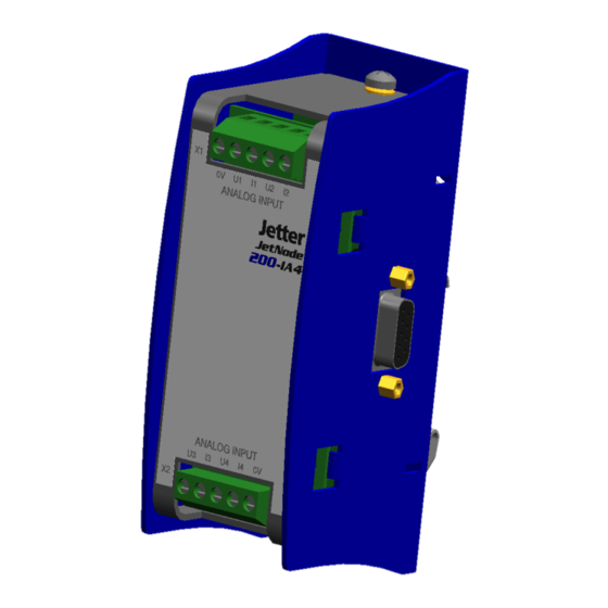
JX2-IA4 2 Physical Dimensions Physical Dimensions Fig. 2: Front View - JX2-IA4 Fig. 3: Side View - JX2-IA4 Jetter AG... - Page 12 JetWeb Fig. 4: Top View - JX2-IA4 Jetter AG...
-
Page 13: Operating Parameters
Shock Resistance 15 g occasionally, 11 ms, DIN EN 61131-2 sinusoidal half-wave, 2 shocks IEC 68-2-27 in all three spatial axes Degree of Protection IP20, rear: IP10 DIN EN 60529 Mounting Position Any position, snapped on DIN Rail Jetter AG... - Page 14 AM 80 % with 1 kHz Criterion A Discharge through air: DIN EN 61000-6-2 Test peak voltage 15 kV DIN EN 61131-2 (Humidity Rating RH-2 / ESD-4) DIN EN 61000-4-2 Contact Discharge: Test peak voltage 4 kV (severity level 2) Criterion A Jetter AG...
- Page 15 DIN EN 61000-4-6 AM 80 % with 1 kHz Source impedance 150 Ohm Criterion A Burst Test voltage 2 kV DIN EN 61131-2 tr/tn 5/50 ns DIN EN 61000-6-2 Repetition rate 5 kHz DIN EN 61000-4-4 Criterion A Jetter AG...
- Page 16 JetWeb Jetter AG...
-
Page 17: Technical Data
0 ... 20 mA Value range (current) 0 ... 2047 220 Ω Input impedance - Current Resolution (voltage) 12 Bit Resolution (current) 11 Bit Sampling interval < 13 ms Heat loss of CPU logic circuit 0.3 W Electrical isolation None Jetter AG... - Page 18 48.8 mV ± 10 LSB 98 µA – Current ± 10 LSB Gain Error: – Unipolar 24.4 mV ± 10 LSB – Bipolar 48.8 mV ± 10 LSB 98 µA – Current The typical measuring accuracy is higher. Jetter AG...
-
Page 19: Jx2-Ia4 Module - Analog Inputs
Apply to the analog inputs of the JX2-IA4 module a maximum voltage of DC 12 V, or a maximum current of 50 mA. This will prevent the JX2-IA4 module and the sensor, e.g. a temperature sensor, from being destroyed. Jetter AG... - Page 20 The shielding must be clamped under a strain relief with the greatest possible surface area. • The connection between shielding and ground must be electrically conducting. • The distance "L" of unshielded conductor ends must not exceed 8 cm. Jetter AG...
-
Page 21: Registers Of The Jx2-Ia4 Module
Example: Determination of the register numbers The number of the third expansion module’s register is determined as follows: Module number = 4 Local register number = 9 Register number = 3029 + (4-2) * 10 +9 = 3003 Jetter AG... - Page 22 To carry out measurements, the virtual outputs for the respective measuring method (unipolar, bipolar, current) have to be set in the program. The assignment can be seen from table "Configuring Inputs and Outputs" on page 22. Comments on the approach for task # 1: Jetter AG...
- Page 23 Unipolar Bipolar Current Channel # 1 3000 201 = 0 205 = 0 Channel # 2 3001 202 =0 206 =1 Channel # 3 3002 203 = 1 Channel # 4 3003 204 = 0 208 = 0 Jetter AG...
- Page 24 Register 3yy2: Channel # 3 for input voltage/current Function Description Read Present value for input voltage/current Value following reset: Present value for applied input voltage/current Write Illegal Value range Voltage - unipolar: 0 ... 4095 - bipolar: -2048 ... 2047 Current: 0 ... 2047 Jetter AG...
- Page 25 0 ... 4095 - bipolar: -2048 ... 2047 Current: 0 ... 2047 Register 3yy9: Version number of the operating system Function Description Read Version number of the operating system e.g. 101= V 1.01 Write Illegal Value range 32-bit-signed integer Jetter AG...
Need help?
Do you have a question about the JetWeb JX2-IA4 and is the answer not in the manual?
Questions and answers