Advertisement
Available languages
Available languages
Quick Links
Jetter AG
Gräterstraße 2
D-71642 Ludwigsburg E-Mail - Hotline:
Germany
Artikel-Nr.: 60879893 | Version 1.10
1 x
10000902 JX3-COM-PND
1 x
60870409 2-poliger Stecker, Zugfederanschluss
10 x
60870411 Klemmenmarkierer
1 x
60879893 Installationsanleitung
JX3-COM-PND
Kommunikationsmodul
Kontakte:
E-Mail - Vertrieb: sales@jetter.de
Telefon - Hotline: +49(0)7141/2550-
Installationsanleitung
Juli 2017 / Printed in Germany
Laden Sie die Betriebsanleitung
von www.jetter.de unter Downloads
herunter.
Lieferumfang
hotline@jetter.de
444
Advertisement

Related Manuals for Jetter JX3-COM-PND


Summary of Contents for Jetter JX3-COM-PND
- Page 1 JX3-COM-PND Kommunikationsmodul Jetter AG Kontakte: Gräterstraße 2 E-Mail - Vertrieb: sales@jetter.de D-71642 Ludwigsburg E-Mail - Hotline: hotline@jetter.de Germany Telefon - Hotline: +49(0)7141/2550- Installationsanleitung Artikel-Nr.: 60879893 | Version 1.10 Juli 2017 / Printed in Germany Laden Sie die Betriebsanleitung von www.jetter.de unter Downloads herunter.
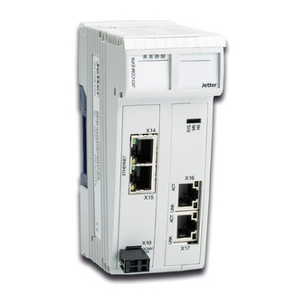
- Page 2 Modulseite) JX3-Backplane-Modul Stecker JX3-Modulgehäuse X16, X17 sind Ethernet-Ports für PROFINET IO (rechte Modulseite) Entriegelungslasche Untere Rastlaschen (in Abbildung nicht sichtbar) X10 für die Spannungsversorgung 10 X14, X15 sind Ethernet-Ports für Jetter- Ethernet-Systembus (linke Modulseite) 11 LEDs des Busknotens (linke Modulseite)
- Page 3 Montage auf Hutschiene EN 50022 Schritt Vorgehen Setzen Sie das Modul JX3-COM-PND auf die Hutschiene oben auf. Bewegen Sie das JX3-COM-PND in Pfeilrichtung, bis es auf der Hutschiene einrastet. Das JX3-COM-PND sitzt nun fertig montiert auf der Hutschiene.
- Page 4 Einstellen der IP-Adresse Schritt Vorgehen Schalten Sie das Modul JX3-COM-PND spannungslos. Drücken Sie auf die oberen und unteren Rastlaschen. Ziehen Sie das JX3-Gehäuse des JX3-COM-PND nach vorne ab. Auf dem JX3-Backplane- Modul sind nun die DIP-Schalter (1) erreichbar.
- Page 5 1 2 3 4 5 6 7 8 9 10 11 12 Setzen Sie das JX3-Gehäuse des JX3-COM-PND wieder auf das JX3-Backplane-Modul. Versorgen Sie das JX3-COM-PND wieder mit Spannung. Stellen Sie in JetSym die Adresse des PROFINET IO Device ein.
- Page 6 LEDs Farbe Beschreibung Betriebssystem grün läuft Allgemeiner Fehler Spezielle Zustände Bootloader läuft grün-gelb System läuft (grüne LED leuchtet) Systemfehler Busfehler...
- Page 7 LED-Zustände des JX3-COM-PND beim Einschalten Stufe Beschreibung Reset Der Bootloader lädt und überprüft das Betriebssystem. Das Betriebssystem liest die DIP-Schalter auf dem JX3-Backplane-Modul und prüft das Vorhandensein des Ethernet-Switches. Das Betriebssystem initialisiert Ethernet-Schnittstelle und Dateisystem. Das Betriebssystem initialisiert den Jetter- Ethernet-Systembus.
- Page 8 Status der LEDs des PROFINET IO Device nach erstmaligem Einschalten Beschreibung SYS-LED leuchtet grün. SF-LED ist aus. BF-LED leuchtet rot. Hinweis: Der LED-Status kann je nach Konfiguration abweichen. LED-Zustände des PROFINET IO Device Zustand Beschreibung Die SYS-LED leuchtet grün. Das Betriebssystem läuft fehlerfrei.
- Page 9 LED-Zustände des PROFINET IO Device Zustand Beschreibung Die SF-LED blinkt zyklisch mit 2 Hz, 3 s lang. Ein DCP-Signal-Service wird über den Bus ausgelöst. Die BF-LED ist aus. Es ist kein Busfehler vorhanden. Die BF-LED leuchtet rot. Einer der folgenden Fehler liegt vor: Die Konfiguration fehlt ...
- Page 10 Anschlussbeschreibung X10 Klemmpunkt Beschreibung X10.DC24V Versorgungsspannung für das Modul JX3-COM-PND. X10.0V Bezugspotenzial Technische Daten X10 Spannungsbereich: DC 24 V, -15 % ... +20 % Leistungsaufnahme: Max. 0,3 A x 24,0 V = 7,2 W Potenzialtrennung: Keine Leiteranschluss X10 Technologie: Zugfederanschluss...
- Page 11 Buchse X14, Ethernet-Port Jetter-Ethernet-Systembus Buchse X15, Ethernet-Port Jetter-Ethernet-Systembus LED LINK: X14 ist mit dem Jetter-Ethernet-Systembus verbunden LED ACT: JX3-COM-PND sendet oder empfängt über LED LINK: X15 ist mit dem Jetter-Ethernet-Systembus verbunden LED ACT: JX3-COM-PND sendet oder empfängt über Technische Daten X14/X15 Übertragungsrate:...
- Page 12 Anschlussbeschreibung X16/X17 Nummer Beschreibung LED RX/TX: JX3-COM-PND sendet oder empfängt über X16 LED LINK: X16 ist mit PROFINET IO verbunden LED RX/TX: JX3-COM-PND sendet oder empfängt über X17 LED LINK: X17 ist mit PROFINET IO verbunden Buchse X16, PROFINET-IO-Port Buchse X17,...
-
Page 13: Communication Module
+49(0)7141/2550- Installation Manual Item # 60879893 | Revision 1.10 July 2017 / Printed in Germany Download the user manual from www.jetter.de, Downloads. Scope of delivery 10000902 JX3-COM-PND 60870409 2-pin connector, spring-cage connection 10 x 60870411 Terminal labels 60879893 Installation Manual... - Page 14 Lower latches (not visible in the illustration) X10 for power supply 10 X14 and X15 are Ethernet ports for the Jetter Ethernet system bus (left hand side of the module) 11 LEDs of the bus node (left hand side of the module)
- Page 15 Installation on DIN rail to EN 50022 Step Action Place the module JX3-COM-PND on the upper edge of the DIN rail. Move the JX3-COM-PND in the direction of the arrow until it snaps into place. Installation of the JX3-COM-PND on the DIN rail is now completed.
- Page 16 Setting the IP address Step Action Remove power from the JX3-COM-PND. Press the upper and lower latches. Pull off the JX3 enclosure of the JX3-COM-PND. Now, the DIP switches (1) on the JX3 backplane module can be accessed.
- Page 17 Setting the IP address Step Action Set the IP address of the bus node (on the side of the Jetter Ethernet system bus) using the DIP switches (1 ... 12). IP address: 192.168.1.1 - Factory settings 1 2 3 4 5 6 7 8 9 10 11 12 IP address: 192.168.10.15...
- Page 18 LEDs Color Description OS is running Green Generic error Special conditions Boot loader is running System is running Green/ (green LED is lit) amber System error Bus error...
- Page 19 LED indications when the JX3-COM-PND is switched on Step Description Reset Boot loader is running and is checking the OS. The OS reads the settings of the DIP switch on the JX3 backplane module and checks if an Ethernet switch exists.
- Page 20 LED indications of the PROFINET IO Device after first power-up Description SYS is lit green. SF is off. BF is lit red. Note: Depending on the configuration, LED indications may vary. LED indications of the PROFINET IO Device State Description SYS is lit green.
- Page 21 LED indications of the PROFINET IO Device State Description BF is off. No bus error. BF is lit red. One of the following errors is present: Missing configuration Missing physical connection Physical connection is too slow. BF is flashing at 2 Hz. No data exchange possible.
- Page 22 Connector X10 - Description Terminal Description point X10.DC24V Power supply for module JX3-COM-PND X10.0V Reference potential Connector X10 - Technical data Input voltage range: DC 24 V -15 % ... +20 % Power consumption: 0.3 A x 24.0 V = 7.2 W max.
- Page 23 Connectors X14/X15 - Description Number Description X14 - Ethernet port Jetter Ethernet system bus X15 - Ethernet port Jetter Ethernet system bus LED LINK: X14 is connected with the Jetter Ethernet system bus LED ACT: JX3-COM-PND is transmitting or receiving...
- Page 24 Connectors X16/X17 - Description Number Description LED RX/TX: JX3-COM-PND is transmitting or receiving signals via X16 LED LINK: X16 is connected with PROFINET IO LED RX/TX: JX3-COM-PND is transmitting or receiving signals via X17 LED LINK: X17 is connected with PROFINET IO...