
Subscribe to Our Youtube Channel
Related Manuals for Jetter JetWeb JX2-CNT1


Summary of Contents for Jetter JetWeb JX2-CNT1
- Page 1 JX2-CNT1 Peripheral Module User Manual Item # 608 633 15 / Revision 3.02.4 June 2010 / Printed in Germany...
- Page 2 Introduction JetWeb Rev. 3.02.4 Jetter AG reserve the right to make alterations to its products in the interest of technical progress. These alterations will not necessarily be documented in every single case. This manual and the information contained herein have been compiled with due diligence.
-
Page 3: Jetter Ag
This User Manual is an Integral Part of the JetWeb-Module JX2-CNT1: Type: Serial #: Year of manufacture: Order #: To be entered by the customer: Inventory #: Place of operation: © Copyright 2010 by Jetter AG. All rights reserved. Jetter AG... - Page 4 Missing or inadequate knowledge of the manual results in the loss of any claim of liability on part of Jetter AG. Therefore, the operating company is recommended to have the instruction of the persons concerned confirmed in writing.
- Page 5 You have to wear goggles. Failure to comply may lead to bodily injuries. Warning This sign is to indicate a possible impending situation which might bring damage to the product or to its surroundings. It also identifies requirements necessary to ensure faultless operation. Important Jetter AG...
- Page 6 Reference to PC keyboard and HMI keys. Reference to a program or file. This symbol informs you of additional references (data sheets, literature, etc.) associated with the given subject, product, etc. It also helps you to find your way around this manual. Jetter AG...
-
Page 7: Table Of Contents
General Information Sample Circuitry Single-Channel Counter 6.6.1 Description of Connections 6.6.2 Description of LEDs Dual-channel counter 6.7.1 Description of Connections - Encoder Signals 6.7.2 Description of Connections - Reference Switch and Strobe Input 6.7.3 Description of LEDs SSI Encoder Jetter AG... - Page 8 Reading in SSI data 11.1.1 Standard Format 11.1.2 Fir-Tree Format 11.1.3 Left- and Right-Justified Data Format 11.1.4 Reading-In Data Formats 11.2 Configuration 11.2.1 Number and Rate of Clocks 11.3 Reversal of Counting Direction 11.4 Parity Check 11.5 Reference Offset Frequency Measurement Jetter AG...
-
Page 9: Master-Slave Operation
JX2-CNT1 Table of Contents 12.1 Sample Program Master-Slave Operation 13.1 Mode 1 - Operation along with JX2-SV1, etc. 13.2 Mode 2 - Operation along with JM-2xx Jetter AG... - Page 10 Table of Contents JetWeb Jetter AG...
-
Page 11: Safety Instructions
(SSI) are evaluated. The single-channel counter is for counting events. The module JX2-CNT1 is supplied with power from the Jetter system bus, that is, by the basic unit - the controller - in the case of centralized arrangement. In the case of remote arrangement by the power supply module JX2-PS1. -
Page 12: Who Is Permitted To Operate The Jx2-Cnt1 Module
The installation of such parts may impair the safety and the proper functioning of the JX2-CNT1 module. Any liability on the part of Jetter AG for any damages resulting from the use of non original parts and equipment is excluded. -
Page 13: Decommissioning And Disposal Of The Jx2-Cnt1 Module
JX2-CNT1 1.1 Generally Valid Safety Instructions 1.1.6 Decommissioning and Disposal of the JX2-CNT1 Module Decommissioning and disposal of the JX2-CNT1 module are subject to the environmental legislation of the respective country in effect for the operator's premises. Jetter AG... -
Page 14: Ensure Your Own Safety
Only qualified experts are allowed to carry out repairs. 1.2.2 Information Signs and Labels Markings, information signs, and labels always have to be observed and kept readable. Damaged or unreadable information signs and labels have to be replaced. Jetter AG... -
Page 15: Instructions On Emi
Connect the JX2-CNT1 module to the controller or the power supply module JX2-PS1 via Jetter system bus. Connect the JX2-CNT1 module to the Jetter system bus by directly plugging it into a JX2 module (not through a cable). The system bus can be extended by means of a cable. - Page 16 DIR ST S 0V POWER OUTPUT INPUT STOP Jetter Jetter DC 24 V ENCODER Nano-B JX2-CNT1 STEP INPUT COUNTER IN ANALOG OUT 0V OUT 0V Incremental encoder Fig. 2: Shielding of screw terminals in conformity with the EMC standards. Jetter AG...
- Page 17 The shielding must be clamped under a strain relief with the greatest possible surface area. • The connection between shielding and ground must be electrically conducting. • The length of unshielded conductor ends must not exceed 8 cm (refer to Fig. 2). Jetter AG...
- Page 18 1 Safety Instructions JetWeb Jetter AG...
-
Page 19: Introduction
The position obtained from position capturing can be evaluated in the application program or be sent via system bus as set position (master position) to an axis controller by Jetter AG. The single-channel counter is used e.g. as workpiece counter. -
Page 20: Update Information
2.3 Update Information JetWeb Update Information It is not possible to update the operating system of JX2-CNT1 modules from JetSym. The operating system can be updated only by Jetter AG. System Requirements Software Versions Module Minimum Software Version JX2-CNT1 3.02... -
Page 21: Physical Dimensions
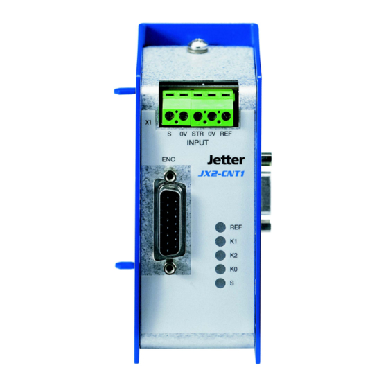
JX2-CNT1 3 Physical Dimensions Physical Dimensions Fig. 3: Front View - JX2-CNT1 Fig. 4: Side View - JX2-CNT1 Jetter AG... - Page 22 JetWeb Fig. 5: Top View - JX2-CNT1 Design Connection to the basic unit via Jetter Male connector SUB-D, 9 pins system bus Encoder connection Female connector SUB-D, 15 pins Counter Connection COMBICON terminal block Dimensions (H x W x D in mm)
-
Page 23: Operating Conditions
Shock Resistance 15 g occasionally, 11 ms, DIN EN 61131-2 sinusoidal half-wave, 2 shocks in IEC 2/27/1968 all three spatial axes Degree of Protection IP20, rear: IP10 DIN EN 60529 Mounting Position Any position, snapped on DIN rail Jetter AG... - Page 24 DIN EN 61000-6-2 Test peak voltage 15 kV DIN EN 61131-2 (Humidity Rating RH-2 / ESD-4) DIN EN 61000-4-2 Contact Discharge: Test peak voltage 4 kV (severity level 2) Criterion A Operating Parameters (EMC) - Signal Ports Parameter Value Reference Jetter AG...
- Page 25 DIN EN 61000-6-2 AM 80% at 1 kHz Source impedance 150 Ohm Criterion A Burst (fast transients) Test voltage 2 kV DIN EN 61131-2 tr/tn 5/50 ns DIN EN 61000-6-2 Repetition frequency 5 kHz DIN EN 61000-4-4 Criterion A Jetter AG...
- Page 26 JetWeb Jetter AG...
-
Page 27: Technical Data
200 mA max. (module logic circuit and bus) sensor supply) ≤ 0.5 W Power dissipation of logic circuit Connection to System Bus Connection to the basic unit via system Male connector SUB-D, 9 pins Module code on the system bus Jetter AG... - Page 28 24 V Operating Point - Low level: up to 2 V - High level: 20 V ... 30 V Input current 6 mA max. Electrical isolation None Counting method Single evaluation Selection of counting direction Yes, via software Jetter AG...
- Page 29 - Low level: up to 10 V - High level: 15 V ... 30 V Input current Max. 10 mA per channel (K0, K1, K2) Electrical isolation None Counting method Quadruple evaluation Selection of counting direction Yes, via hardware (reversal of K1 and K2) Jetter AG...
- Page 30 10 - 24 bits Type of signal decoding Gray-code and binary code Accepted data formats - Standard format - Left-justified - Right-justified - Fir-tree format Parity bit evaluation Yes, maximum: one parity bit Selection of counting direction Yes, via software Jetter AG...
-
Page 31: Installation Guide
NANO-A/B/C/D, etc., using a system bus cable. Connect any further expansion modules using the correct cable. Launch JetSym and set the communication parameters. Switch the controller on and download a JetSym program from your computer to your controller. Check the module for correct functioning. Jetter AG... -
Page 32: Notes On Safety As Regards The Installation
Before carrying out installation and maintenance jobs, isolate the module and all devices connected to it from the mains. Avoid damages caused by electrostatic discharge by touching grounded points before carrying out installation work. Damages caused by ESD do not always become immediately apparent! Jetter AG... -
Page 33: Notes On Safety As Regards Commissioning
Protect the JX2-CNT1 module and the equipment connected to it against accidental contact with live parts and components; Always carry out each commissioning, even a short functional test, with correctly connected PE bus; Ensure a durable connection between controller, module and expansion modules connected to it. Jetter AG... -
Page 34: General Information
DIR ST S 0V POWER OUTPUT INPUT STOP Jetter Jetter DC 24 V ENCODER Nano-B JX2-CNT1 STEP INPUT COUNTER IN ANALOG OUT 0V OUT 0V Incremental encoder Fig. 6: Diagram of input wiring of a JX2-CNT1 module with NANO-B Jetter AG... -
Page 35: Single-Channel Counter
Not needed Cable Shielding Make sure that the signal lines are shielded (see Fig. 6): • Clamp the shield with the greatest possible surface area under the grounding clamp and establish an electroconductive connection with the grounding block. Jetter AG... -
Page 36: Description Of Leds
X21.0V Reference potential Fig. 8: Connection of single-channel counter to terminal block X21 6.6.2 Description of LEDs Signal LED - Single-Channel Counter Color State Function amber Low level of counter input is lit High level of counter input Jetter AG... -
Page 37: Dual-Channel Counter
Do not connect DC 5 V (-5%), Power supply for encoders with operating voltage DC 5 V, short- circuit proof up to 100 mA Do not connect Do not connect Do not connect Do not connect Do not connect Jetter AG... - Page 38 Do not connect Channel A Do not connect K2 + Channel B Do not connect Do not connect Do not connect Do not connect Do not connect Do not connect Do not connect Do not connect Do not connect Jetter AG...
- Page 39 - Dual-Channel Counter 24 V, single-ended: approx. 20 m - Single-channel counter 24 V: approx. 20 m • Other specifications: see specifications of cables on encoder side Cable Shielding • Connect the shield with the greatest possible surface area to the metallized housing. Jetter AG...
-
Page 40: Description Of Connections - Reference Switch And Strobe Input
DC 24 V, max. 6 mA INPUT - Low level: up to 2 V - High level: 20 V ... 30 V X21.0V Reference potential for both inputs Fig. 10: Connection of strobe sensor and reference switch to X21 Jetter AG... -
Page 41: Description Of Leds
(inverted low level applied to channel B) amber Low level applied to channel N (zero pulse) (inverted high level applied to channel N) is lit High level applied to channel N (zero pulse) (inverted low level applied to channel N) Jetter AG... -
Page 42: Ssi Encoder
Gray-coded encoder value. In the case of Gray- coding this error has fatal effects: The module fails to produce continuous position values which, therefore, cannot be used. In the case of binary coding the counting direction is reversed. Jetter AG... - Page 43 X 21 S 0 V STR 0 V REF INPUT When reading in an SSI encoder, the strobe input X21.STR must be open- circuited. Otherwise errors may occur when reading in the position values from the SSI encoder. Jetter AG...
-
Page 44: System Bus
Power supply of these 5 expansion modules is provided by the controller. – Electrical and mechanical connection is established via SUB-D connector. These connectors excel by their reliable mechanical and electrical connections, as well as good EMI characteristics. Jetter AG... -
Page 45: Remote Arrangement On The System Bus
0 V 0 V 8 0 V 8 0 V 8 0 V Fig. 11: Centralized arrangement on the Jetter System Bus 6.9.2 Remote Arrangement on the System Bus – Remote modules are located at a certain distance from the controller and JX2 expansion modules directly connected to it. -
Page 46: System Bus Cable Specification
System System System JX2-PS1 and modules JX2-PS1 and modules JX2-PS1 and modules Fig. 12: Remote Arrangement on the Jetter System Bus 6.9.3 System Bus Cable Specification Specification of Connector/Socket Male connector (BUS-OUT side - controller / expansion modules) • 9-pin male SUB-D connector in metallized housing (quality grade 3). - Page 47 The maximum cable length depends on the baud rate used and the number of modules connected to the bus. • When calculating the maximum line length, please take into account that each module connected to the bus reduces the cable length by approx. 1 m. Jetter AG...
- Page 48 Use metallized housing only! Signal CMODE0 CMODE1 TERM (not connected) Unassigned Unassigned Do not connect Ordering Information The system bus cable can be purchased from Jetter AG in various lengths. For more information refer to chapter 2.2 "Ordering Information", page 19. Jetter AG...
-
Page 49: Software Programming
Addressing in the case of JC-24x / NANO-A/B/C/D controllers: Output number: xxzz Meaning: I/O number: 01...08 I/O module number: 02...24 For more information, for example on register overlaying of outputs, refer to the User's Manual supplied with the corresponding controller. Jetter AG... - Page 50 Module # 1 is assigned to the basic controller. Starting from there, the module numbers are counted left to right. Basically, the granularity is 16. That means, for example, that 16 outputs are allocated to the JX2-CNT1 module, irrespective of the fact that only 8 virtual outputs can be addressed. Jetter AG...
- Page 51 Module # 2 Module # 3 Intelligent Module # 1 Module # 2 Input 101 .. 116 Input ! ! ! Output Outputs 101 .. 108 201 .. 208 JX2-SV1 Output Module 301 .. 308 201 .. 208 Jetter AG...
-
Page 52: Register Interface
The register address always starts with the area number 3. Register number: 3xxz Meaning: Register number: 0...9 I/O module number - 2: 0...22 JX2-I/O module area: 3 For more information refer to the manual on the corresponding controller. Jetter AG... - Page 53 To determine the I/O module number, only non-intelligent modules are counted, such as JX2-IO16, JX2-ID8, JX2-OD8, etc. Intelligent modules, such as JetMove 2xx, JetMove 6xx, JX2-SV1, JX2--SM2, JX2-PID1, etc., located among the digital input and output modules, are not taken into consideration. Jetter AG...
- Page 54 Determinig the register number of the third I/O expansion module connected to a JetControl-246: I/O module number = 4 Local register number = 9 Register number = 3000 + (4 - 2) * 10 + 9 = 3029 Jetter AG...
-
Page 55: Configuration And Diagnostics
Bit 2: Reserved Bit 3: Dual-channel counter - reference status Indicates whether the dual-counter count value has been zeroed. This value is reset by resetting output xx01. 0 = No zeroing 1 = Zeroing completed Value following reset: 0 Jetter AG... - Page 56 0 = Counting direction as per transmitted data (this is true for Gray coding. In the case of binary coding, the counting direction of the JX2-CNT1 module and the SSI encoder is inverted). 1 = Inverted counting direction Value following reset: 0 Bit 10 - Reserved bit 11: Jetter AG...
-
Page 57: Firmware Version
Description Read Version number of the operating system e.g. 101 = V 1.01 Write Illegal Value range 0 ... 8.388.607 Value following reset Version number of the operating system Note! Please state this number when making technical inquiries. Jetter AG... - Page 58 8.2 Firmware Version JetWeb Jetter AG...
-
Page 59: Single-Channel Counter
Register 3xx4: Single-Channel Counter - Count Value Function Description Read Present count value Write Defining the new count value Value range - 8,388,608 ... + 8,388,607 [pulses] Value following reset The count value can be changed by manually entering a value into register 3xx4. Jetter AG... - Page 60 JetWeb Jetter AG...
-
Page 61: Dual-Channel Counter
New count of dual-channel counter Value range - 8.388.608 ... + 8,388,607 [increments] Value following reset The count value can be changed by manually entering a value into register 3xx0, for example zero to reset the count to zero. Jetter AG... -
Page 62: Dual-Channel Counter As Single-Channel Counter
Fig. 13. The count value is incremented or decremented at every positive edge of the counting channel K1. The count value of the single-channel counter can be seen from register 3xx0 "Count value", or it can be changed there manually. Jetter AG... - Page 63 JX2-CNT1 10 Dual-Channel Counter Fig. 13: Signal waveform for single-channel counting Jetter AG...
-
Page 64: Referencing
REF input is already on low level. If no reference switch is connected to the module, the REF input is on low level by default. Jetter AG... -
Page 65: 10.4.2 Setting The Reference Offset
“Setting the Reference Position" on page 64). Register 3xx1 "Dual-channel counter - Offset" can be used to define any position as reference position (refer to “Reference Offset" on page 66). In this connection, the previously determined reference position of the mechanical system is maintained. Jetter AG... -
Page 66: Reference Offset
– The user enters 10,000 into register 3xx1. – The count value is set to 10,000 increments, or to a value around 10,000 if the incremental encoder has moved during this process or is between 2 PPR counts and is permanently oscillating. Jetter AG... -
Page 67: Digital Filter
The value corresponding to the desired fundamental frequency is calculated by the following formula: ⎛ 4000000 ⎞ × Register 3xx8 -------------------- - 1 at f in Hz – ⎝ ⎠ fund fund Jetter AG... -
Page 68: Strobe Function
3xx3. Register 3xx2: Dual-Channel Counter - Strobe Value Function Description Read Actual count value or value that has been stored last Write Illegal Value range - 8.388.608 ... + 8,388,607 [increments] Value following reset Jetter AG... -
Page 69: Ssi Absolute Encoder
The position value which has been read in can be seen from register 3xx0 "Count value". Output xx04 = 1 Register 3xx0: Count value Function Description Read Actual count value of the SSI encoder Write Illegal Value range Depending on the position resolution of the encoder Value following reset Jetter AG... -
Page 70: 11.1.1 Standard Format
Here, special bits or a parity bit can be added, as well. However, only after the zero bits which have been added to reach the required length, for example, starting from clock 25. Fig. 16: SSI - Fir-Tree Format Jetter AG... -
Page 71: 11.1.3 Left- And Right-Justified Data Format
Here, special bits or a parity bit can be added, as well. They can be placed directly after the position bits or after the trailing zero bits. Fig. 17: SSI - Left- or right justified data format Jetter AG... -
Page 72: 11.1.4 Reading-In Data Formats
In the case of a parity error, the position value contained in register 3xx0 is not updated. Therefore, this configuration is not allowed. Jetter AG... - Page 73 Due to the 25 clocks, the zero bit, which has been read out in cycle 1, is not taken into account when generating the position value. However, the special bit is included in the position value. To separate the special bit from the position value proceed according to example 5. Jetter AG...
- Page 74 11.1 Reading in SSI data JetWeb Fig. 18: Examples - Reading in Different SSI Formats Jetter AG...
-
Page 75: Configuration
The value of register 3xx6 (number of clocks and clock rate) is calculated by the formulas given in the following table. In this table, configuration values for clock rates of 100 kHz and 200 kHz along with the most common clock numbers are listed: Jetter AG... - Page 76 An SSI encoder is to be read out at a clock rate of 200 kHz and 20 clocks. A = (((20 + 1) x 2) - 1) x 1024 = 41,984 B = (16,000,000 / (200,000 x 2)) - 41 = -1 Register 3xx6 = 41,984 - 1 = 41,983 Jetter AG...
-
Page 77: Reversal Of Counting Direction
If the SSI encoder performs parity evaluation can be seen from the manual that comes with the encoder. If the JX2-CNT 1 module detects a parity error, the position value received is ignored (register 3xx0 "Count value" is not updated) and register 3xx7 "Counter of SSI parity errors" is incremented. Jetter AG... -
Page 78: Reference Offset
Note! If the counting direction is reversed by means of bit 9, the reference offset must be entered into register 3xx1 only after bit 9 has been set. Jetter AG... -
Page 79: Frequency Measurement
Status bit 12 = 1 Register 3xx7: Frequency - Display Function Description Read Present frequency value (for dual-channel counter or SSI encoder) Write Illegal Value range - 8,388,608 ... + 8,388,607 [increments / time interval] Value following reset Jetter AG... -
Page 80: Sample Program
REGISTER_LOAD (rmTimeBase, 100) ; time interval to 1 s BIT_CLEAR (rmStatusControl, nbSelectFrequency) ; +++ Speed Calculation ++++ ; +++ is executed at regular intervals +++ BIT_SET (rmStatusControl, nbSelectFrequency) REG rRPM = REG rmFrequency * 60 / 4096 BIT_CLEAR (rmStatusControl, nbSelectFrequency) Jetter AG... - Page 81 //***** Program ****************************************************** +++ Frequency Measurement Initialization +++ bnSelectFrequency:= TRUE; nmTimeBase:= 100; Time interval to 1 bnSelectFrequency:= FALSE; +++ Speed calculation - is executed at regular intervals +++ bnSelectFrequency:= TRUE; nRPM:= nmFrequency * 60 / 4096; bnSelectFrequency:= FALSE; Jetter AG...
- Page 82 12.1 Sample Program JetWeb Jetter AG...
- Page 83 JX2-CNT1 can be used as master axis for technological functions. The count as Master Axis value of the dual-channel counter or SSI encoder can be transmitted as master in Technological axis position for master/slave operation to one or more Jetter axis modules via Functions system bus. Important!
- Page 84 Select master/slave mode 1 on the JX2-CNT1. Procedure: Delete bit 14 "Master Mode - Selection" in register 3xx3 "Status / Controller" Define the transmission rate. Procedure: Enter the desired value into register 3xx5 "Transmission Rate - Actual Position" (see overleaf). Recommendation: 1 ms Jetter AG...
- Page 85 ;********** Output Symbols ************* oSendMasterPos Virtual output xx03 JetSym - Program Listing ;+++ Initializing Master/Slave Operation in Mode 1 +++ BIT_CLEAR (rmStatusControl, nbSelectMS_Modus2) ; if set REGISTER_LOAD (rmSendRate, 1) Transmission rate = 1 ms OUT oSendMasterPos Jetter AG...
- Page 86 Bit for selecting master/slave operation Outputs boSendMasterPos: BOOL AT %QX 203; Virtual output xx03 END_VAR; //***** Program ***************************************************** +++ Initializing Master/Slave Operation in Mode 1 +++ bnSelectMS_Modus2:= FALSE; // if set nmSendRate:= 1; Transmission rate = 1 ms boSendMasterPos:= TRUE; Jetter AG...
- Page 87 Below the steps are listed to configure a JX2-CNT1 as master axis in mode 2: Steps Step Action Select master/slave mode 2 on the JX2-CNT1. Procedure: Set bit 14 "Master Mode - Selection" in register 3xx3 "Status / Controller" Jetter AG...
- Page 88 Virtual output xx03 JetSym - Program Listing ;+++ Initializing Master/Slave Operation in Mode 2 +++ BIT_SET (rmStatusControl, nbSelectMS_Modus2) REGISTER_LOAD (rmMasternumber, 1) Master number = 1 OUT oSendMasterPos JetSym ST - Program Listing //***** Declaration of Variables ************************************** Register Jetter AG...
- Page 89 BOOL AT %VL 3003.14; Bit for selecting master/slave operation Outputs boSendMasterPos: BOOL AT %QX 203; Virtual output xx03 END_VAR; //***** Program ***************************************************** +++ Initializing Master/Slave Operation in Mode 2 +++ bnSelectMS_Modus2:= TRUE; nmMasternumber:= 1; Master number = 1 boSendMasterPos:= TRUE; Jetter AG...
- Page 90 13.2 Mode 2 - Operation along with JM-2xx JetWeb Jetter AG...
- Page 91 JX2-CNT1 Appendices Appendix Jetter AG...
- Page 92 Appendices JetWeb Jetter AG...
- Page 93 Signal Coding 1) Gray code 2) Page 75 0 = Gray code 1 = binary code xx07 Activation of Parity Check 1) Parity check disabled 2) Page 75 0 = parity check disabled 1 = parity check enabled Jetter AG...
- Page 94 Appendices JetWeb Output Name 1) Default value Number 2) Cross reference xx08 Parity Settings 1) odd parity 2) Page 75 0 = odd parity 1 = even parity Jetter AG...
- Page 95 JX2-CNT1 Appendices Jetter AG...
- Page 96 Bit 1: Reserved Bit 2: Reserved Bit 3: Dual-channel counter - reference status No zeroing Setting to zero completed Bit 4: Dual-channel counter - strobe overflow status No strobe overflow Strobe overflow Bit 5: Reserved Jetter AG...
- Page 97 14 = 0 3) Page 89 3xx5 Number of leading axis 1) 1 ... 2 Status bit 2) 0 14 = 1 3) Page 92 3xx6 SSI - configuration 1) 0; 21,464 ... 65,535 2) 0 3) Page 75 Jetter AG...
- Page 98 Status bit 2) 0 12 = 1 3) Page 77 3xx8 Dual-channel counter - 1) 0 ... 32,704 filtering frequency 2) 0 3) Page 67 3xx9 Firmware version 1) 0 .. 8,388,607 2) Firmware version 3) Page 57 Jetter AG...
- Page 99 JX2-CNT1 Appendices Jetter AG...
- Page 100 Hotline: +49 7141 2550-444 Internet: http://www.jetter.de E-Mail: sales@jetter.de Jetter Subsidiaries Jetter Asia Pte. Ltd. Jetter (Schweiz) AG Jetter USA Inc. 32 Ang Mo Kio Industrial Park 2 Münchwilerstraße 19 165 Ken Mar Industrial Parkway #05-02 Sing Industrial Complex CH-9554 Tägerschen...
Need help?
Do you have a question about the JetWeb JX2-CNT1 and is the answer not in the manual?
Questions and answers