Advertisement
Available languages
Available languages
Quick Links
Jetter AG
Gräterstraße 2
D-71642 Ludwigsburg E-Mail - Hotline:
Germany
Artikel-Nr.: 60871746 | Version 1.12
1 x
10000570 JX3-THI2-RTD
2 x
60869252 10-poliger Stecker, Zugfederanschluss
1 x
60870410 Kodierstifte
10 x
60870411 Klemmenmarkierer
1 x
60871746 Installationsanleitung
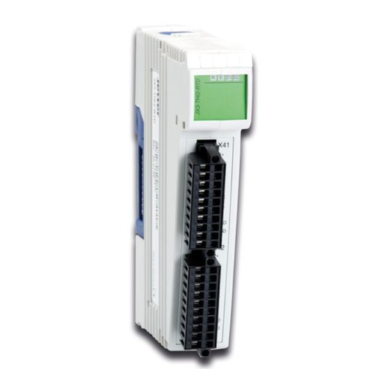
JX3-THI2-RTD
Temperaturmodul
Pt100/Pt1000
Kontakte:
E-Mail - Vertrieb: sales@jetter.de
Telefon - Hotline: +49(0)7141/2550-
Installationsanleitung
Juni 2016 / Printed in Germany
Laden Sie die Betriebsanleitung
von www.jetter.de unter Downloads
herunter.
Lieferumfang
hotline@jetter.de
444
Advertisement

Subscribe to Our Youtube Channel
Related Manuals for Jetter JX3-THI2-RTD


Summary of Contents for Jetter JX3-THI2-RTD
- Page 1 JX3-THI2-RTD Temperaturmodul Pt100/Pt1000 Jetter AG Kontakte: Gräterstraße 2 E-Mail - Vertrieb: sales@jetter.de D-71642 Ludwigsburg E-Mail - Hotline: hotline@jetter.de Germany Telefon - Hotline: +49(0)7141/2550- Installationsanleitung Artikel-Nr.: 60871746 | Version 1.12 Juni 2016 / Printed in Germany Laden Sie die Betriebsanleitung von www.jetter.de unter Downloads herunter.
- Page 2 Konfiguration Das Modul JX3-THI2-RTD ist direkt anschließbar an den JX3-Systembus. Es wird über ein JX3-BN-xxx, ein JX3-PS1 oder über eine JC-3xx mit Spannung versorgt. Montage Schritt 1 Schalten Sie zur Montage und Demontage alle JX3-Module der JX3-Station spannungslos.
- Page 3 LEDs leuchtet Alle grün: Spannungsversorgungen in Ordnung leuchtet Kommunikation zum rot: JX3-BN-xxx oder zur JC-3xx ist nicht aktiv blinkt kurz Betriebssystem ist nicht rot: gültig; Update durchführen leuchtet Kabelbruch, Kurzschluss, rot: Übertemperatur oder Untertemperatur auf mindestens einem Kanal blinken Betriebssystemupdate ist rot: aktiv...
- Page 4 Anschlussbeschreibung Klemmpunkt X41 Sensor IN X41.I1+ Stromanschluss Sensor 1 X41.U1+ Spannungsanschluss Sensor 1 X41.U1- Spannungsanschluss Sensor 1 X41.I1- Stromanschluss Sensor 1 X41.0V Masse X41.Br1 Frei X41.Br2 Frei X41.0V Masse X41.SHLD Schirmanschluss X41.SHLD Schirmanschluss Klemmpunkt X42 Sensor IN X42.I2+ Stromanschluss Sensor 2 X42.U2+ Spannungsanschluss Sensor 2 X42.U2-...
- Page 5 Anschlussbeschreibung X41, X42: Arbeiten unabhängig voneinander Dreileiter- Mode: Brücke I1+ mit U1+ bzw. I2+ mit U2+ Zweileiter- Brücken I1+ mit U1+ und I1- mit U1- bzw. I2+ Mode: mit U2+ und I2- mit U2- Die Eingänge X41 und X42 sind reine Wichtig! Messeingänge! Ein Anschließen einer aktiven Spannung oder eines Stroms an irgendeinem...
- Page 7 Item # 60871746 | Revision 1.12 June 2016 / Printed in Germany Download the user manual from www.jetter.de, Downloads. Scope of delivery 10000570 JX3-THI2-RTD 60869252 10-pin connector, spring-cage connection 60870410 Keying pins 10 x 60870411 Terminal labels 60871746 Installation Manual...
- Page 8 Configuration The module JX3-THI2-RTD can directly be connected to the JX3 system bus. It is supplied with power from a JX3-BN-xxx, JX3-PS1 or JC-3xx. Installation - Step 1 Disconnect all JX3 modules connected to the JX3 station from the power supply when installing or removing modules.
- Page 9 LEDs Green, lit: All power supplies are ok Red, lit: Communication with JX3-BN-xxx, or JC-3xx is not active Red, shortly flashing: OS not valid; update OS Red, lit: Cable breakage, short-circuit, excess or insufficient temperature on at least one channel Red, flashing: OS is being updated...
- Page 10 Description of connections Terminal X41 - Sensor IN point X41.I1+ Current supply - Sensor 1 X41.U1+ Voltage supply - Sensor 1 X41.U1- Voltage supply - Sensor 1 X41.I1- Current supply - Sensor 1 X41.0V Ground X41.Br1 Unassigned X41.Br2 Unassigned X41.0V Ground X41.SHLD Shielding connection...
-
Page 11: Description Of Connections
Description of connections X41, X42: They are not dependent on each other 3-wire connection: Jumper between I1+ and U1+ or I2+ and U2+ 2-wire Jumpers between I1+ and U1+ and between connection: I1- and U1- or I2+ and U2+ and between I2- and U2- Important! Inputs X41 and X42 are measurement inputs only! Connecting an active voltage or current...
Need help?
Do you have a question about the JX3-THI2-RTD and is the answer not in the manual?
Questions and answers