Jetter JX3-BN-CAN Installation Instructions Manual
Can bus node
Hide thumbs
Also See for JX3-BN-CAN:
- User manual (54 pages) ,
- Manual (4 pages) ,
- Installation manual (12 pages)
Advertisement
Available languages
Available languages
Quick Links
Download this manual
See also:
User Manual
Jetter AG
Gräterstraße 2
D-71642 Ludwigsburg E-Mail - Hotline:
Germany
1 x
10000544 JX3-BN-CAN
1 x
60870409 2-poliger Stecker, Zugfederanschluss
10 x
60870411 Klemmenmarkierer
1 x
60871026 Installationsanleitung
JX3-BN-CAN
CAN-Busknoten
Kontakte:
E-Mail - Vertrieb: sales@jetter.de
Telefon - Hotline: +49(0)7141/2550-
Installationsanleitung
Version 1.10
Artikel-Nr.: 60871026
März 2014 / Printed in Germany
Laden Sie die Betriebsanleitung
von www.jetter.de unter
Support > Downloads herunter.
Lieferumfang
hotline@jetter.de
444
Advertisement

Related Manuals for Jetter JX3-BN-CAN


Summary of Contents for Jetter JX3-BN-CAN
- Page 1 JX3-BN-CAN CAN-Busknoten Jetter AG Kontakte: Gräterstraße 2 E-Mail - Vertrieb: sales@jetter.de D-71642 Ludwigsburg E-Mail - Hotline: hotline@jetter.de Germany Telefon - Hotline: +49(0)7141/2550- Installationsanleitung Version 1.10 Artikel-Nr.: 60871026 März 2014 / Printed in Germany Laden Sie die Betriebsanleitung von www.jetter.de unter Support >...
- Page 2 Konfiguration Der Busknoten JX3-BN-CAN muss ganz links in der JX3-Station montiert sein. Die mögliche anschließbare Anzahl an JX3-Module ist abhängig von der Leistungsaufnahme und Adressbelegung der Module, siehe hierzu "JX3_sysbus_configurator". Die Datei steht zum Download auf der Homepage http://www.jetter.de zur Verfügung.
- Page 3 Montage Schritt 1 Schalten Sie zur Montage bzw. Demontage alle JX3-Module der JX3-Station spannungslos. Setzen Sie den JX3-BN-CAN auf die Hutschiene EN 50022 auf. Montage Schritt 2 Bewegen Sie den JX3-BN-CAN in Pfeilrichtung, bis er auf der Hutschiene einrastet. Montage Schritt 3 Schieben Sie die JX3-Station an den JX3-BN-CAN heran.
- Page 4 LEDs leuchtet Alle grün: Spannungsversorgungen sind in Ordnung leuchtet rot: Mindestens ein Fehlerbit ist im Statusmodulregister gesetzt blinkt rot: Mindestens eine interne Versorgungsspannung ist nicht in Ordnung blinkt Warten auf schnell rot: Inbetriebnahme aus: Verbindung zur Steuerung ist aktiv Betriebssystem ist nicht blinkt rot: gültig;...
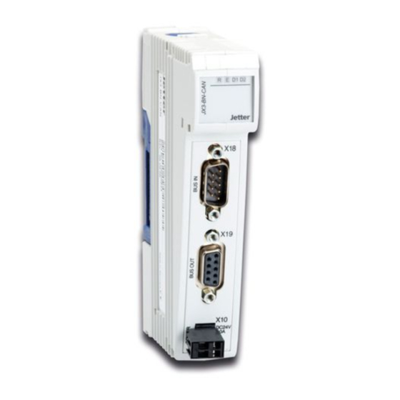
- Page 5 X19 Bus Out X19.1 CMODE0 X19.2 X19.3 X19.4 CMODE1 X19.5 TERM X19.6 Unbenutzt X19.7 X19.8 Unbenutzt X19.9 Nicht anschließen Versorgungsspannung X10.DC24V Versorgungsspannung X10.0V Bezugspotenzial Wichtig! Zum Abschalten des internen Busabschluss- widerstands müssen Sie Pin X19.5 mit Pin X19.3 am JX3-BN-CAN brücken.
- Page 6 ... 1,5 mm Aderendhülse mit Kragen: 0,2 mm ... 1,0 mm Technische Daten X10 Spannungsbereich: DC 24 V, -15 % ... +20 % Leistungsaufnahme: Max. 1,0 A x 24,0 V = 24 W Technische Daten X18/X19 Jetter-Systembusanschluss Steckertyp: Sub-D 9-polig...
-
Page 7: Installation Instructions
+49(0)7141/2550- Installation Instructions Revision 1.10 Item # 60871026 March 2014 / Printed in Germany The user manual can be downloaded from www.jetter.de at Support > Downloads. Scope of Delivery 10000544 JX3-BN-CAN 60870409 2-pin plug-in connector, spring cage technology 10 x 60870411 Terminal labels... - Page 8 Configuration The JX3-BN-CAN bus head has to be mounted at the very left side of the JX3 station. The maximum number of JX3 modules, that can be connected to a JX3 station, depends on the power consumption and address range assigned to the modules.
- Page 9 Mounting, Step 1 For mounting, respectively disassembling, de-energize all JX3 modules of the JX3 station. Place the module JX3-BN-CAN on top of the DIN rail EN 50022. Mounting, Step 2 Move the JX3-BN-CAN in the direction of the arrow until it snaps into place.
- Page 10 LEDs green, lit: All voltage supplies are red; lit: At least one error bit has been set in the status module register red; At least one internal flashing: voltage supply is not ok red; fast Waiting for flashing: commissioning Off: Connection to controller is active red;...
- Page 11 X19.4 CMODE1 X19.5 TERM X19.6 Unused X19.7 X19.8 Unused X19.9 Do not connect X10 Supply Voltage X10.DC24V Supply voltage X10.0V Reference potential Important! For deactivating the internal bus terminating resistor, you must short-circuit pin X19.5 with pin X19.3 at JX3-BN-CAN.
- Page 12 ... 1.0 mm X10 - Technical Data Voltage range: DC 24 V, -15 % ... +20 % Power consumption: 1.0 A x 24.0 V = 24 W max. X18/X19 - Technical Data Jetter system bus connection Connector type: 9-pin sub-D connector...
Need help?
Do you have a question about the JX3-BN-CAN and is the answer not in the manual?
Questions and answers