
Subscribe to Our Youtube Channel
Related Manuals for Jetter JX2-IO16


Summary of Contents for Jetter JX2-IO16
- Page 1 JX2-IO16 Peripheral Module User Manual Article # 608 706 14 / Revision 3.00.2 September 2006 / Printed in Germany...
- Page 2 JetWeb Revision 3.00.2 Jetter AG reserves the right to make alterations to its products in the interest of technical progress. These alterations need not be documented in every single case. This manual and the information contained herein have been compiled with due diligence.
- Page 3 This user manual is an integral part of the peripheral module JX2-IO16: Type: Serial #: Year of construction: Order #: To be entered by the customer: Inventory #: Place of operation: © Copyright 2006 by Jetter AG. All rights reserved. Jetter AG...
- Page 4 Significance of this User Manual This manual is an integral part of the JX2-IO16 module, and • must be kept in a way that it is always at hand until the JX2-IO16 module will be disposed of. • If the JX2-IO16 module is sold, alienated or loaned, this manual must be handed over.
- Page 5 JX2-IO16 Introduction Description of Symbols This sign is to indicate a possible impending danger of serious physical damage or death. Warning This sign is to indicate a possible impending danger of light physical damage. This sign is also to warn you of material damage.
- Page 6 PC and user interface keys. Reference to a program or file. This symbol informs you of additional references (data sheets, literature, etc.) associated with the given subject, product, etc. It also helps you to find your way around this manual. Jetter AG...
-
Page 7: Table Of Contents
Generally Valid Safety Instructions 1.1.1 Usage as Agreed Upon 1.1.2 Usage Other Than Agreed Upon 1.1.3 Who is Permitted to Operate the JX2-IO16 Module? 1.1.4 Modifications and Alterations to the Module 1.1.5 Repairing and maintaining the JX2-IO16 Module 1.1.6 Decommissioning and Disposal of the JX2-IO16 Module Ensure Your Own Safety 1.2.1... - Page 8 Overview of Registers 10.2 Operating principle 10.3 Manual pulse stretching 10.4 Automatic pulse stretching 10.5 Register Description Counter Function 11.1 Overview of Registers 11.2 General Information 11.3 Single-channel counter 11.4 Dual-channel counter 11.5 Frequency measurement 11.6 Register Description Jetter AG...
- Page 9 JX2-IO16 Table of Contents Diagnostic and Administrative Functions 12.1 Error Diagnosis 12.1.1 Error in System bus communication -Timeout 12.1.2 System bus communication error - Data buffer overflow 12.1.3 Error in the output circuit 12.2 Response of Digital Outputs to Timeout 12.3...
- Page 10 Table of Contents JetWeb Jetter AG...
-
Page 11: Safety Instructions
The JX2-IO16 module is a peripheral module featuring 8 digital inputs and 8 digital outputs and can be connected to the Jetter system bus. The supply voltage of the JX2-IO16 module is DC 24 V. This operating voltage is classified as SELV (Safety Extra Low Voltage). The JX2-IO16 module is therefore not subject to the EU Low Voltage Directive. -
Page 12: Who Is Permitted To Operate The Jx2-Io16 Module
The installation of such parts may impair the safety and the proper functioning of the JX2-IO16 module. Any liability on the part of Jetter AG for any damages resulting from the use of non original parts and equipment is excluded. -
Page 13: Decommissioning And Disposal Of The Jx2-Io16 Module
JX2-IO16 1.1 Generally Valid Safety Instructions 1.1.6 Decommissioning and Disposal of the JX2-IO16 Module Decommissioning and disposal of the JX2-IO16 module are subject to the environmental legislation of the respective country in effect for the operator's premises. Jetter AG... -
Page 14: Ensure Your Own Safety
1 Safety Instructions JetWeb Ensure Your Own Safety Disconnect the JX2-IO16 module from the mains to carry out maintenance work. By doing so, you will prevent accidents resulting from electric voltage and moving parts. Safety and protective devices, e.g. the barrier and cover of the terminal box must never be shunted or by-passed. -
Page 15: Instructions On Emi
Important! Measures for increasing immunity to interference: The JX2-IO16 module has to be attached to a DIN rail acc. to EN 50022- 35 x 7.5. Follow the instructions given in Application Note 016 "EMC-Compatible Installation of the Electric Cabinet" published by Jetter AG. - Page 16 The shield is to be connected to a separate grounding bar in close vincinity to the input terminal (for more information refer to Fig. 2). INPUT Sensor Fig. 2: Shielding of screw terminals in conformity with the EMC standards. Jetter AG...
- Page 17 JX2-IO16 1.3 Instructions on EMI Important! To avoid malfunctions the following must be ensured: Adhere to the measures for increasing immunity to interference. Compliance with these measures will also prevent malfunctions. Jetter AG...
- Page 18 1 Safety Instructions JetWeb Jetter AG...
-
Page 19: Introduction
Introduction This manual contains important information on how to erect, install, connect, operate, and maintain the peripheral module JX2-IO16 with firmware version 3.00 or higher. Along with this manual, the User's Manual on the respective controller by Jetter AG and the User Information on the submodule JX6-SB have to be taken into account. -
Page 20: Product Description
JetWeb Product Description The JX2-IO16 module provides a means for distributed control of digital inputs and outputs. The inputs can, furthermore, be used as single-channel or dual-channel counters. The module is connected to +24 VDC and can act as power supply for three more JX2-I/O modules directly connected to it. -
Page 21: Update Information
JX2-IO16 2.4 Update Information Update Information The operating system (OS) of the JX2-IO16 module cannot be updated through JetSym. An OS update can only be carried out by Jetter AG. System Requirements Software versions Module Starting from FW version JX2-IO16 3.00... - Page 22 2 Introduction JetWeb Jetter AG...
-
Page 23: Mounting Dimensions
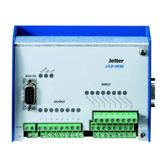
JX2-IO16 Mounting Dimensions Fig. 3: Front View - JX2-IO16 Fig. 4: Side View - JX2-IO16 Jetter AG... - Page 24 3 Mounting Dimensions JetWeb Fig. 5: Top View JX2-IO16 Jetter AG...
-
Page 25: Operating Conditions
JX2-IO16 Operating Conditions Operating Parameters: Power Rating Parameter Value Reference Power Rating DC 24 V (DC 20 V ... 30 V) Residual ripple: <= 5 % SELV power supply Power consumption: max. 5.775 Duration of voltage dips ≤ 10 ms... - Page 26 Frequency 30 - 230 MHz, DIN EN 50081-1 limit 30 dB (µV/m) at 10 m DIN EN 55011 distance DIN EN 50081-2 frequency band 230 - 1,000 MHz, limit 37 dB (µV/m) at 10 m distance (class B) Jetter AG...
- Page 27 JX2-IO16 Operating Parameters (EMC) - Immunity to Interference of Housing Parameter Value Reference Magnetic Field with 50 Hz, 60 Hz DIN EN 61000-6-2 Mains Frequency 30 A/m DIN EN 61000-4-8 RF Field, amplitude- Frequency band 27 - 1000 MHz DIN EN 61131-2...
- Page 28 DIN EN 61000-4-6 AM 80 % with 1 kHz Source impedance 150 Ohm Criterion A Burst (fast transients) Test voltage 2 kV DIN EN 61131-2 tr/tn 5/50 ns DIN EN 61000-6-2 Repetition rate 5 kHz DIN EN 61000-4-4 Criterion A Jetter AG...
-
Page 29: Technical Data
JX2-IO16 5.1 General Information Technical Data General Information Technical Data - General Module Code Rated voltage of logic circuit DC 24 V, max. ripple 5% Operating voltage range of logic DC 20 .. 30 V circuit and sensor supply ≤ 40 mA No-load current of logic circuit at X10.0,05A.DC24V (without other... -
Page 30: Digital Inputs
Minimum pulse length (high or low 250 µs pulse) Maximum counting frequency at 50 2 kHz % duty cycle Dual-channel counter Quantity 1 (via inputs 5 - 6, DC 24 V) Edge evaluation Quadruple evaluation Max. counting frequency 1 kHz Jetter AG... - Page 31 JX2-IO16 5.2 Digital Inputs U(V) 1 state Undefined 0 state I(mA) Fig. 6: Digital Inputs - Current voltage characteristic Jetter AG...
-
Page 32: Digital Outputs
Signal voltage ON Typ. V - 1.5 V supply Output Current Max. 0.5 A per output Total output power 96 W Electrical isolation None Protective circuit Short circuit, undervoltage, overtemperature Protection against inductive loads Principle of Operation Non-latching Jetter AG... -
Page 33: Installation Guide
JX2-IO16 module. Please check the shipment for completeness. Choose the place of the DIN rail for mounting the JX2-IO16 module and, if necessary, other expansion modules, such as JX-SIO, and JX2-..., in your electric cabinet. -
Page 34: Notes On Safety As Regards The Installation
Installation Danger resulting from electric shock! If the JX2-IO16 module is not isolated from the mains, for example during installation, maintenance, and repair, you can get an electric shock. Please observe the following precautions in order to avoid injuries such as... -
Page 35: Notes On Safety As Regards Commissioning
Notes on Safety as regards Commissioning Danger resulting from electric shock! If the JX2-IO16 module is not isolated from the mains, for example during commissioning, you can get an electric shock. Please observe the following precautions in order to avoid injuries such as... -
Page 36: General Information
JetWeb General Information Please note that in the module array of the controller the JX2-IO16 module appears as 1 module, though it performs the functions of 2 modules. The JX2- IO16 module is to be regarded as one combined JX2-PS1, JX2-OD8, and JX2-ID8 module. -
Page 37: Sample Circuitry
JX2-IO16 6.5 Sample Circuitry Sample Circuitry BUS IN INPUT OUTPUT POWER 0,05A 4A Fig. 7: JX2-IO16 Module: Sample circuitry Jetter AG... -
Page 38: Power Supply
5.1 "General Information", page 29. Attention! – The JX2-IO16 module is NOT protected against polarity reversal. – The maximum supply voltage must not exceed DC 30 V since a higher supply voltage may cause damages to the JX2-IO16 module. -
Page 39: Description Of Connections
JX2-IO16 6.6 Power Supply 6.6.2 Description of Connections Terminal Specifications • Double-level terminal block COMBICON 5.08. • Cable cross-sectional area: 0.25 - 2.5 mm • Torque (for input plug screws): 0.5 .. 0.6 Nm • The maximum stripping length for input lines is 7 mm •... -
Page 40: Description Of The Leds
6 Installation Guide JetWeb 6.6.3 Description of the LEDs BUS IN Fig. 9: Power LED LEDs: Power Supply Designation Colour Function POWER green External voltage supply of the digital outputs is provided. Jetter AG... -
Page 41: Digital Inputs
Fig. 10: Digital Inputs 6.7.1 Important information Apply a maximum voltage of 28.8 volt to the digital inputs of the JX2-IO16 module. This will prevent the JX2-IO16 module and the sensor, e.g. an inductive limit switch, from being destroyed. Caution Make sure that digital input modules are disconnected from the power supply before inserting or removing them. -
Page 42: Description Of Connections
4 / S Digital input # 4 5 / S Digital input # 5 6 / S Digital input # 6 7 / S Digital input # 7 8 / S Digital input # 8 1 - 8 / 0V Jetter AG... -
Page 43: Single-Channel Counter
JX2-IO16 6.7 Digital Inputs 6.7.3 Single-channel counter The 4 single-channels are connected as follows: Pin assignment of 24-pin three-level terminal blocks View Signal 5 - 8 / DC 24V Sensor power supply DC 24 V 5 / S Single-channel counter - Input # 5... -
Page 44: Dual-Channel Counter
The shield is to be connected to a separate grounding bar in close vincinity to the input terminals. For more information refer to Fig. 12. INPUT Fig. 12: Connecting an incremental encoder Jetter AG... -
Page 45: Description Of The Leds
JX2-IO16 6.7 Digital Inputs 6.7.5 Description of the LEDs INPUT Fig. 13: LEDs of the Digital Inputs LEDs of Digital Inputs Designation Colour Function INPUT X21 1 ... 8 yellow Digital input 1 through 8 Signal voltage ON OFF: Signal voltage OFF... -
Page 46: Digital Outputs
When removing or inserting the module, the supply lines as well as the signal lines must be de-energised. Otherwise the JX2- IO16 module will be destroyed. Caution A digital output may directly (without additional load) be connected to a digital input. Note Jetter AG... - Page 47 • If application of voltage cannot be avoided (for example, for testing inputs/ outputs with the JX2-IO16 module wired in an electric cabinet), the voltage has to be applied to the output drivers of the module before-hand. Otherwise the output drivers will be destroyed.
-
Page 48: Description Of Connections
Pin Assignment of 16-pin Double-Level Terminal Blocks View Signal Digital Output # 1 Digital Output # 2 Digital Output # 3 Digital Output # 4 Digital Output # 5 Digital Output # 6 Digital Output # 7 Digital Output # 8 Jetter AG... -
Page 49: Emergency Stop Circuit Of Outputs
JX2-IO16 6.8 Digital Outputs 6.8.3 Emergency Stop Circuit of Outputs Fig. 15: Example: Emergency Stop Circuit of Outputs Note! Once the Emergency Stop button is pressed, all outputs are set to 0 V. However, the logic circuit remains active, e.g. for error scanning. -
Page 50: Description Of The Leds
Signal voltage ON OFF: Signal voltage OFF Collective error message Overload, short circuit, overtemperature of one or more outputs. An error condition can be polled via controller. POWER green External voltage supply of the digital outputs is provided. Jetter AG... -
Page 51: System Bus
JX2-IO16 6.9 System Bus System Bus BUS IN INPUT OUTPUT POWER 0,05A 4A Fig. 17: System bus 6.9.1 Description of Connections Specification of Connectors On the controller side • 9-pin male SUB-D connector in metallized housing (quality grade 3). •... - Page 52 The maximum cable length depends on the baud rate used and the number of modules connected to the bus. • When calculating the maximum line length, please take into account that each module connected to the bus reduces the cable length by approx. 1 m. Jetter AG...
-
Page 53: Ordering Information
Signal CMODE0 CMODE1 TERM (not connected) Unassigned Unassigned Do not connect 6.9.2 Ordering Information The system bus cable can be purchased from Jetter AG in various lengths. For more information refer to chapter 2.3 "Ordering Information", page 20. Jetter AG... -
Page 54: Connecting Jx2-I/O Modules
6.10 Connecting JX2-I/O Modules Three more JX2-IO modules can directly be connected to the JX2-IO16 module. This configuration does not require a system bus cable or external power supply. For more than 3 JX2-IO modules a JX2-PS1 power supply module is required. - Page 55 JX2-IO16 6.11 Status LEDs Once the internal logic circuit has been energized, the booting sequence of the JX2- IO16 module is activated. The status of the booting sequence is displayed through the LEDs ERR and RUN. For more information on the status please refer to the...
- Page 56 6 Installation Guide JetWeb Jetter AG...
-
Page 57: Software Programming
JX2-IO16 7.1 Addressing Digital Inputs and Outputs Software Programming Addressing Digital Inputs and Outputs The address is made up of the location of the module and the number of the respective input or output. Addressing with JC-24x / NANO-A/B/C/D controllers:... - Page 58 Module no. 1 is assigned to the basic controller. Starting from there, the module numbers are being counted left to right. Basically, the granularity is 16. That means, for example, that a JX2-IO16 module occupies 16 logical outputs, despite it provides only 8 physical ones.
-
Page 59: Register Interface
JX2-IO16 7.2 Register Interface Example2: Configuration consisting of one JX2-SV1 System consisting of a JC-24x, one JX2-IO16 and one digital output module JX2- OD8: Basic Servo Input I/O Module controller module module JX2-IO16 JC-24x JX2-SV1 JX2-ID8 Module # 1 Module # 2... - Page 60 Register number: 4cm0 3xxz Meaning: Register number: 0...9 IO module number - 2 System bus module area: 03 System bus number: 1...2 Module board number: 1...3 Area number: 4 For more information refer to the manual on the JC-800 controller. Jetter AG...
-
Page 61: Addressing A Register Array
7.2.2 Addressing a Register Array The register array is used to parameterize JX2-IO16 functions and to read out additional diagnostic information. For this purpose, the index of the register array element is entered into register 8 "Register Array: Index". Register 9 "Register Array: Value"... - Page 62 Value after reset Register 3xx9: Register Array: Value Function Description Read Present value of the register array element Write New value of the register array element Value range Depending from register array element Value after reset Version number (Index 1) Jetter AG...
-
Page 63: Status And Control Functions
JX2-IO16 Status and Control Functions Register 3xx0 "Status / Controller" is available for status and control functions. Register 3xx0: Status / Controller Function Description Read Present module status Write Setting a new module mode, only bits 8 - 11 Value range... - Page 64 Pulse stretching - Input # 4 Bit 20: Pulse stretching - Input # 5 Bit 21: Pulse stretching - Input # 6 Bit 22: Pulse stretching - Input # 7 Bit 23: Pulse stretching - Input # 8 Jetter AG...
- Page 65 Output initialization Initialization of digital outputs in case of a warm restart (re-initialization of the JX2-IO16 module via controller without de-energizing and re- energizing the JX2-IO16 module). This function immediately becomes effective. See also chapter 12 "Diagnostic and Administrative Functions", page 93.
- Page 66 See chapter 11 "Counter Function", page 83. 0 = Inputs 5 - 6 are used as single-channel counters 1 = Inputs 5 - 6 are used as dual-channel counters with quadruple evaluation Value following reset: 0 Bit 11: Reserved Jetter AG...
-
Page 67: Fast Inputs - Software Filter
All digital inputs are provided with an input delay feature. The input signal is recognized by the JX2-IO16 module once the delay time has elapsed. The delay time for inputs 1 - 4 is preset (hardware filter); for more information refer to chapter "Technical Data of Digital Inputs", page 30. - Page 68 9 Fast inputs - Software filter JetWeb Jetter AG...
-
Page 69: Pulse Stretching
JX2-IO16 10.1 Overview of Registers Pulse stretching 10.1 Overview of Registers Register Name Brief Description General: 3xx0 Status / Controller Pulse stretching status, Page 63 3xx3 Present input state Actual input state at the input terminal, Page 78 3xx8 29... - Page 70 Fig. 19: Generating the pulse stretching The pulse evaluation circuit checks for each input whether the pulse stretching condition is fulfilled. If the condition is fulfilled, the JX2-IO16 module activates the pulse stretching for each input separately. That is, the input signal is stretched, for example, starting from its rising edge.
- Page 71 In this case, the length of the actual input pulse determines the length of the stretched input pulse. Once pulse stretching is deactivated, the actual input state is displayed. The JX2-IO16 module provides two types of pulse stretching: • Manual pulse stretching •...
-
Page 72: Manual Pulse Stretching
3xx1 and the pulse stretching state of the input is immediately polled. For more information refer to Example5: "Manual pulse stretching - Variant 1". In order to always poll the actual input state at the input terminal of the JX2-IO16 module immediately after a reset, register 3xx3 "Present input state" has to be read out. - Page 73 JX2-IO16 10.3 Manual pulse stretching Example5: Manual pulse stretching - Variant 1 Loop with input number polling Excerpt from the program REGISTER_LOAD (3008, 30) Selecting the register array element 30 -> Edge/ State BIT_CLEAR (3009, 0) // Selecting "Edge" REGISTER_LOAD (3008, 29) Selecting register array element 29 ->...
-
Page 74: Automatic Pulse Stretching
31 - 38. Examples On the first JX2-IO16 module located after the controller, input signal of input 1 is to be stretched for 10 ms automatically when the edge is rising. Example7: Automatic pulse stretching - Variant 1... - Page 75 JX2-IO16 10.4 Automatic pulse stretching WHEN IN 201 THEN Waiting until first rising edge is sensed // Doing anything WHEN -IN 201 THEN Waiting until pulse stretching duration is reset GOTO l_Check_Input_1 // End of loop Example8: Automatische Impulsverlängerung - Variante 2 Schleife mit Abfrage einer aktiven Impulsverlängerung...
-
Page 76: Register Description
Input # 1 Bit 1: Input # 2 Bit 2: Input # 3 Bit 3: Input # 4 Bit 4: Input # 5 Bit 5: Input # 6 Bit 6: Input # 7 Bit 7: Input # 8 Jetter AG... - Page 77 JX2-IO16 10.5 Register Description Register 3xx2: Manual pulse stretching - Resetting Function Description Read Inputs for manual pulse stretching disabled and reset last Write Disabling and resetting inputs for manual pulse stretching with immediate effect Value range Bit-coded, 8 bits Value after reset Through this register pulse stretching of inputs can be disabled again.
- Page 78 Input # 7 Bit 7: Input # 8 The input state of the JX2-IO16 module is normally read out through the input numbers of the controller. When using manual pulse stretching on the JX2-IO16 module, register 3xx3 has to be used for reading the present input state.
- Page 79 JX2-IO16 10.5 Register Description Register 3xx8 = 29 Register 3xx9: Edge evaluation - Polarity Function Description Read Present polarity Write New polarity (will immediately become effective) Value range Bit-coded, 8 bits Value after reset 0b 11111111 Polarity is always set together with register array element 30 "Edge evaluation - Edge / State".
- Page 80 Input # 1 Bit 1: Input # 2 Bit 2: Input # 3 Bit 3: Input # 4 Bit 4: Input # 5 Bit 5: Input # 6 Bit 6: Input # 7 Bit 7: Input # 8 Jetter AG...
- Page 81 JX2-IO16 10.5 Register Description Register 3xx8 = 31 ... 38 Register 3xx9: Automatic pulse stretching - Pulse stretching duration - Input 1 ... 8 Function Description Read Present pulse stretching duration Write New pulse stretching duration (will become effective only on completion of the active pulse stretching process).
- Page 82 10 Pulse stretching JetWeb Jetter AG...
-
Page 83: Counter Function
JX2-IO16 11.1 Overview of Registers Counter Function 11.1 Overview of Registers Register Name Brief Description General: 3xx8 20 Configuration of an input as counter 3xx9 Counter configuration input, Page 91 3xx8 45 - 48 Software filter for inputs 5 ... 8, Page 67... -
Page 84: Single-Channel Counter
Configuring the input as counter in register array element 20 "Counter configuration" reduces the system bus communication, because the changed input status will no longer be sent automatically from the JX2-IO16 module to the controller. The update frequency for the input state in the controller now depends from the cycle time the controller uses to update the input state of the JX2-IO16 module. - Page 85 JX2-IO16 11.3 Single-channel counter Using manual pulse stretching, incrementation of the single-channel counter reading can be stopped, or re-started through the application program. When doing so, it has to be taken into account that the write process for enabling and disabling manual pulse stretching via register 3xx1 and 3xx2 requires a short turnaround time, which is not exactly quantifiable.
- Page 86 Example Example 9: Single-channel counter Pulses are to be counted via input 8 of a JX2-IO16 module which is connected as second IO module. Once a certain number of pulses is reached, a stop signal is to be output via output 1.
-
Page 87: Dual-Channel Counter
JX2-IO16 11.4 Dual-channel counter 11.4 Dual-channel counter Logic processing Signal 5 & 6 at the input terminal No processing Dual- Software channel filter counter Fig. 27: Evaluating a dual-channel counter signal The dual-channel counter signal is read in via input 5 (K1) and input 6 (K2). The shift between these two signals is 90°. - Page 88 Example Example 10: Dual-channel counter Position sensing is to be carried out using the dual-channel counter of a JX2-IO16 module which is connected as second IO module. Once a certain position is reached, a stop signal is to be output via output 1.
-
Page 89: Frequency Measurement
5. The JX2-IO16 module measures counting pulses which are sensed during an adjustable time base. Once the time base has elapsed, the JX2-IO16 module subtracts the current reading of the dual-channel counter or the single-channel counter of input 5 from the reading... -
Page 90: Register Description
This function is always active, irrespective of the fact whether input 5 is used as single-channel or dual-channel counter. It is of special interest when using the dual- channel counter. The frequency is calculated in the application program using the following formula: Jetter AG... - Page 91 JX2-IO16 11.6 Register Description Counter reading difference Frequency (Hz) ----------------------------------------------------------------------------------------------------------------------------------- - Time base for counter reading difference x 10 ms Register 3xx8 = 9 Register 3xx9: Timebase for counter reading difference - Input 5 Function Description Read Present time base...
- Page 92 Configuring the input as counter in register array element 20 "Counter configuration" reduces the system bus communication, because the changed input status will no longer be sent automatically from the JX2-IO16 module to the controller. The update frequency for the input state in the controller now depends from the cycle time the controller uses to update the input state of the JX2-IO16 module.
-
Page 93: Diagnostic And Administrative Functions
12.1.1 Error in System bus communication - Timeout A timeout exists if the JX2-IO16 module for a specified period does not receive monitoring messages from the controller via system bus. The timeout threshold is set using the two register array elements 4 "Communication - Time base", and 5 "Communication - Multiplicator". -
Page 94: System Bus Communication Error - Data Buffer Overflow
Along with this error, the controller may display a timeout for the JX2-IO16 module. Possible causes for data buffer overflow • This error message indicates an overload of the system bus or the JX2-IO16 module. Troubleshooting •... -
Page 95: 12.1.3 Error In The Output Circuit
Eliminate short circuit at one or several outputs • Ensure a stable power supply Error acknowledgement • This error message will automatically be deleted by the JX2-IO16 module once the error signal from the output circuit is canceled. Jetter AG... -
Page 96: Response Of Digital Outputs To Timeout
The controller saves the last output state of the JX2-IO16 module before the timeout has occurred. If the output state has changed as a result of an error status on the JX2-IO16 module, the output state, which has been saved by the controller for the JX2-IO16, is no longer applicable. - Page 97 Controller". For more information refer to chapter 8 "Status and Control Functions", page 63. During re-initialization the output state saved by the controller for the JX2-IO16 module is also set to the output state of the JX2-IO16. For more information refer to Fig. 30.
- Page 98 Initialization 1 The module is re-initalized through the CPU (without disabling the module) Transfer Initialization 2 The module is re- initialized by disabling and enabling it Initialization to 0 Fig. 30: Ouput state response when restarting the module Jetter AG...
-
Page 99: Overview Of Registers
When errors have occurred, the register array element is zeroed by entering the value 0. At the same time, bit 15 in register "Status / Controller" is also reset and the ERROR LED is switched off. Errors which are automatically deleted by the JX2-IO16 module are marked with an *. Jetter AG... - Page 100 Data buffer overflow indicates that the JX2-IO16 has received more system bus requests than the data buffer memory can hold. Along with this error, the controller may display a timeout for the JX2-IO16 module. ATTENTION: This error message indicates an overload of the system bus or the JX2- IO16 module.
- Page 101 JX2-IO16 12.3 Overview of Registers Together with register array element 5 this register array element is for setting the timeout threshold for system bus communication. The timout threshold is calculated using the following formula: Timeout threshold = Time base (register array element 4)* Multiplicator (register array element 5).
- Page 102 For an error definition please refer to description of register array element 2 "Error", Page 99, and chapter 12.1 "Error Diagnosis", page 93. Register 3xx8 = 50 Register 3xx9: Outputs - Error mode Function Description Read Present error mode Write New error mode Value range Bit-coded, 8 bits Value after reset Jetter AG...
- Page 103 JX2-IO16 12.3 Overview of Registers Through the error mode register the response to a system bus communication timeout can be defined for each output separately: Maintaining the actual status Setting the error status Meaning of the individual bits: Bit 0:...
- Page 104 12 Diagnostic and Administrative Functions JetWeb Meaning of the individual bits: Bit 6: Output 7 Bit 7: Output 8 Jetter AG...
- Page 105 JX2-IO16 Appendix Appendices Jetter AG...
- Page 106 Appendices JetWeb Jetter AG...
-
Page 107: Appendix A: Recent Revisions
JX2-IO16 Appendix Appendix A: Recent Revisions Appendices List Chapter Comment Revised Added Deleted Various Various changes to the wording Installation Description of status LEDs has been revised Pulse Stretching Description of manual pulse stretching: "Enabling is displayed in register through bits 0 .. 8"... -
Page 108: Appendix B: Overview Of Registers
JetWeb Appendix B: Overview of Registers For communication with the CPU, 10 registers are provided by the JX2-IO16 module. In addition, a register array is available, which can be addressed via register 8, and register 9. When doing so, register 8 indicates the index of the register array element, and register 9 contains the value of the element. - Page 109 JX2-IO16 Appendix Register Name 1) Value Range Number 2) Default value 3) Cross Reference With a warm restart, outputs are set to 0. With a warm restart, outputs maintain the last state. Bit 10: Counter configuration Inputs 5 - 6 are used as single-...
- Page 110 Input # 7 Bit 7: Input # 8 3xx4 - Reserved 3xx5 3xx6 Single-channel counter - 1) -8.388.608 ... 8.388.607 Counter reading of input 5 2) 0 Dual-channel counter - 3) Page 90 Counter reading (inputs 5 and 6) Jetter AG...
- Page 111 JX2-IO16 Appendix Register Name 1) Value Range Number 2) Default value 3) Cross Reference 3xx7 Single-channel counter - 1) -8.388.608 ... 8.388.607 Counter reading of input 2) 0 3) Page 90 3xx8 Register Array: Index 1) 1...51 2) 1 3) Page 62...
- Page 112 1) bit-oriented, 8 bits 2) Error code saved last but seven 3) Page 102 Refer to bit definitions with index 10 Error history - Entry 8 1) bit-oriented, 8 bits 2) Error code saved last but eight 3) Page 102 Jetter AG...
- Page 113 JX2-IO16 Appendix Index Name 1) Value Range 2) Default value 3) Cross Reference Refer to bit definitions with index 10 Error history - Entry 9 1) bit-oriented, 8 bits 2) Oldest error code saved 3) Page 102 Refer to bit definitions with index 10...
- Page 114 1) 0 ... 255 ms stretching - 2) 0 (deactivated) Stretching period - Input # 6 3) Page 81 Automatic pulse 1) 0 ... 255 ms stretching - 2) 0 (deactivated) Stretching period - Input # 7 3) Page 81 Jetter AG...
- Page 115 JX2-IO16 Appendix Index Name 1) Value Range 2) Default value 3) Cross Reference Automatic pulse 1) 0 ... 255 ms stretching - 2) 0 (deactivated) Stretching period - Input # 8 3) Page 81 39 - 44 Reserved Software filter - Delay 1) 0 ...
- Page 116 3) Cross Reference Bit 1: Input # 2 Bit 2: Input # 3 Bit 3: Input # 4 Bit 4: Input # 5 Bit 5: Input # 6 Bit 6: Input # 7 Bit 7: Input # 8 Jetter AG...
-
Page 117: Appendix C: Glossary
The Jetter system bus is a system-bus system with a cable length of max. 200 m, and a data transmission rate of 1 Mbit/s. In addition to this, the Jetter system bus is highly immune to interferences. Therefore, the Jetter system bus is suited to realise field bus applications in a limited space. - Page 118 "rise time of a pulse / total duration of a pulse" Verband deutscher Elektrotechniker e.V. = Association of German Electrical Engineers Width Units: Ampere Dezibel Gram Hertz Meter Millimeter (1 mm = 10 Minute Second Volt Watt Jetter AG...
-
Page 119: Appendix D: List Of Illustrations
Fig. 1: Shielding of SUB-D connectors in conformity with EMC standards. Fig. 2: Shielding of screw terminals in conformity with the EMC standards. Fig. 3: Front View - JX2-IO16 Fig. 4: Side View - JX2-IO16 Fig. 5: Top View JX2-IO16 Fig. -
Page 120: Appendix E: Index Of Examples
Example4: Addressing a Register Array Example5: Manual pulse stretching - Variant 1 Example6: Manual pulse stretching - Variant 2 Example7: Automatic pulse stretching - Variant 1 Example8: Automatische Impulsverlängerung - Variante 2 Example9: Single-channel counter Example10: Dual-channel counter Jetter AG... -
Page 121: Appendix F: Index
JX2-IO16 Appendix Appendix F: Index Addressing LEDs Digital inputs and outputs Digital Inputs Registers Digital Outputs Power Supply Status Booting sequence displayed by LEDs Maintenance Malfunction Malfunctions Connection Modifications Dig. outputs Digital inputs Dual-channel counter Power Supply Noise immunity Single-channel counter... - Page 122 Appendices JetWeb Safety Instructions as to Technical Data Commissioning Dig. outputs Installation Digital inputs General Information System Bus Cable Cable confection # 530 Specs System Requirements Usage as agreed upon Usage Other Than Agreed Upon User Jetter AG...
- Page 123 JX2-IO16 Appendix Jetter AG...
- Page 124 Hotline: +49 7141 2550-444 Internet: http://www.jetter.de E-Mail: sales@jetter.de Jetter Subsidiaries Jetter Asia Pte. Ltd. Jetter (Schweiz) AG Jetter USA Inc. 32 Ang Mo Kio Industrial Park 2 Münchwilerstraße 19 165 Ken Mar Industrial Parkway #05-02 Sing Industrial Complex CH-9554 Tägerschen...
Need help?
Do you have a question about the JX2-IO16 and is the answer not in the manual?
Questions and answers