
Related Manuals for GEM 710


Summary of Contents for GEM 710
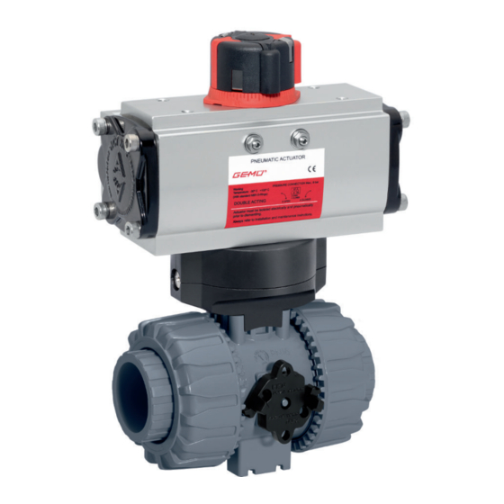
- Page 1 GEMÜ 710 Pneumatically operated ball valve Operating instructions further information webcode: GW-710...
- Page 2 All rights including copyrights or industrial property rights are expressly reserved. Keep the document for future reference. © GEMÜ Gebr. Müller Apparatebau GmbH & Co. KG 23.11.2020 GEMÜ 710 2 / 44 www.gemu-group.com...
-
Page 3: Table Of Contents
EC (Machinery Directive) ........... 40 20 Declaration of conformity according to 2014/68/EU (Pressure Equipment Directive) ......... 41 21 EU Declaration of conformity 2-way ball valve ... 42 22 EU Declaration of conformity 3-way ball valve ... 43 www.gemu-group.com 3 / 44 GEMÜ 710... -
Page 4: General Information
Symbol Meaning Danger of explosion 1.3 Definition of terms Working medium The medium that flows through the GEMÜ product. Corrosive chemicals! Control medium The medium whose increasing or decreasing pressure causes the GEMÜ product to be actuated and operated. Hot plant components! Control function The possible actuation functions of the GEMÜ... -
Page 5: Product Description
15. Consult the nearest GEMÜ sales office. Ball valve seat seals PTFE 3.2 Description The 2/2 and/or 3/2-way GEMÜ 710 plastic ball valve has a pneumatic actuator, which can either be made from alu- minium or plastic. The seat seal is made from PTFE and the O-ring seals can be made from either EPDM or FKM. -
Page 6: Correct Use
The product is controlled via a pneumatic actuator. tomer OPEN ● Use the product in accordance with the technical data. Delivery condition Code L Optional port positions, can be user adjusted Code 6 GEMÜ 710 6 / 44 www.gemu-group.com... -
Page 7: Actuator Assignment For 2/2-Way Valves
DN 50 DN 65 1) Actuator version Code 0: GEMÜ actuator, pneumatic, size 0, piston diameter 50 mm Code 1: GEMÜ actuator, pneumatic, size 1, piston diameter 70 mm 6 Actuator assignment for multi-port valves Please contact GEMÜ for the actuator assignment of multi-port valves. -
Page 8: Order Data
Ball valve, plastic, pneumatically operated Double acting (DA) 2 DN Code 8 Actuator version Code DN 10 Actuator GEMÜ ADA and ASR DN 15 Actuator, pneumatic, single acting, clockwise rota- AU02FN tion, spring closing, DN 20 ASR0020US08F03/05 S09 DN 25... - Page 9 T-port, standard end position "Closed", connection 1 and 3 open Actuator GEMÜ 9415 T-port, end position "Open", connection 1 and 3 GEMÜ actuator, pneumatic, size 0, piston diameter open, 50 mm T-port, end position "Closed", connection 1 and 2 GEMÜ actuator, pneumatic, size 1, piston diameter...
-
Page 10: Technical Data
Data for extended temperature ranges on request. Please note that the ambient temperature and media temper- ature generate a combined temperature at the valve body which must not exceed the above values. Control pressure: 2 to 8 bar (depending on version and/or control function) GEMÜ 710 10 / 44 www.gemu-group.com... - Page 11 90 100 Opening [%] For 0°- 90° control range, linear control characteristic between port position and percentage flow rate. NOTE: Ball configuration (R) cannot be retrofitted to standard 2/2-way bodies at a later date. www.gemu-group.com 11 / 44 GEMÜ 710...
- Page 12 7725 11141 Weight in g 1) Ball valve material Code 1: PVC-U, grey Code 2: PVC-C Code 4: ABS Code 5: PP-H, grey Code 20: PVDF Actuator GEMÜ DR/SC Type 0015U 0030U 0060U 0100U 0150U 0220U Weights in kg GEMÜ 710 12 / 44 www.gemu-group.com...
- Page 13 8 Technical data Weight: Actuator GEMÜ ADA/ASR Type 0020U 0040U 0080U 0130U 0200U Weights in kg Actuator GEMÜ 9415 Actuator 9415 Actuator size 0: Control function 1: 435 g Control function 3: 325 g Actuator size 1: Control function 1:...
-
Page 14: Dimensions
9 Dimensions 9 Dimensions 9.1 Actuator dimensions 9.1.1 GEMÜ ADA/ASR Typ 00010 - 4000U Typ 00010 - 1750U Typ 02100 - 4000U Typ 00010 - 0850U Typ 00010 - 4000U Typ 00010 - 4000U ØM Typ 01200 - 4000U 00010 76.0... - Page 15 9 Dimensions 9.1.2 GEMÜ DR/SC Type 0015U - 1200U Typ 0015U - 1200U Connector 4 Connector 2 Typ 2000U - 4000U Type 2000U - 4000U Connector 4 Connector 2 Typ 5000U Type 5000U Connector 4 Connector 2 Type 0015U 89.0 69.0...
- Page 16 F07 x 8.5 14.0 16.0 131.0 87.0 F07 x 9.0 F05 x 6.5 14.0 16.0 131.0 105.0 F07 x 9.0 F05 x 6.5 17.0 19.0 149.0 129.0 F07 x 9.0 F05 x 6.5 Dimensions in inch GEMÜ 710 16 / 44 www.gemu-group.com...
- Page 17 22.5 50.0 M6 x 10.0 70.0 M8 x 16.0 0200U 17.0 22.5 70.0 M8 x 16.0 102.0 M10 x 16.0 0300U 22.0 28.5 70.0 M8 x 16.0 102.0 M10 x 16.0 Dimensions in inch www.gemu-group.com 17 / 44 GEMÜ 710...
- Page 18 Code 4: Union end with flange EN 1092, PN 10, form B, face-to-face dimension FTF EN 558 series 1, ISO 5752, basic series 1 Code 39: Union end with flange ANSI Class 125/150 RF Code 78: Union end with insert (for IR butt welding) - DIN GEMÜ 710 18 / 44 www.gemu-group.com...
- Page 19 Code 33: Union end with inch insert - BS (socket) Code 3M: Union end with inch insert – ASTM (socket) Code 3T: Union end with JIS insert (socket) Code 7R: Union end with insert (Rp threaded socket) - DIN www.gemu-group.com 19 / 44 GEMÜ 710...
- Page 20 Code 4: Union end with flange EN 1092, PN 10, form B, face-to-face dimension FTF EN 558 series 1, ISO 5752, basic series 1 Code 39: Union end with flange ANSI Class 125/150 RF Code 3M: Union end with inch insert – ASTM (socket) GEMÜ 710 20 / 44 www.gemu-group.com...
- Page 21 Code 2: Union end with insert (solvent cement or weld socket) - DIN Code 33: Union end with inch insert - BS (socket) Code 7R: Union end with insert (Rp threaded socket) - DIN www.gemu-group.com 21 / 44 GEMÜ 710...
- Page 22 Code 4: Union end with flange EN 1092, PN 10, form B, face-to-face dimension FTF EN 558 series 1, ISO 5752, basic series 1 Code 39: Union end with flange ANSI Class 125/150 RF Code 78: Union end with insert (for IR butt welding) - DIN Code 7R: Union end with insert (Rp threaded socket) - DIN GEMÜ 710 22 / 44 www.gemu-group.com...
- Page 23 Code 4: Union end with flange EN 1092, PN 10, form B, face-to-face dimension FTF EN 558 series 1, ISO 5752, basic series 1 Code 39: Union end with flange ANSI Class 125/150 RF Code 78: Union end with insert (for IR butt welding) - DIN www.gemu-group.com 23 / 44 GEMÜ 710...
- Page 24 Code 3M: Union end with inch insert – ASTM (socket) Code 3T: Union end with JIS insert (socket) Code 78: Union end with insert (for IR butt welding) - DIN Code 7R: Union end with insert (Rp threaded socket) - DIN GEMÜ 710 24 / 44 www.gemu-group.com...
- Page 25 179.0 190.5 190.6 266.5 267.0 Dimensions in inch 1) Connection type Code 2: Union end with insert (solvent cement or weld socket) - DIN Code 3M: Union end with inch insert – ASTM (socket) www.gemu-group.com 25 / 44 GEMÜ 710...
- Page 26 Code 2: Union end with insert (solvent cement or weld socket) - DIN Code 78: Union end with insert (for IR butt welding) - DIN Code 7R: Union end with insert (Rp threaded socket) - DIN GEMÜ 710 26 / 44 www.gemu-group.com...
-
Page 27: Manufacturer's Information
Provide precautionary measures against exceeding the ● 4. Do not store solvents, chemicals, acids, fuels or similar maximum permitted pressures caused by pressure fluids in the same room as GEMÜ products and their spare surges (water hammer). parts. CAUTION Use as step. -
Page 28: Installation With Inserts For Solvent Cementing
7. Push the piping 5 into the insert 4. 8. Screw the union nut 1 to the ball valve body 2 again. 9. Connect the other connections of the ball valve body 2 with the piping 5 in the same manner. GEMÜ 710 28 / 44 www.gemu-group.com... -
Page 29: Installation With Inserts For Welding
7. Screw the insert 4 into the piping 5. 8. Screw the union nut 1 to the ball valve body 2 again. 9. Connect the other connections of the ball valve body 2 with the piping 5 in the same manner. www.gemu-group.com 29 / 44 GEMÜ 710... -
Page 30: Installation With Flanged Connection
7. Connect the valve flange and the piping flange using ap- propriate sealing materials and matching bolting. 8. Use all flange holes. 9. Tighten the bolts diagonally. 10. Re-attach or reactivate all safety and protective devices. GEMÜ 710 30 / 44 www.gemu-group.com... -
Page 31: Commissioning
Setting the 0° end position (±5°): 13. Move the actuator to the open position. 14. Loosen the lock nut 3. 15. Set the end position via screw 4. 16. Tighten the lock nut 3. www.gemu-group.com 31 / 44 GEMÜ 710... - Page 32 9. Release the latch 1 of the threaded connection locking device. ð The tooth of the threaded connection locking device engages with the teeth of the union nut 2 and fixes it in place. GEMÜ 710 32 / 44 www.gemu-group.com...
-
Page 33: Troubleshooting
Check installation of ball valve body in piping Ball valve body leaking Ball valve body faulty Check ball valve body for potential dam- age and replace if necessary No flow Ball incorrectly adjusted Turn ball to the correct position www.gemu-group.com 33 / 44 GEMÜ 710... -
Page 34: Inspection And Maintenance
3. Shut off plant or plant component. 4. Secure plant or plant component against recommission- ing. 5. Depressurize the plant or plant component. 6. Actuate GEMÜ products which are always in the same po- sition four times a year. GEMÜ 710 34 / 44... - Page 35 Control function 1, 2 and 3: On request Actuator size 0 (DN15 + Actuator size 1 / 2 (DN 25 – 50) Mounting kit DN 10 – 25 710 15SMK (88353335) DN20 710 20SMK (88351044) DN25 710 25SMK (88353770) DN32 710 32SMK (88353388)
- Page 36 Control function 3: Actuator size 1 / 2 (DN 65), actuator size 3 (DN 80 - 100) Mounting kit DN 65 - 100 710 100SMK (88441143) XX - corresponds to nominal sizes DN 65 – 100. GEMÜ 710 36 / 44 www.gemu-group.com...
- Page 37 Control function 1, 2 and 3: Actuator size 0 (DN 15 + On request Actuator size 1 / 2 (DN 25 - Mounting kit DN 10 - 25 710 15SMK (88353335) DN 20 710 20SMK (88351044) DN 25 710 25SMK (88353770) DN 32...
- Page 38 13. Carefully press out the ball 6 (taking care not to scratch the ball). 14. Press the spindle(s) 4 (21) into the ball valve body and re- move. 15. Refit all parts in the reverse order. GEMÜ 710 38 / 44 www.gemu-group.com...
-
Page 39: Cleaning The Product
Returned goods can be processed only when this note is completed. If no return delivery note is included with the product, GEMÜ cannot process credits or repair work but will dispose of the goods at the operator's expense. -
Page 40: Declaration Of Incorporation According To 2006/42/Ec (Machinery Directive)
19 Declaration of Incorporation according to 2006/42/EC (Machinery Directive) Declaration of Incorporation according to the EC Machinery Directive 2006/42/EC, Annex II, 1.B for partly completed machinery GEMÜ Gebr. Müller Apparatebau GmbH & Co. KG Fritz-Müller-Straße 6-8 74653 Ingelfingen-Criesbach, Germany declare that the following product Make: GEMÜ... -
Page 41: Declaration Of Conformity According To 2014/68/Eu (Pressure Equipment Directive)
EN 1983, AD 2000 Note for products with a nominal size ≤ DN 25: The products are developed and produced according to GEMÜ process instructions and quality standards which comply with the requirements of ISO 9001 and ISO 14001. According to Article 4, Paragraph 3 of the Pressure Equipment Directive 2014/68/EU these products must not be identified by a CE-label. -
Page 42: Eu Declaration Of Conformity 2-Way Ball Valve
21 EU Declaration of conformity 2-way ball valve 21 EU Declaration of conformity 2-way ball valve The underlined type (VKD) corresponds to GEMÜ 710 (2-way ball valve) GEMÜ 710 42 / 44 www.gemu-group.com... -
Page 43: Eu Declaration Of Conformity 3-Way Ball Valve
22 EU Declaration of conformity 3-way ball valve 22 EU Declaration of conformity 3-way ball valve The underlined type (TKD) corresponds to GEMÜ 710 (3-way ball valve) www.gemu-group.com 43 / 44 GEMÜ 710... - Page 44 Subject to alteration GEMÜ Gebr. Müller Apparatebau GmbH & Co. KG *88593001* Fritz-Müller-Straße 6–8, 74653 Ingelfingen-Criesbach, Germany 11.2020 | 88593001 Phone +49 (0) 7940 1230 · info@gemue.de www.gemu-group.com...
Need help?
Do you have a question about the 710 and is the answer not in the manual?
Questions and answers