
Related Manuals for GEM 798


Summary of Contents for GEM 798
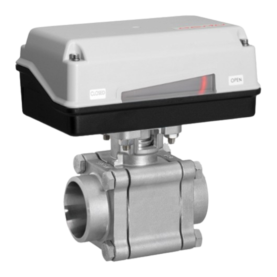
- Page 1 GEMÜ 798 Motorized high-pressure ball valve Operating instructions further information webcode: GW-798...
- Page 2 All rights including copyrights or industrial property rights are expressly reserved. Keep the document for future reference. © GEMÜ Gebr. Müller Apparatebau GmbH & Co. KG 20.02.2020 GEMÜ 798 2 / 51 www.gemu-group.com...
-
Page 3: Table Of Contents
Warning notes ............. 2 Safety information ............ 3 Product description ........... Construction ............Description ............Function ............... 4 GEMÜ CONEXO ............5 Correct use ............... 6 Order data ..............7 Technical data ............10 8 Dimensions ............... 16 Actuators ............. 16 Ball valve body ............. -
Page 4: General Information
Response(s) to tasks – Lists 1.3 Definition of terms Hot plant components! Working medium The medium that flows through the GEMÜ product. Risk of electric shock 1.4 Warning notes Wherever possible, warning notes are organised according to the following scheme: SIGNAL WORD... -
Page 5: Safety Information
3.2 Description turer first. The GEMÜ 798 3-piece 2/2-way metal ball valve is motorized. In cases of uncertainty: It has a plastic actuator housing. A manual override and an 15. Consult the nearest GEMÜ sales office. -
Page 6: Function
Installing the RFID chip The product is a motorized 2/2-way ball valve with a 3-piece body made of stainless steel. The GEMÜ 798 2/2-way ball In the corresponding design with CONEXO, this product has valve is designed for installation in piping systems. -
Page 7: Correct Use
● Use the product in accordance with the technical data. The product must not be exposed to pressure fluctuations. If the product is to be used with pressure fluctuations, please contact GEMÜ. www.gemu-group.com 7 / 51 GEMÜ 798... -
Page 8: Order Data
DIN 3202-5, S13 Spigot ASME BPE 10 Actuator version Code Spigot ISO 1127/EN 10357, series C GEMÜ actuator, motorized, size 1, operating time 1015 11 s, torque 15 Nm, Flange EN 1092, PN 40, form B, supply voltage B1, C1... - Page 9 8 Voltage/Frequency 12 VDC 9 Control module On/Off actuator, relay, not reversible 10 Actuator version 2070 GEMÜ actuator, motorized, size 2, operating time 15 s, torque 70 Nm, supply voltage C1 11 Type of design Without 12 CONEXO without 9 / 51 www.gemu-group.com...
-
Page 10: Technical Data
0 to 40 °C 7.3 Pressure Operating pressure: 0 to 137 bar The product must not be exposed to pressure fluctuations. If the product is to be used with pres- sure fluctuations, please contact GEMÜ. Pressure/temperature Reduced bore (code R) diagram: 2200 151.7... - Page 11 93.5 2½" 0.34 1.275 4.25 17.85 28.9 45.05 63.75 87.55 127.5 3" 0.425 2.125 11.9 21.25 55.25 77.35 108.8 140.3 4" 0.595 2.55 9.35 21.25 50.15 76.5 119.9 180.2 302.6 Kv values in m³/h 11 / 51 www.gemu-group.com GEMÜ 798...
- Page 12 0.595 2.975 15.3 29.75 76.5 114.8 174.3 263.5 4" 0.85 2.975 13.6 63.75 106.3 161.5 250.8 375.7 569.5 Kv values in m³/h 7.4 Product compliance Machinery Directive: 2006/42/EC EMC Directive: 2014/30/EU Low Voltage 2014/35/EU Directive: 12 / 51 GEMÜ 798 www.gemu-group.com...
- Page 13 2) Body configuration Code V: 2/2-way body, full bore Code R: 2/2-way body, reduced bore Actuator Actuator version 1015: Actuator version 3035: Actuator version 2070: Actuator version 4100: 11.6 Actuator version 4200: 11.6 Weights in kg 13 / 51 www.gemu-group.com GEMÜ 798...
- Page 14 (code C1) (code C4) (code G4) (code L4) code code (code O4) 1015 A0, AE 3035 A0, AE 2070 00, 0E, 0P 4100 00, 0E, 0P 4200 00, 0E, 0P Power consumption in W 14 / 51 GEMÜ 798 www.gemu-group.com...
- Page 15 (code C1) (code C4) (code G4) (code L4) code code (code O4) 1015 A0, AE 3035 A0, AE 2070 00, 0E, 0P 4100 00, 0E, 0P 4200 00, 0E, 0P Current data in A 15 / 51 www.gemu-group.com GEMÜ 798...
-
Page 16: Dimensions
Only with flanged connections the actuator is mounted across the piping 8.1.1 Actuator version 1015 * Standard with supply voltage code O4 Dimensions in mm 8.1.2 Actuator version 3035, 3055 Voltages 24 V 100.5 100 V - 250 V 124.5 Dimensions in mm 16 / 51 GEMÜ 798 www.gemu-group.com... - Page 17 8 Dimensions 8.1.3 Actuator version 2070 121,5 83,5 Dimensions in mm 8.1.4 Actuator version 4100, 4200 277,5 Dimensions in mm 17 / 51 www.gemu-group.com GEMÜ 798...
-
Page 18: Ball Valve Body
DIN ISO 5211 Actuator version Connection size Location spigot (code) (code) (code) 10XX / 20XX Ø5.5 10XX / 20XX 10XX / 20XX 10XX / 20XX 10XX / 20XX 3035 Dimensions in mm 8.2 Ball valve body 18 / 51 GEMÜ 798 www.gemu-group.com... - Page 19 2/2-way body, reduced bore (code R) ød øD 1/2" 24.5 12.6 21.7 3/4" 24.5 27.2 1" 31.4 1¼" 41.3 42.7 1½" 48.4 48.6 2" 56.3 60.5 2½" 71.4 76.3 3" 86.6 4" Dimensions in mm 19 / 51 www.gemu-group.com GEMÜ 798...
- Page 20 2“ NPT 127.3 56.3 2½" G 2½ 2½“ NPT 71.4 3" 3“ NPT 86.6 4" 4“ NPT Dimensions in mm 1) Connection type Code 1: Threaded socket DIN ISO 228 Code 31: Threaded socket NPT 20 / 51 GEMÜ 798 www.gemu-group.com...
- Page 21 2/2-way body, reduced bore (code R) ød ØD 1/2" 24.5 12.6 21.9 3/4" 72.5 24.5 27.3 1" 85.4 31.4 33.9 1¼" 105.3 41.3 42.8 1½" 48.4 48.9 2" 127.3 56.3 61.3 2½" 71.4 72.7 Dimensions in mm 21 / 51 www.gemu-group.com GEMÜ 798...
- Page 22 19.0 1" 41.3 161.5 22.2 25.4 1½" 56.3 182.2 34.9 38.1 2" 71.4 191.7 47.5 50.8 2½" 86.6 247.6 60.3 63.5 3" 99.0 266.8 73.0 76.2 4" 127.0 317.6 97.4 101.6 Dimensions in mm 22 / 51 GEMÜ 798 www.gemu-group.com...
- Page 23 31.4 20.0 26.9 1” 41.3 25.0 33.7 1¼” 48.4 32.0 42.4 1½” 56.3 38.0 48.3 2” 71.4 50.0 60.3 2½” 86.6 65.0 76.1 3” 99.0 80.0 88.9 4” 127.0 100.0 114.3 Dimensions in mm 23 / 51 www.gemu-group.com GEMÜ 798...
- Page 24 Side view X n x øy 2/2-way body, full bore (code V) ød øD øg øK øy 1/2" 24.5 3/4" 31.4 1" 41.3 1¼" 48.4 1½" 56.3 2" 71.4 2½" 86.6 3" 4" Dimensions in mm 24 / 51 GEMÜ 798 www.gemu-group.com...
- Page 25 Side view X n x øy 2/2-way body, full bore (code V) ød øD øg øK øy 1/2" 24.5 3/4" 31.4 1" 41.3 1¼" 48.4 1½" 56.3 2" 71.4 2½" 86.6 3" 4" Dimensions in mm 25 / 51 www.gemu-group.com GEMÜ 798...
-
Page 26: Manufacturer's Information
Provide precautionary measures against exceeding the ● 4. Do not store solvents, chemicals, acids, fuels or similar maximum permitted pressures caused by pressure fluids in the same room as GEMÜ products and their spare surges (water hammer). parts. CAUTION Use as step. -
Page 27: Installation With Butt Weld Spigots
8. Weld butt weld spigots S1 right and left to the piping R. 9. Allow butt weld spigots to cool down. 10. Reassemble the ball valve. 11. Tighten nuts 19a - 19d diagonally, holding them with a wrench. www.gemu-group.com 27 / 51 GEMÜ 798... -
Page 28: Installation With Socket Welds
7. Weld socket welds S1 right and left to the piping R. 8. Allow socket welds to cool down. 9. Reassemble the ball valve. 10. Tighten nuts 19a - 19d diagonally, holding them with a wrench. GEMÜ 798 28 / 51 www.gemu-group.com... -
Page 29: Installation With Flanged Connections
11. Re-attach or reactivate all safety and protective devices. scope of delivery. 6. Connect the ball valve flange and the piping flange using appropriate sealing material and matching bolting. Sealing material and bolts are not included in the scope of deliv- ery. www.gemu-group.com 29 / 51 GEMÜ 798... -
Page 30: Electrical Connection
Uv-, direction of travel OPEN PE, protective earth conductor Connection diagram Limit switch OPEN External wiring Motor + − PE Limit switch CLOSED Actuator CLOSED Direction of travel CLOSED OPEN Direction of travel OPEN 30 / 51 GEMÜ 798 www.gemu-group.com... - Page 31 L1, direction of travel CLOSED N, direction of travel CLOSED L1, direction of travel OPEN N, direction of travel OPEN PE, protective earth conductor The potential must be assigned by the user. Connection diagram External wiring OPEN CLOSED 31 / 51 www.gemu-group.com GEMÜ 798...
-
Page 32: Connection And Wiring Diagram - Actuator Version 2070, 4100, 4200
When the OPEN and CLOSED switches are operated simultaneously the actuator moves in the "CLOSED" direction. Pins 2, 4 and 6 can be connected in the connector plug, so you can also use a 5-wire cable. Connection diagram L1/ Uv+ External wiring N / Uv- OPEN CLOSED 32 / 51 GEMÜ 798 www.gemu-group.com... - Page 33 Pins 2, 4 and 6 can be connected in the connector plug, so you can also use a 5-wire cable. Connection diagram L1/ Uv+ External wiring OPEN CLOSED N / Uv- Additional limit switches CLOSED OPEN Connection assignment X1 Connection assignment X2 33 / 51 www.gemu-group.com GEMÜ 798...
- Page 34 The potential must be assigned by the user. When the OPEN and CLOSED switches are operated simultaneously the actuator "CLOSES". 11.2.3.1.3 Connection diagram Motor protection switch Direction recommended switch CLOSED L1/Uv+ External wiring OPEN N/Uv- Connection assignment X1 34 / 51 GEMÜ 798 www.gemu-group.com...
- Page 35 11.2.4 Control module 0E 11.2.4.1 On/Off actuator with 2 additional potential-free limit switches, with relay (code 0E), 24 V DC (code C1) 11.2.4.1.1 Position of the connectors Actuator version 2070 Actuator version 4100, 4200 35 / 51 www.gemu-group.com GEMÜ 798...
- Page 36 When the OPEN and CLOSED switches are operated simultaneously the actuator "CLOSES". 11.2.4.1.3 Connection diagram Motor protection switch Direction recommended switch OPEN CLOSED CLOSED Additional L1/Uv+ External wiring OPEN limit switches N/Uv- Connection assignment X1 Connection assignment X2 36 / 51 GEMÜ 798 www.gemu-group.com...
- Page 37 11 Electrical connection 11.2.5 Control module 0P 11.2.5.1 On/Off actuator with potentiometer output, with relay (code 0P), 24 V DC (code C1) 11.2.5.1.1 Position of the connectors Actuator version 2070 Actuator version 4100, 4200 37 / 51 www.gemu-group.com GEMÜ 798...
- Page 38 When the OPEN and CLOSED switches are operated simultaneously the actuator "CLOSES". 11.2.5.1.3 Connection diagram Motor protection switch Direction recommended switch Actual value potentiometer CLOSED L1/Uv+ External wiring OPEN N/Uv- Connection assignment X1 Connection assignment X2 38 / 51 GEMÜ 798 www.gemu-group.com...
-
Page 39: Limit Switches
These are actuated using the levers and can be ad- justed by loosening the 2 screws. The following drawings differ depending on the actuator ver- sion! 1. Disconnect the plant from power supply and secure against recommissioning. www.gemu-group.com 39 / 51 GEMÜ 798... -
Page 40: Commissioning
DC, 24 V AC up to 250 V AC or operated directly via a PLC. – An electronic current limitation limits the torque. – For the above actuator types (except for code 2070), overall height 2 applies. GEMÜ 798 40 / 51 www.gemu-group.com... -
Page 41: Operation
OPEN CLOSED override additionally actuates a switch that shuts off power to the actuator. 14.2 Manual override CAUTION Only actuate the manual override when the power is switched off. ▶ Damage to the actuator! www.gemu-group.com 41 / 51 GEMÜ 798... - Page 42 OPEN Crank handle for manual override If manual override is required, take the following steps: 1. Unscrew the blanking cover using a screw driver. 2. Insert crank handle and actuate the actuator by hand. GEMÜ 798 42 / 51 www.gemu-group.com...
-
Page 43: Troubleshooting
Sealing material faulty Replace sealing material Ball valve body leaking Ball valve body faulty Check ball valve body for potential damage and replace if necessary No flow Ball incorrectly adjusted Turn ball to the correct position 43 / 51 www.gemu-group.com GEMÜ 798... -
Page 44: Inspection/Servicing
Servicing and maintenance work must only be performed ● correct position if necessary. by trained personnel. Do not extend hand lever. GEMÜ shall assume no liability ð Groove transverse to piping direction: ● whatsoever for damages caused by improper handling or Ball valve closed. -
Page 45: Replacing The Seals
16 Inspection/servicing 16.2.1 Removing the actuator 16.3 Replacing the seals NOTICE Only use genuine GEMÜ spare parts. ● When ordering spare parts, specify the complete order ● number of the ball valve. open 1. Remove actuator (see chapter "Removing the actuator"). -
Page 46: Removal From Piping
2. Remove welded or solvent cemented connections using a suitable cutting tool. 3. Observe the safety information and accident prevention regulations. 11. Move the ball to the closed position b. 12. Remove ball c. GEMÜ 798 46 / 51 www.gemu-group.com... -
Page 47: Disposal
If lations/environmental protection laws. no return delivery note is included with the product, GEMÜ cannot process credits or repair work but will dispose of the goods at the operator's expense. -
Page 48: Declaration Of Incorporation According To 2006/42/Ec (Machinery Directive)
20 Declaration of Incorporation according to 2006/42/EC (Machinery Directive) Declaration of Incorporation according to the EC Machinery Directive 2006/42/EC, Annex II, 1.B for partly completed machinery GEMÜ Gebr. Müller Apparatebau GmbH & Co. KG Fritz-Müller-Straße 6-8 74653 Ingelfingen-Criesbach, Germany declare that the following product Make: GEMÜ... -
Page 49: Eu Declaration Of Conformity 2-Way Metal Ball Valve
21 EU Declaration of conformity 2-way metal ball valve 21 EU Declaration of conformity 2-way metal ball valve Type TW-09Q corresponds to ball valve GEMÜ 798. EU DECLARATION OF CONFORMITY According to Annex of Directive 2014/68/EU – Pressure Equipment EU DOC No.:DC-TW-09Q Manufacturer: Transworld Steel Enterprise Co., Ltd... -
Page 50: Declaration Of Conformity According To 2014/30/Eu (Emc Directive)
22 Declaration of conformity according to 2014/30/EU (EMC Directive) EU Declaration of Conformity according to 2014/30/EU (EMC Directive) GEMÜ Gebr. Müller Apparatebau GmbH & Co. KG Fritz-Müller-Straße 6-8 74653 Ingelfingen-Criesbach, Germany declare that the product listed below complies with the safety requirements of the EMC Directive 2014/30/EU. - Page 51 GEMÜ Gebr. Müller Apparatebau GmbH & Co. KG Subject to alteration *88593494* Fritz-Müller-Straße 6-8, 74653 Ingelfingen-Criesbach, Germany 02.2020 | 88593494 Phone +49 (0)7940 123-0 · info@gemue.de www.gemu-group.com...
Need help?
Do you have a question about the 798 and is the answer not in the manual?
Questions and answers