
Subscribe to Our Youtube Channel
Related Manuals for GEM 723


Summary of Contents for GEM 723
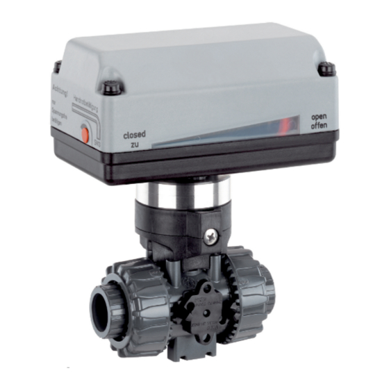
- Page 1 GEMÜ 723 Motorized ball valve Operating instructions further information webcode: GW-723...
- Page 2 All rights including copyrights or industrial property rights are expressly reserved. Keep the document for future reference. © GEMÜ Gebr. Müller Apparatebau GmbH & Co. KG 15.09.2020 GEMÜ 723 2 / 64 www.gemu-group.com...
-
Page 3: Table Of Contents
(Pressure Equipment Directive) ......... 59 20 Declaration of conformity according to 2014/30/EU (EMC Directive) ............60 21 EU Declaration of conformity 2-way ball valve ... 61 22 EU Declaration of conformity 3-way ball valve ... 62 www.gemu-group.com 3 / 64 GEMÜ 723... -
Page 4: General Information
Response(s) to tasks – Lists 1.3 Definition of terms Hot plant components! Working medium The medium that flows through the GEMÜ product. Risk of electric shock 1.4 Warning notes Wherever possible, warning notes are organised according to the following scheme: SIGNAL WORD... -
Page 5: Product Description
FPM, EPDM Ball valve seat seals PTFE 3.2 Description The 2/2 and/or 3/2-way GEMÜ 723 ball valve is motorized. It has a plastic actuator housing. A manual override and an op- tical position indicator are integrated as standard. The seat seal is made from PTFE and the O-ring seals can be made from either EPDM or FKM. -
Page 6: Correct Use
Code L croswitches. The emergency power supply for 24 V DC types is provided by means of an emergency power supply module GEMÜ 1570 (not with actuator version 2070). The opening and closing be- Optional port positions, can be user adjusted haviour is independent of the operating pressure. -
Page 7: Order Data
DN 100 9 Actuator version Code 3 Body configuration Code GEMÜ actuator, motorized, size 1, operating time 4 1006 s, torque 6 Nm, 2/2-way body supply voltage B1, C1, B4, C4 Multi-port version GEMÜ actuator, motorized, size 2, operating time 4... - Page 8 8 Control module On/Off actuator 9 Actuator version 1006 GEMÜ actuator, motorized, size 1, operating time 4 s, torque 6 Nm, supply voltage B1, C1, B4, C4 10 Ball configur./port position T-port, standard end position "Open", connection 1, 2 and 3 open, T-port, standard end position "Closed", connection 1 and 3 open...
-
Page 9: Technical Data
46.2 15.36 12.3 14.7 45.6 15.9 66.0 28.68 23.4 16.2 27.6 63.0 28.5 105.0 35.52 28.5 19.8 36.0 102.0 37.2 204.0 64.08 54.0 37.2 72.0 192.0 73.2 315.0 426.0 570.0 Kv values in m³/h www.gemu-group.com 9 / 64 GEMÜ 723... - Page 10 7200 5080 7200 11141 11141 7725 11141 Weight in g 1) Ball valve material Code 1: PVC-U, grey Code 2: PVC-C, chlorinated polyvinyl chloride Code 4: ABS Code 5: PP-H, grey Code 20: PVDF GEMÜ 723 10 / 64 www.gemu-group.com...
- Page 11 1, 2 11.5 14.8 12.4 14.8 14.8 23.3 Torques in Nm 1) Ball valve material Code 1: PVC-U, grey Code 2: PVC-C, chlorinated polyvinyl chloride Code 4: ABS Code 5: PP-H, grey Code 20: PVDF www.gemu-group.com 11 / 64 GEMÜ 723...
- Page 12 (Code O4) 1006 A0, AE 1015 A0, AE 2006 A0, AE 0.25 2015 A0, AE 3035 A0, AE 2070 00, 0E, 0P 4100 00, 0E, 0P 4200 00, 0E, 0P Current data in A GEMÜ 723 12 / 64 www.gemu-group.com...
- Page 13 Siemens 3RV Siemens 3RV Siemens 3RV switch type 1011-1CA10 1011-1BA10 1011-OGA10 1011-OGA10 Set current 2.20 1.70 0.60 0.45 Current data in A GEMÜ 9468 Motor protection switch Siemens 3RV 1011-1FA10 type: Set current: 4.0 A www.gemu-group.com 13 / 64 GEMÜ 723...
- Page 14 Actuator version 2070: Weights in kg Operating time: Actuator version 1006: Actuator version 1015: Actuator version 2006: Actuator version 2015 (12/24 V): Actuator version 2015 (100–250 V): Actuator version 3035: Operating times in s GEMÜ 723 14 / 64 www.gemu-group.com...
-
Page 15: Dimensions
* Standard with supply voltage code O4 Actuator ver- sion 1006, 1015 2006, 2015 Dimensions in mm 7.1.2 Actuator version 3035, 3055 Voltages 24 V 100.5 100 V - 250 V 124.5 Dimensions in mm www.gemu-group.com 15 / 64 GEMÜ 723... - Page 16 7 Dimensions 7.1.3 Actuator version 2070 121,5 83,5 Dimensions in mm GEMÜ 723 16 / 64 www.gemu-group.com...
- Page 17 Code 4: Flange EN 1092, PN 10, form B, face-to-face dimension FTF EN 558 series 1, ISO 5752, basic series 1 Code 39: Flange ANSI Class 125/150 RF Code 78: Union end with DIN insert (for IR butt welding) www.gemu-group.com 17 / 64 GEMÜ 723...
- Page 18 Code 33: Union end with inch insert - BS (socket) Code 3M: Union end with inch insert - ASTM (socket) Code 3T: Union end with JIS insert (socket) Code 7R: Union end with Rp threaded socket insert GEMÜ 723 18 / 64 www.gemu-group.com...
- Page 19 Code 4: Flange EN 1092, PN 10, form B, face-to-face dimension FTF EN 558 series 1, ISO 5752, basic series 1 Code 39: Flange ANSI Class 125/150 RF Code 3M: Union end with inch insert - ASTM (socket) www.gemu-group.com 19 / 64 GEMÜ 723...
- Page 20 4“ Dimensions in mm 1) Connection type Code 2: Solvent cement or weld socket DIN Code 33: Union end with inch insert - BS (socket) Code 7R: Union end with Rp threaded socket insert GEMÜ 723 20 / 64 www.gemu-group.com...
- Page 21 Code 4: Flange EN 1092, PN 10, form B, face-to-face dimension FTF EN 558 series 1, ISO 5752, basic series 1 Code 39: Flange ANSI Class 125/150 RF Code 78: Union end with DIN insert (for IR butt welding) Code 7R: Union end with Rp threaded socket insert www.gemu-group.com 21 / 64 GEMÜ 723...
- Page 22 Code 4: Flange EN 1092, PN 10, form B, face-to-face dimension FTF EN 558 series 1, ISO 5752, basic series 1 Code 39: Flange ANSI Class 125/150 RF Code 78: Union end with DIN insert (for IR butt welding) GEMÜ 723 22 / 64 www.gemu-group.com...
- Page 23 Code 3M: Union end with inch insert - ASTM (socket) Code 3T: Union end with JIS insert (socket) Code 78: Union end with DIN insert (for IR butt welding) Code 7R: Union end with Rp threaded socket insert www.gemu-group.com 23 / 64 GEMÜ 723...
- Page 24 136.5 188.5 1 ½“ 157.6 227.6 2“ 190.5 190.6 266.5 Dimensions in mm 1) Connection type Code 2: Solvent cement or weld socket DIN Code 3M: Union end with inch insert - ASTM (socket) GEMÜ 723 24 / 64 www.gemu-group.com...
- Page 25 Dimensions in mm 1) Connection type Code 2: Solvent cement or weld socket DIN Code 78: Union end with DIN insert (for IR butt welding) Code 7R: Union end with Rp threaded socket insert www.gemu-group.com 25 / 64 GEMÜ 723...
-
Page 26: Manufacturer's Information
Provide precautionary measures against exceeding the ● 4. Do not store solvents, chemicals, acids, fuels or similar maximum permitted pressures caused by pressure fluids in the same room as GEMÜ products and their spare surges (water hammer). parts. CAUTION Use as step. -
Page 27: Installation With Inserts For Solvent Cementing
7. Push the piping 5 into the insert 4. 8. Screw the union nut 1 to the ball valve body 2 again. 9. Connect the other connections of the ball valve body 2 with the piping 5 in the same manner. www.gemu-group.com 27 / 64 GEMÜ 723... -
Page 28: Installation With Inserts For Welding
7. Screw the insert 4 into the piping 5. 8. Screw the union nut 1 to the ball valve body 2 again. 9. Connect the other connections of the ball valve body 2 with the piping 5 in the same manner. GEMÜ 723 28 / 64 www.gemu-group.com... -
Page 29: Installation With Flanged Connection
7. Connect the valve flange and the piping flange using ap- propriate sealing materials and matching bolting. 8. Use all flange holes. 9. Tighten the bolts diagonally. 10. Re-attach or reactivate all safety and protective devices. www.gemu-group.com 29 / 64 GEMÜ 723... -
Page 30: Electrical Connection
Uv+, direction of travel OPEN Uv-, direction of travel OPEN PE, protective earth conductor Connection diagram Limit switch OPEN External wiring Motor + − PE Limit switch CLOSED Actuator CLOSED Direction of travel CLOSED GEMÜ 723 30 / 64 www.gemu-group.com... - Page 31 10 Electrical connection Actuator OPEN Direction of travel OPEN www.gemu-group.com 31 / 64 GEMÜ 723...
- Page 32 N, supply voltage L1, change-over (OPEN/CLOSE) N, change-over (OPEN/CLOSE) PE, protective earth conductor Preferred direction -OPEN- when all signals are present Connection diagram Limit switch OPEN External wiring Motor Limit switch CLOSED Actuator Laufrichtung CLOSED OPEN GEMÜ 723 32 / 64 www.gemu-group.com...
- Page 33 L1, direction of travel CLOSED N, direction of travel CLOSED L1, direction of travel OPEN N, direction of travel OPEN PE, protective earth conductor The potential must be assigned by the user. Connection diagram External wiring OPEN CLOSED www.gemu-group.com 33 / 64 GEMÜ 723...
- Page 34 Uv+, direction of travel OPEN Uv-, direction of travel OPEN n. c. n. c. PE, protective earth conductor Connection diagram External wiring CLOSED-0-OPEN Actuator CLOSED Direction of travel CLOSED OPEN Direction of travel OPEN GEMÜ 723 34 / 64 www.gemu-group.com...
- Page 35 N, supply voltage L1, change-over (OPEN/CLOSE) N, change-over (OPEN/CLOSE) n. c. n. c. PE, protective earth conductor Preferred direction -OPEN- when all signals are present Connection diagram External wiring L1 N Actuator Laufrichtung CLOSED OPEN www.gemu-group.com 35 / 64 GEMÜ 723...
- Page 36 Uv-, direction of travel CLOSED Uv+, direction of travel OPEN Uv-, direction of travel OPEN PE, protective earth conductor Connection diagram (Actuator) Motor Actuator Motor Actuator (Actuator) Actuator CLOSED Direction of travel CLOSED OPEN Direction of travel OPEN GEMÜ 723 36 / 64 www.gemu-group.com...
- Page 37 Break contact limit switch CLOSED Uv-, direction of travel OPEN Break contact limit switch OPEN n. c. Make contact limit switch OPEN n. c. Change-over contact limit switch OPEN PE, protective earth conductor PE, protective earth conductor www.gemu-group.com 37 / 64 GEMÜ 723...
- Page 38 10 Electrical connection Connection diagram CLOSED OPEN Additional limit switches External wiring CLOSED-0-OPEN Connection assignment X1, UV Connection assignment X2, S1/S2 Actuator CLOSED Direction of travel CLOSED OPEN Direction of travel OPEN GEMÜ 723 38 / 64 www.gemu-group.com...
- Page 39 PE, protective earth conductor Preferred direction -OPEN- when all signals are present Connection diagram OPEN CLOSED Additional limit switches External wiring L1 N Connection diagram X1, UV Connection diagram X2, S1/S2 Actuator Direction of travel CLOSED OPEN www.gemu-group.com 39 / 64 GEMÜ 723...
- Page 40 PE, protective earth conductor PE, protective earth conductor The potential must be assigned by the user. Connection diagram OPEN CLOSED External wiring Additional limit switches OPEN CLOSED Connection diagram X1, UV Connection diagram X2, S1/S2 GEMÜ 723 40 / 64 www.gemu-group.com...
- Page 41 PE, protective earth conductor PE, protective earth conductor Connection diagram CLOSED OPEN Additional limit switches External wiring CLOSED-0 - OPEN Connection diagram X1 Connection diagram X2 Actuator CLOSED Direction of travel CLOSED OPEN Direction of travel OPEN www.gemu-group.com 41 / 64 GEMÜ 723...
- Page 42 PE, protective earth conductor PE, protective earth conductor Preferred direction -OPEN- when all signals are present Connection diagram CLOSED OPEN Additional limit switches External wiring Connection diagram X1 Connection diagram X2 Actuator Direction of travel CLOSED OPEN GEMÜ 723 42 / 64 www.gemu-group.com...
- Page 43 PE, protective earth conductor PE, protective earth conductor The potential must be assigned by the user. Connection diagram CLOSED OPEN External wiring Additional limit switches CLOSED OPEN Connection diagram X1 Connection diagram X2 www.gemu-group.com 43 / 64 GEMÜ 723...
- Page 44 N/Uv- Connection assignment X1 10.3.2 On/Off actuator with 2 additional potential-free limit switches, with relay (code 0E), 24 V DC (code C1) 10.3.2.1 Position of the connectors Actuator version 2070 Actuator version 4100, 4200 GEMÜ 723 44 / 64 www.gemu-group.com...
- Page 45 N/Uv- Connection assignment X1 Connection assignment X2 10.3.3 On/Off actuator with potentiometer output, with relay (code 0P), 24 V DC (code C1) 10.3.3.1 Position of the connectors Actuator version 2070 Actuator version 4100, 4200 www.gemu-group.com 45 / 64 GEMÜ 723...
- Page 46 ▶ The potentiometer will be destroyed if both the limit switch and the potentiometer are connected to the respective termin- als. For this reason, connect either the switch or the potentiometer. Never connect both. ● GEMÜ 723 46 / 64 www.gemu-group.com...
-
Page 47: Commissioning
● tor switch is actuated first. Actuator version 2070 ð Limit switches for signal and motor are already preset. The GEMÜ 9428 motorized actuator is delivered in open posi- tion. The following drawings differ depending on the actuator ver- sion! 1. - Page 48 6. Move limit switches to the desired position. override. 7. Tighten limit switch screws. ▶ Damage to the actuator. Set the actuator position to "centred" before electrical op- ● eration. GEMÜ 723 48 / 64 www.gemu-group.com...
- Page 49 Actu- FREE LOCK ation of the manual override additionally actuates a switch that shuts off power to the actuator. 5. Turn the union nuts 2 to the desired position. www.gemu-group.com 49 / 64 GEMÜ 723...
- Page 50 9. Release the latch 1 of the threaded connection locking device. ð The tooth of the threaded connection locking device engages with the teeth of the union nut 2 and fixes it in place. GEMÜ 723 50 / 64 www.gemu-group.com...
-
Page 51: Troubleshooting
Sealing material faulty Replace sealing material Ball valve body leaking Ball valve body faulty Check ball valve body for potential damage and replace if necessary No flow Ball incorrectly adjusted Turn ball to the correct position www.gemu-group.com 51 / 64 GEMÜ 723... -
Page 52: Inspection And Servicing
3. Shut off plant or plant component. 4. Secure plant or plant component against recommission- ing. 5. Depressurize the plant or plant component. 6. Actuate GEMÜ products which are always in the same po- sition four times a year. GEMÜ 723 52 / 64... - Page 53 Spindle DNXX 717 XXPSP M Ball, T-port DNXX 717 XXPKUMT Ball, L-port DNXX 717 XXPKUML Insert DNXX 717 XXPEL Union nut DNXX 717 XXPUM XX - corresponds to nominal sizes DN 10 – 50. www.gemu-group.com 53 / 64 GEMÜ 723...
- Page 54 Spindle DNXX 717 XXPSP M Ball, T-port DNXX 717 XXPKUMT Ball, L-port DNXX 717 XXPKUML Insert DNXX 717 XXPEL Union nut DNXX 717 XXPUM XX - corresponds to nominal sizes DN 65 – 100. GEMÜ 723 54 / 64 www.gemu-group.com...
- Page 55 Spindle DNXX 717 XXPSP M Ball, T-port DNXX 717 XXPKUMT Ball, L-port DNXX 717 XXPKUML Insert DNXX 717 XXPEL Union nut DNXX 717 XXPUM XX - corresponds to nominal sizes DN 10 – 50. www.gemu-group.com 55 / 64 GEMÜ 723...
- Page 56 13. Carefully press out the ball 6 (taking care not to scratch the ball). 14. Press the spindle(s) 4 (21) into the ball valve body and re- move. 15. Refit all parts in the reverse order. GEMÜ 723 56 / 64 www.gemu-group.com...
-
Page 57: Cleaning The Product
Returned goods can be processed only when this note is completed. If no return delivery note is included with the product, GEMÜ cannot process credits or repair work but will dispose of the goods at the operator's expense. -
Page 58: Declaration Of Incorporation According To 2006/42/Ec (Machinery Directive)
18 Declaration of Incorporation according to 2006/42/EC (Machinery Directive) Declaration of Incorporation according to the EC Machinery Directive 2006/42/EC, Annex II, 1.B for partly completed machinery GEMÜ Gebr. Müller Apparatebau GmbH & Co. KG Fritz-Müller-Straße 6-8 74653 Ingelfingen-Criesbach, Germany declare that the following product Make: GEMÜ... -
Page 59: Declaration Of Conformity According To 2014/68/Eu (Pressure Equipment Directive)
EN 1983, AD 2000 Note for products with a nominal size ≤ DN 25: The products are developed and produced according to GEMÜ process instructions and quality standards which comply with the requirements of ISO 9001 and ISO 14001. According to Article 4, Paragraph 3 of the Pressure Equipment Directive 2014/68/EU these products must not be identified by a CE-label. -
Page 60: Declaration Of Conformity According To 2014/30/Eu (Emc Directive)
20 Declaration of conformity according to 2014/30/EU (EMC Directive) EU Declaration of Conformity in accordance with 2014/30/EU (EMC Directive) GEMÜ Gebr. Müller Apparatebau GmbH & Co. KG Fritz-Müller-Straße 6-8 74653 Ingelfingen-Criesbach, Germany declare that the product listed below complies with the safety requirements of the EMC Directive 2014/30/EU. -
Page 61: Eu Declaration Of Conformity 2-Way Ball Valve
21 EU Declaration of conformity 2-way ball valve 21 EU Declaration of conformity 2-way ball valve The underlined type (VKD) corresponds to GEMÜ 723 (2-way ball valve) www.gemu-group.com 61 / 64 GEMÜ 723... -
Page 62: Eu Declaration Of Conformity 3-Way Ball Valve
22 EU Declaration of conformity 3-way ball valve 22 EU Declaration of conformity 3-way ball valve The underlined type (TKD) corresponds to GEMÜ 723 (3-way ball valve) GEMÜ 723 62 / 64 www.gemu-group.com... - Page 63 GEMÜ 723 63 / 64 www.gemu-group.com...
- Page 64 Subject to alteration GEMÜ Gebr. Müller Apparatebau GmbH & Co. KG Fritz-Müller-Straße 6-8, 74653 Ingelfingen-Criesbach, Germany 09.2020 | 88594472 Phone +49 (0)7940 123-0 · info@gemue.de *88594472* www.gemu-group.com...
Need help?
Do you have a question about the 723 and is the answer not in the manual?
Questions and answers