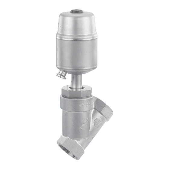
GEM 550 Installation, Operating And Maintenance Instructions
Angle seat globe valve
Hide thumbs
Also See for 550:
- Assembly instructions manual (16 pages) ,
- Operating instructions manual (46 pages) ,
- Installation, operating, & maintenance instructions (44 pages)
Table of Contents
Advertisement
Available languages
Available languages
Quick Links
Advertisement
Chapters
Table of Contents

Subscribe to Our Youtube Channel
Related Manuals for GEM 550


Summary of Contents for GEM 550
- Page 1 Schrägsitzventil Metall, DN 8 - 80 Angle Seat Globe Valve Metal, DN 8 - 80 ORIGINAL EINBAU- UND MONTAGEANLEITUNG INSTALLATION, OPERATING AND MAINTENANCE INSTRUCTIONS Antrieb 0 und 1 Antrieb 2 bis 5 Actuator 0 and 1 Actuator 2 to 5 550_us...
-
Page 2: Table Of Contents
Inhaltsverzeichnis Allgemeine Hinweise Allgemeine Hinweise Voraussetzungen für die einwandfreie Funk- Allgemeine Sicherheitshinweise 2 tion des GEMÜ-Ventils: Hinweise für Service- und Sachgerechter Transport und Lagerung. Bedienpersonal Installation und Inbetriebnahme durch Warnhinweise eingewiesenes Fachpersonal. Verwendete Symbole Bedienung gemäß dieser Einbau- und Begriff sbestimmungen Montageanleitung. -
Page 3: Hinweise Für Service- Und
Hinweise für Service- Warnhinweise und Bedienpersonal Warnhinweise sind, soweit möglich, nach folgendem Schema gegliedert: Die Einbau- und Montageanleitung enthält grundlegende Sicherheitshinweise, die bei SIGNALWORT Inbetriebnahme, Betrieb und Instandhaltung zu beachten sind. Nichtbeachtung kann zur Art und Quelle der Gefahr Folge haben: ®... -
Page 4: Verwendete Symbole
Verwendete Symbole Vorgesehener Einsatzbereich Das 2/2-Wege-Ventil GEMÜ 550 ist für Gefahr durch heiße Oberfl ächen! den Einsatz in Rohrleitungen konzipiert. Es steuert ein durchfl ießendes Medium indem es durch ein Steuermedium Gefahr durch ätzende Stoff e! geschlossen oder geöff net werden kann. -
Page 5: Technische Daten
Technische Daten Durchfl ussmedium Umgebungsbedingungen Aggressive, neutrale, gasförmige und flüssige Medien, die Umgebungstemperatur max. 60° C die physikalischen und chemischen Eigenschaften des jeweiligen Gehäuse- und Dichtwerkstoffes nicht negativ Steuermedium beeinflussen. Max. zul. Druck des Betriebsmediums s. Tabelle Neutrale Gase Medientemperatur -10°... - Page 6 Betriebsdruck- / Steuerdruckkennlinien Durchflussrichtung: mit dem Teller / Steuerfunktion: Federkraft geschlossen (NC) Antriebsgröße 0 Antriebsgröße 1 min. Steuerdruck in Abhängigkeit vom Betriebsdruck min. Steuerdruck in Abhängigkeit vom Betriebsdruck DN20 DN8/10/15 DN15 DN10/12 Betriebsdruck [bar] Betriebsdruck [bar] Betriebsdruck [bar] Betriebsdruck [bar] Antriebsgröße 2 Antriebsgröße 3 min.
- Page 7 Betriebsdruck- / Steuerdruckkennlinien Durchflussrichtung: gegen den Teller / Steuerfunktion: Federkraft geöffnet (NO) Antriebsgröße 0 Antriebsgröße 1 min. Steuerdruck in Abhängigkeit vom Betriebsdruck min. Steuerdruck in Abhängigkeit vom Betriebsdruck DN20 DN8/10/15 DN15 DN10/12 Betriebsdruck [bar] Betriebsdruck [bar] Betriebsdruck [bar] Betriebsdruck [bar] Antriebsgröße 2 Antriebsgröße 3 min.
- Page 8 Betriebsdruck- / Steuerdruckkennlinien Durchflussrichtung: gegen den Teller / Steuerfunktion: Beidseitig angesteuert (DA) Antriebsgröße 0 Antriebsgröße 1 min. Steuerdruck in Abhängigkeit vom Betriebsdruck min. Steuerdruck in Abhängigkeit vom Betriebsdruck DN20 DN8/10/15 DN15 DN10/12 Betriebsdruck [bar] Betriebsdruck [bar] Betriebsdruck [bar] Betriebsdruck [bar] Antriebsgröße 2 Antriebsgröße 3 min.
-
Page 9: Bestelldaten
Bestelldaten Steuerfunktion Code Gehäuseform Code Federkraft geschlossen (NC) Durchgangskörper Federkraft geöffnet (NO) Anschlussart Code Beidseitig angesteuert (DA) Schweißstutzen Beidseitig angesteuert (in Ruhestellung geöffnet) Stutzen DIN (nur für Regelventile) Stutzen DIN 11850, Reihe 1 Stutzen DIN 11850, Reihe 2 Antriebsgröße Code Stutzen DIN 11850, Reihe 3 Antrieb 0 Kolben ø... -
Page 10: Herstellerangaben
Herstellerangaben Funktionsbeschreibung Das fremdgesteuerte 2/2 Wege-Ventil GEMÜ Transport 550 ist ein Metall-Schrägsitzventil mit Durch- gangskörper und besitzt einen Kolbenantrieb. Ventil nur auf geeignetem Lademittel Die Ventilkörper sind gemäß Datenblatt in transportieren, nicht stürzen, vorsichtig verschiedenen Ausführungen erhältlich. handhaben. Das Ventil hat bei Steuerfunktion NC serien- Verpackungsmaterial entsprechend mäßig eine optische Stellungsanzeige (für... -
Page 11: Geräteaufbau
10 Geräteaufbau 11 Montage und Anschluss Vor Einbau: Ventilkörperwerkstoff und Sitzdichtung entsprechend Betriebsmedium auslegen. Eignung vor Einbau prüfen! Siehe Kapitel 6 "Technische Daten". 11.1 Montage des Ventils WARNUNG Unter Druck stehende Armaturen! ® Gefahr von schwersten Verletzungen oder Tod! Nur an druckloser Anlage arbeiten. WARNUNG Geräteaufbau Haube steht unter Federdruck! - Page 12 Montagearbeiten nur durch geschultes Die Durchfl ussrichtung ist durch einen Fachpersonal. Pfeil auf dem Ventilkörper gekennzeichnet: Geeignete Schutzausrüstung gemäß den Regelungen des Anlagenbetreibers berücksichtigen. Installationsort: VORSICHT gegen den Teller mit dem Teller Ventil äußerlich nicht stark beanspruchen. Montage: Installationsort so wählen, dass Ventil 1.
-
Page 13: Bedienung
11.3 Steuerfunktionen Montage bei Gewindeanschluss: Gewindeanschluss entsprechend der Folgende Steuerfunktionen sind verfügbar: gültigen Normen in Rohr einschrauben. Ventilkörper an Rohrleitung anschrauben, Steuerfunktion 1 geeignetes Gewindedichtmittel Federkraft geschlossen (NC): verwenden. Das Gewindedichtmittel ist nicht im Lieferumfang enthalten. Ruhezustand des Ventils: durch Federkraft geschlossen. -
Page 14: Steuermedium Anschließen
11.4 Steuermedium anschließen Wichtig: Steuermediumleitungen span- Anschluss 2 nungs- und knickfrei montieren! Je nach Anwendung geeignete Anschlussstücke verwenden. Steuerfunktion 1 Gewinde der Steuermediumanschlüsse 2 und 4: Antriebsgröße Gewinde Anschluss 4 1, 2 G 1/8 Anschluss 2 3, 4, 5 G 1/4 Steuerfunktion Anschluss Federkraft ge-... -
Page 15: Montage / Demontage Von Ersatzteilen
12 Montage / Demontage 12.3 Montage Antrieb von Ersatzteilen und Dichtring 4 Siehe auch Kapitel 11.1 "Montage des Ven- 1. Antrieb A in Off en-Position bringen. tils" und Kapitel 20 "Schnittbild und Ersatz- 2. Neuen Dichtring 4 in Ventilkörper 1 teile". -
Page 16: Inbetriebnahme
13 Inbetriebnahme 14 Inspektion und Wartung WARNUNG WARNUNG Aggressive Chemikalien! Unter Druck stehende Armaturen! ® Verätzungen! ® Gefahr von schwersten Verletzungen Vor Inbetriebnahme Dichtheit oder Tod! der Medienanschlüsse Nur an druckloser Anlage arbeiten. prüfen! Dichtheitsprüfung nur mit ge- VORSICHT eigneter Schutzausrüstung. Heiße Anlagenteile! ®... -
Page 17: Demontage
15 Demontage 18 Hinweise Demontage erfolgt unter den gleichen Hinweis zur Richtlinie 94/9/EG Vorsichtsmaßnahmen wie die Montage. (ATEX Richtlinie): Ventil demontieren (siehe Kapitel 12.1 Ein Beiblatt zur Richtlinie 94/9/EG "Demontage Antrieb und Dichtring 4"). liegt dem Produkt bei, sofern es Leitung des Steuermediums abschrauben gemäß... -
Page 18: Fehlersuche / Störungsbehebung
19 Fehlersuche / Störungsbehebung Fehler Möglicher Grund Fehlerbehebung Steuermedium entweicht aus Entlüftungsbohrung* im Antrieb austauschen und Steuermedium auf Antriebsdeckel bei Steuer- Steuerkolben undicht Verschmutzungen untersuchen funktion 1 (NC) / Anschluss 2* bei Steuerfunktion 2 (NO) Steuermedium entweicht Antrieb austauschen und Steuermedium auf Spindelabdichtung undicht aus Leckagebohrung* Verschmutzungen untersuchen... -
Page 19: Schnittbild Und Ersatzteile
20 Schnittbild und Ersatzteile Entlüftungsbohrung Anschluss 4 Anschluss 2 Leckagebohrung Pos. Benennung Bestellbezeichnung Ventilkörper K 500... Dichtring 550...SVS... Sitzdichtung Antrieb 9550 Überwurfmutter Spindel Ventilteller Mutter Scheibe 550_us 19 / 44... -
Page 20: Einbauerklärung
29.12.2009 Projektnummer: SV-Pneum-2009-12 Handelsbezeichnung: Typ 550 Es wird erklärt, dass die folgenden grundlegenden Anforderungen der Maschinenrichtlinie 2006/42/EG erfüllt sind: 1.1.3.; 1.1.5.; 1.1.7.; 1.2.1.; 1.3.; 1.3.2.; 1.3.3.; 1.3.4.; 1.3.7.; 1.3.9.; 1.5.3.; 1.5.5.; 1.5.6.; 1.5.7.; 1.5.8.; 1.5.9.; 1.6.5.; 2.1.1.; 3.2.1.; 3.2.2.; 3.3.2.; 3.4.4.; 3.6.3.1.; 4.1.2.1.; 4.1.2.3.; 4.1.2.4.; 4.1.2.5.; 4.1.2.6. a); 4.1.2.6. b);... -
Page 21: Eg-Konformitätserklärung
GEMÜ Gebr. Müller GmbH & Co. KG Fritz-Müller-Straße 6-8 D-74653 Ingelfi ngen erklären, dass unten aufgeführte Armaturen die Sicherheitsanforderungen der Druckgeräte- richtlinie 97/23/EG erfüllen. Benennung der Armaturen - Typenbezeichnung Sitzventil GEMÜ 550 Benannte Stelle: TÜV Rheinland Berlin Brandenburg Nummer: 0035 Zertifi kat-Nr.: 01 202 926/Q-02 0036 Konformitätsbewertungsverfahren:... - Page 22 Contents General notes General notes Prerequisites for the correct functioning of General safety notes the GEMÜ valve: Notes for servicing and Proper transport and storage. operating personnel Installation and commissioning by trained Warning notes specialist staff . Symbols used Operation according to these installation, Defi...
-
Page 23: Notes For Servicing And Operating Personnel
Notes for servicing and Warning notes operating personnel Wherever possible, warning notes are organised according following The installation, operating and maintenance instructions contain fundamental safety scheme: notes that must be observed during commis- sioning, operation, and maintenance. Non- SIGNAL WORD observance can cause: Type and source of the danger ®... -
Page 24: Symbols Used
Symbols used Limited use Danger - hot surfaces! The GEMÜ 2/2-way valve is designed for installation in piping systems. It controls a fl owing medium by being closed or Danger - corrosive materials! opened by a control medium. The valve may only be used providing the product technical criteria are Hand: indicates general notes and complied with (see chapter 6... -
Page 25: Technical Data
Technical data Working medium Ambient conditions Max. ambient temperature 60° C Corrosive, inert, gaseous and liquid media which have no negative impact on the physical and chemical properties of the body and seal material. Control medium Max. perm. pressure of working medium see table Inert gases Media temperature... - Page 26 Operating pressure / Control pressure characteristics Flow direction: over the seat / Control function: Normally closed (NC): Actuator size 0 Actuator size 1 Min. control pressure dependent on operating pressure Min. control pressure dependent on operating pressure DN20 DN8/10/15 DN15 DN10/12 Operating pressure [bar] Operating pressure [bar]...
- Page 27 Operating pressure / Control pressure characteristics Flow direction: under the seat / Control function: Normally open (NO): Actuator size 0 Actuator size 1 Min. control pressure dependent on operating pressure Min. control pressure dependent on operating pressure DN20 DN8/10/15 DN15 DN10/12 Operating pressure [bar] Betriebsdruck [bar]...
- Page 28 Operating pressure / Control pressure characteristics Flow direction: under the seat / Control function: Double acting (DA): Actuator size 0 Actuator size 1 Min. control pressure dependent on operating pressure Min. control pressure dependent on operating pressure DN20 DN8/10/15 DN15 DN10/12 Operating pressure [bar] Operating pressure [bar]...
-
Page 29: Order Data
Order data Control function Code Body confi guration Code Normally closed (NC) 2/2-way body Normally open (NO) Connection Code Double acting (DA) Butt weld spigots Double acting (normally open) Spigots DIN (only for control valves) Spigots DIN 11850, series 1 Spigots DIN 11850, series 2 Actuator size Code... -
Page 30: Manufacturer's Information
Manufacturer’s information Function description The GEMÜ 550 pneumatically operated 2/2- Transport way valve is a metal angle seat globe valve with a straight through body and a piston actuator. The valve bodies are available in Only transport the valve with various designs as shown in the data sheet. -
Page 31: Construction
10 Construction WARNING The actuator cover is under spring pressure! ® Risk of severe injury or death! Do not open the actuator! WARNING Corrosive chemicals! ® Risk of caustic burns! Wear appropriate protective gear when assembling. WARNING Hot plant components! Construction ®... - Page 32 Installation location: concentration, temperature and pressure) and the prevailing ambient CAUTION conditions. Check the technical data of the valve and the materials. Do not apply external force to the valve. Choose the installation location so that Shut off pressure line or process the valve cannot be used as a foothold.
-
Page 33: Operation
11.3 Control functions Assembly - Flange connection: Install the valve in the condition it is delivered The following control functions are available: 1. Pay attention to clean, undamaged Control function 1 sealing surfaces on the mating fl anges. Normally closed (NC): 2. -
Page 34: Connecting The Control Medium
11.4 Connecting the control medium Important: Connector 2 Assemble the control medium lines tension-free and without any bends or knots! Use appropriate connectors Control function 1 according to the application. Thread size for the control medium connectors 2 and 4: Connector 4 Actuator size Thread... -
Page 35: Assembly / Disassembly Of Spare Parts
12 Assembly / disassembly 12.3 Assembly of actuator of spare parts and gasket 4 See also chapter 11.1 "Assembling the 1. Move actuator A to the open position. valve" and chapter 20 "Sectional drawing and 2. Insert new gasket 4 in valve body 1. spare parts". -
Page 36: Commissioning
13 Commissioning 14 Inspection and servicing WARNING WARNING Corrosive chemicals! The equipment is subject to pressure! ® Risk of caustic burns! ® Risk of severe injury or death! Check the tightness of the Only work on depressurized plant. media connections prior to commissioning! WARNING Use only the appropriate... -
Page 37: Disassembly
17 Returns Important: Service and maintenance: Seals Clean the valve. degrade in the course of time. Returns must be made with a completed After valve assembly / disassembly declaration of return (included). check that the union nut is tight and If not completed, GEMÜ... -
Page 38: Troubleshooting / Fault Clearance
Troubleshooting / Fault clearance Fault Possible cause Fault clearance Control medium escapes from vent hole* in the actuator Replace actuator and check control medium cover (for control function 1 Control piston leaky for impurities (NC)) or connector 2* (for control function 2 (NO)) Control medium escapes Replace actuator and check control medium Spindle seal leaking... -
Page 39: Sectional Drawing And Spare Parts
20 Sectional drawing and spare parts Vent hole Connector 4 Connector 2 Leak detection hole Item Name Order description Valve body K 500... Gasket 550...SVS... Seat seal Actuator 9550 Union nut Spindle Valve plug Washer 550_us 39 / 44... -
Page 40: Declaration Of Incorporation
Project number: SV-Pneum-2009-12 Commercial name: Type 550 We hereby declare that the following essential requirements of the Machinery Directive 2006/42/ EC have been fulfilled: 1.1.3.; 1.1.5.; 1.1.7.; 1.2.1.; 1.3.; 1.3.2.; 1.3.3.; 1.3.4.; 1.3.7.; 1.3.9.; 1.5.3.; 1.5.5.; 1.5.6.; 1.5.7.; 1.5.8.; 1.5.9.;... -
Page 41: Ec Declaration Of Conformity
D-74653 Ingelfi ngen declare that the equipment listed below complies with the safety requirements of the Pressure Equipment Directive 97/23/EC. Description of the equipment - product type Globe valve GEMÜ 550 Notifi ed body: TÜV Rheinland Berlin Brandenburg Number: 0035 Certifi... - Page 42 Rücksendeerklärung (Kopiervorlage) Gesetzliche Bestimmungen, der Schutz der Umwelt und des Personals erfordern es, diese Erklärung vollständig ausgefüllt und unterschrieben den Versandpapieren beizulegen. Wenn diese Erklärung nicht vollständig ausgefüllt ist oder den Versandpapieren nicht beigelegt ist wird Ihre Rücksendung nicht bearbeitet! Wurde das Ventil / Gerät mit giftigen, ätzenden, brennbaren, aggressiven oder wassergefährdenden Medien betrieben, alle mediumsberührten Teile sorgfältig entleeren, dekontaminieren und spülen.
- Page 43 Goods return declaration (copy specimen) Legal regulations for the protection of the environment and personnel require that you include the completed and signed goods return declaration with your dispatch documents. If this declaration is not completed or not included with the dispatch documents, your return will not be processed! If the valve / device was operated with poisonous, corrosive, flammable, aggressive or water- endangering media, all medium wetted parts must be emptied carefully, decontaminated and rinsed.
- Page 44 VENTIL-, MESS- UND REGELSYSTEME VALVES, MEASUREMENT AND CONTROL SYSTEMS GEMÜ Gebr. Müller Apparatebau GmbH & Co. KG · Fritz-Müller-Str. 6-8 · D-74653 Ingelfi ngen-Criesbach Telefon +49(0)7940/123-0 · Telefax +49(0)7940/123-192 · info@gemue.de · www.gemue.de...
Need help?
Do you have a question about the 550 and is the answer not in the manual?
Questions and answers