GEM 675 Operating Instructions Manual
Manually operated diaphragm valve
Hide thumbs
Also See for 675:

Subscribe to Our Youtube Channel
Related Manuals for GEM 675


Summary of Contents for GEM 675
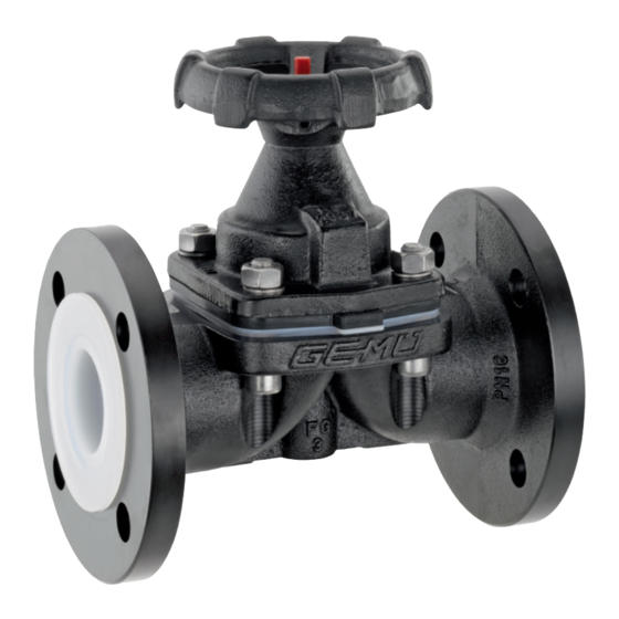
- Page 1 GEMÜ 675 Manually operated diaphragm valve Operating instructions further information webcode: GW-675...
- Page 2 All rights including copyrights or industrial property rights are expressly reserved. Keep the document for future reference. © GEMÜ Gebr. Müller Apparatebau GmbH & Co. KG 17.11.2020 GEMÜ 675 2 / 27 www.gemu-group.com...
-
Page 3: Table Of Contents
Mounting the actuator ........23 13 Troubleshooting ............24 14 Removal from piping ..........25 15 Disposal ..............25 16 Returns ..............25 17 Declaration of conformity according to 2014/68/EU (Pressure Equipment Directive) ......... 26 www.gemu-group.com 3 / 27 GEMÜ 675... -
Page 4: General Information
Working medium The medium that flows through the GEMÜ product. Diaphragm size Handwheel can become hot during operation! Uniform seat size of GEMÜ diaphragm valves for different nominal sizes. 1.4 Warning notes Wherever possible, warning notes are organised according to... -
Page 5: Safety Information
8. Observe the safety regulations for the media used. 3.2 Description During operation: The GEMÜ 675 2/2-way diaphragm valve has a metal hand- 9. Keep this document available at the place of use. wheel and is manually operated. An integral optical position 10. -
Page 6: Correct Use
The product is designed for installation in piping systems and for controlling a working medium. The product is not intended for use in potentially explosive areas. ● Use the product in accordance with the technical data. GEMÜ 675 6 / 27 www.gemu-group.com... -
Page 7: Order Data
Actuator size 6 Flange ANSI Class 125/150 RF, face-to-face dimension FTF EN 558 series 7, ISO DN 150, diaphragm size 150 5752, basic series 7, Actuator size 7 length only for body configuration D www.gemu-group.com 7 / 27 GEMÜ 675... -
Page 8: Order Example
FTF EN 558 series 1, ISO 5752, basic series 1, length only for body configuration D 5 Valve body material EN-GJL-250 (GG 25) 6 Diaphragm material EPDM 7 Control function Manually operated (MO) 8 Actuator version Actuator size 2 GEMÜ 675 8 / 27 www.gemu-group.com... -
Page 9: Technical Data
Sealing at the valve seat and atmospheric sealing is ensured for the given values. Information on operating pressures applied on both sides and for high purity media on request. Pressure rating: PN 16 Leakage rate: Leakage rate A (acc. to EN 12266-1) www.gemu-group.com 9 / 27 GEMÜ 675... -
Page 10: Product Compliance
The product complies with the requirements according to VDI 2440 (November 2000), VDI 3479, DIN EN ISO 158481, certificate no. 18 11 090235 002* * see availability 6.5 Mechanical data Weight: Actuator Actuator version Weight 12.0 15.0 25.0 Weights in kg GEMÜ 675 10 / 27 www.gemu-group.com... - Page 11 6 Technical data Weight: Body Threaded socket Flange Connection types code 8, 38, 39, 51, 53, 56 10.2 14.2 21.0 30.0 35.0 MG = diaphragm size, weight in kg Installation position: Optional Flow direction: Optional www.gemu-group.com 11 / 27 GEMÜ 675...
-
Page 12: Dimensions
7 Dimensions 7 Dimensions 7.1 Actuator dimensions ø B Actuator version ø B 15 - 25 32 - 40 Dimensions in mm, MG = diaphragm size * CT = A + H1 (see body dimensions) GEMÜ 675 12 / 27 www.gemu-group.com... -
Page 13: Body Dimensions
Code 8: Flange EN 1092, PN 16, form B, face-to-face dimension FTF EN 558 series 1, ISO 5752, basic series 1, length only for body configur- ation D 2) Valve body material Code 8: EN-GJL-250 (GG 25) Code 17: EN-GJS-400-18-LT (GGG 40.3), PFA lined Code 18: EN-GJS-400-18-LT (GGG 40.3), PP lined Code 83: EN-GJS-400-18-LT (GGG 40.3), hard rubber lined www.gemu-group.com 13 / 27 GEMÜ 675... -
Page 14: Flange En (Code 53)
Code 53: Flange EN 1092, PN 16, form A, face-to-face dimension FTF EN 558 series 7, ISO 5752, basic series 7, length only for body config- uration D 2) Valve body material Code 8: EN-GJL-250 (GG 25) Code 17: EN-GJS-400-18-LT (GGG 40.3), PFA lined 3) Diameter deviates from standard GEMÜ 675 14 / 27 www.gemu-group.com... -
Page 15: Flange Ansi Class (Code 38, 39)
Code 8: EN-GJL-250 (GG 25) Code 17: EN-GJS-400-18-LT (GGG 40.3), PFA lined Code 18: EN-GJS-400-18-LT (GGG 40.3), PP lined Code 83: EN-GJS-400-18-LT (GGG 40.3), hard rubber lined 3) Connection code 39 / material code 8 ØD = 220 www.gemu-group.com 15 / 27 GEMÜ 675... -
Page 16: Flange Ansi Class (Code 56)
Code 56: Flange ANSI Class 125/150 RF, face-to-face dimension FTF EN 558 series 7, ISO 5752, basic series 7, length only for body config- uration D 2) Valve body material Code 17: EN-GJS-400-18-LT (GGG 40.3), PFA lined Code 81: EN-GJS-500-7 (GGG 50), PFA lined Code 91: EN-GJS-500-7 (GGG 50), PP lined GEMÜ 675 16 / 27 www.gemu-group.com... -
Page 17: Flange Bs (Code 51)
Code 51: Flange BS 10 Table "E", face-to-face dimension FTF EN 558 series 7, ISO 5752, basic series 7, length only for body configuration D 2) Valve body material Code 17: EN-GJS-400-18-LT (GGG 40.3), PFA lined Code 81: EN-GJS-500-7 (GGG 50), PFA lined Code 91: EN-GJS-500-7 (GGG 50), PP lined www.gemu-group.com 17 / 27 GEMÜ 675... -
Page 18: Threaded Socket Din (Code 1)
35.0 18.0 165.0 Dimensions in mm, MG = diaphragm size n = number of flats 1) Connection type Code 1: Threaded socket DIN ISO 228 2) Valve body material Code 8: EN-GJL-250 (GG 25) GEMÜ 675 18 / 27 www.gemu-group.com... -
Page 19: Manufacturer's Information
Use appropriate, functional and safe tools. 4. Do not store solvents, chemicals, acids, fuels or similar ● fluids in the same room as GEMÜ products and their spare 1. Ensure the product is suitable for the relevant application. parts. 2. Check the technical data of the product and the materials. -
Page 20: Installation With Flanged Connections
10. Re-attach or reactivate all safety and protective devices. 9.3 Installation with threaded sockets NOTICE Fig. 2: Threaded socket Lockable handwheel ▶ A lockable handwheel is optionally available. It can be se- cured with a padlock. GEMÜ 675 20 / 27 www.gemu-group.com... -
Page 21: Commissioning
5. Depressurize the plant or plant component. 1. Check the tightness and the function of the product (close 6. Actuate GEMÜ products which are always in the same po- and reopen the product). Due to the setting behavior of sition four times a year. -
Page 22: Mounting The Diaphragm
5. Clean all parts of contamination (do not damage parts dur- ing cleaning). 6. Check parts for potential damage, replace if necessary (only use genuine parts from GEMÜ). 12.3 Removing the diaphragm 1. Remove actuator A (see chapter "Removing the actuator"). -
Page 23: Mounting The Concave Diaphragm
5. Fully tighten the bolts with nuts diagonally. 6. Ensure even compression of the diaphragm (approx. 10 to 15%). ð Even compression is detected by an even outer bulge. 7. With the valve fully assembled, check the function and tightness. www.gemu-group.com 23 / 27 GEMÜ 675... -
Page 24: Troubleshooting
Valve body leaks Valve body leaks or is corroded Check valve body for damage, replace valve body if necessary Handwheel cannot be turned Handwheel defective Replace the handwheel Handwheel clamp locked Unlock handwheel clamp GEMÜ 675 24 / 27 www.gemu-group.com... -
Page 25: Removal From Piping
Returned goods can be processed only when this note is completed. If no return delivery note is included with the product, GEMÜ cannot process credits or repair work but will dispose of the goods at the operator's expense. -
Page 26: Declaration Of Conformity According To 2014/68/Eu (Pressure Equipment Directive)
AD 2000 Note for products with a nominal size ≤ DN 25: The products are developed and produced according to GEMÜ process instructions and quality standards which comply with the requirements of ISO 9001 and ISO 14001. According to Article 4, Paragraph 3 of the Pressure Equipment Directive 2014/68/EU these products must not be identified by a CE-label. - Page 27 Subject to alteration GEMÜ Gebr. Müller Apparatebau GmbH & Co. KG *88710491* Fritz-Müller-Straße 6–8, 74653 Ingelfingen-Criesbach, Germany 11.2020 | 88710491 Phone +49 (0) 7940 1230 · info@gemue.de www.gemu-group.com...
Need help?
Do you have a question about the 675 and is the answer not in the manual?
Questions and answers