
Subscribe to Our Youtube Channel
Related Manuals for GEM 768


Summary of Contents for GEM 768
- Page 1 GEMÜ 768 Motorized compact flanged ball valve Operating instructions further information webcode: GW-768...
- Page 2 All rights including copyrights or industrial property rights are expressly reserved. Keep the document for future reference. © GEMÜ Gebr. Müller Apparatebau GmbH & Co. KG 11.12.2019 GEMÜ 768 2 / 40 www.gemu-group.com...
-
Page 3: Table Of Contents
Warning notes ............. 2 Safety information ............ 3 Product description ........... Construction ............Function ............... 4 GEMÜ CONEXO ............5 Correct use ............... 6 Order data ..............7 Technical data ............8 Dimensions ............... 13 9 Manufacturer's information ........17 Delivery .............. -
Page 4: General Information
Response(s) to tasks – Lists 1.3 Definition of terms Hot plant components! Working medium The medium that flows through the GEMÜ product. Risk of electric shock 1.4 Warning notes Wherever possible, warning notes are organised according to the following scheme: SIGNAL WORD... -
Page 5: Safety Information
13. Maintain the product correctly. 14. Do not carry out any maintenance work and repairs not de- scribed in this document without consulting the manufac- turer first. In cases of uncertainty: 15. Consult the nearest GEMÜ sales office. www.gemu-group.com 5 / 40 GEMÜ 768... -
Page 6: Function
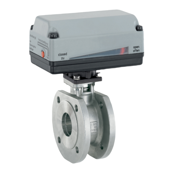
For further information please read the operating instructions for CONEXO products or the CONEXO datasheet. The GEMÜ 768 2/2-way metal ball valve is motorized. It has a Products such as the CONEXO app, the CONEXO portal and plastic actuator housing. A manual override and an optical po- the CONEXO pen are not included in the scope of delivery and sition indicator are integrated as standard. -
Page 7: Order Data
Control actuator, external set value 0/4–20 mA 3 Ball configur./port position Code 9 Actuator version Code 2/2-way body GEMÜ actuator, motorized, size 1, operating time 1015 4 Connection type Code 11 s, torque 15 Nm, supply voltage B1, C1 Flange ANSI class 125/150 RF, up to DN 100 face-to-face dimension FTF EN 558 GEMÜ... - Page 8 6 Seal material PTFE 7 Voltage/Frequency 24 VDC 8 Control module On/Off actuator 9 Actuator version 1015 GEMÜ actuator, motorized, size 1, operating time 11 s, torque 15 Nm, supply voltage B1, C1 10 CONEXO without 8 / 40 GEMÜ 768 www.gemu-group.com...
-
Page 9: Technical Data
PN 40 Kv values: Kv values 1/2” 12.8 3/4” 29.1 1” 47.8 1¼” 1½” 2” 213.7 2½” 273.3 3” 495.3 4” 871.1 Kv values in m³/h 7.4 Product compliance Machinery Directive: 2006/42/EC EMC Directive: 2014/30/EU 9 / 40 www.gemu-group.com GEMÜ 768... - Page 10 3” 12.5 4” Actuator Actuator version 1015: Actuator version 2015 (12/24 Actuator version 2015 (100– 250 V): Actuator version 3035: Actuator version 2070: Actuator version 4100: 11.6 Actuator version 4200: 11.6 Weights in kg 10 / 40 GEMÜ 768 www.gemu-group.com...
- Page 11 1006 A0, AE 1015 A0, AE 2006 A0, AE 2015 A0, AE 3035 A0, AE 2070 00, 0E, 0P 14.0 4100 00, 0E, 0P 35.0 4200 00, 0E, 0P 35.0 Current data in A 11 / 40 www.gemu-group.com GEMÜ 768...
- Page 12 Current data in A Supply voltage 12 V / 24 V: Motor protective system by customer Supply voltage 100 - 250 V: Integrated stall and overload protection plus excess current release T 1A 5x20 mm 12 / 40 GEMÜ 768 www.gemu-group.com...
-
Page 13: Dimensions
* Standard with supply voltage code O4 Actuator ver- sion 1006, 1015 2006, 2015 Dimensions in mm 8.1.2 Actuator version 3035 Voltages 24 V 100.5 100 V - 250 V 124.5 Dimensions in mm 13 / 40 www.gemu-group.com GEMÜ 768... - Page 14 8 Dimensions 8.1.3 Actuator version 2070 121,5 83,5 Dimensions in mm 8.1.4 Actuator version 4100, 4200 277,5 Dimensions in mm 14 / 40 GEMÜ 768 www.gemu-group.com...
- Page 15 8.1.5.2 Connection dimensions actuator version (10XX, 20XX, 3035) DIN ISO 5211 Actuator version Connection size Location spigot (code) (code) (code) 10XX / 20XX Ø5.5 10XX / 20XX 10XX / 20XX 10XX / 20XX 10XX / 20XX 3035 Dimensions in mm 15 / 40 www.gemu-group.com GEMÜ 768...
- Page 16 ø6x4 ø6x4 ø6x4 ø6x4 ø6x4 ø7x4 ø6x4 ø7x4 11.3 100 ø7x4 ø9x4 88.5 15.5 110 ø7x4 ø9x4 ø9x4 ø11x4 109.7 15.8 145 ø9x4 ø11x4 119.5 ø9 x 4 ø11x4 M16 100 132.7 17.8 180 16 / 40 GEMÜ 768 www.gemu-group.com...
-
Page 17: Manufacturer's Information
Provide precautionary measures against exceeding the ● 4. Do not store solvents, chemicals, acids, fuels or similar maximum permitted pressures caused by pressure fluids in the same room as GEMÜ products and their spare surges (water hammer). parts. CAUTION Use as step. -
Page 18: Installation For Flanged Connection
5. Centre the seals D accurately. Seals are not included in the scope of delivery. 6. Connect the ball valve flange and the piping flange using appropriate sealing material and matching bolting. Sealing material and bolts are not included in the scope of deliv- ery. GEMÜ 768 18 / 40 www.gemu-group.com... - Page 19 8. Slightly tighten the bolts SN and nuts M diagonally. 9. Check the alignment of the piping. 10. Tighten nuts M diagonally. Comply with appropriate regulations for the connections! After the installation: 11. Re-attach or reactivate all safety and protective devices. www.gemu-group.com 19 / 40 GEMÜ 768...
-
Page 20: Electrical Connection
Uv-, direction of travel OPEN PE, protective earth conductor Connection diagram Limit switch OPEN External wiring Motor + − PE Limit switch CLOSED Actuator CLOSED Direction of travel CLOSED OPEN Direction of travel OPEN 20 / 40 GEMÜ 768 www.gemu-group.com... - Page 21 L1, direction of travel CLOSED N, direction of travel CLOSED L1, direction of travel OPEN N, direction of travel OPEN PE, protective earth conductor The potential must be assigned by the user. Connection diagram External wiring OPEN CLOSED 21 / 40 www.gemu-group.com GEMÜ 768...
-
Page 22: Connection And Wiring Diagram - Actuator Version 2070, 4100, 4200
When the OPEN and CLOSED switches are operated simultaneously the actuator moves in the "CLOSED" direction. Pins 2, 4 and 6 can be connected in the connector plug, so you can also use a 5-wire cable. Connection diagram L1/ Uv+ External wiring N / Uv- OPEN CLOSED 22 / 40 GEMÜ 768 www.gemu-group.com... - Page 23 Pins 2, 4 and 6 can be connected in the connector plug, so you can also use a 5-wire cable. Connection diagram OPEN CLOSED L1/ Uv+ External wiring N / Uv- Additional limit switches OPEN CLOSED Connection assignment X1 Connection assignment X2 23 / 40 www.gemu-group.com GEMÜ 768...
- Page 24 Pins 2, 4 and 6 can be connected in the connector plug, so you can also use a 5-wire cable. Connection diagram Actual value potentiometer L1/ Uv+ External wiring N / Uv- OPEN CLOSED Connection assignment X1 Connection assignment X2 24 / 40 GEMÜ 768 www.gemu-group.com...
- Page 25 Set value and supply voltage must be galvanically isolated. The potential must be assigned by the user. Connection diagram Positioner L1 / L+ External wiring N / L- Valve position Motor Connection assignment X1 Connection assignment X2 25 / 40 www.gemu-group.com GEMÜ 768...
- Page 26 Set value and supply voltage must be galvanically isolated. The potential must be assigned by the user. Connection diagram Positioner L1 / L+ External wiring N / L- Valve position Motor Connection assignment X1 Connection assignment X2 26 / 40 GEMÜ 768 www.gemu-group.com...
-
Page 27: Limit Switches
3. Undo screws 2. 4. Remove the cover of the actuator 3. 5. Undo the screws on the corresponding limit switch (4 = "CLOSED", 5 = "OPEN"). 6. Move limit switches to the desired position. 7. Tighten limit switch screws. www.gemu-group.com 27 / 40 GEMÜ 768... -
Page 28: Setting The Limit Switch For 2070, 4100, 4200
DC, 24 V AC up to 250 V AC or operated directly via a PLC. – An electronic current limitation limits the torque. – For the above actuator types (except for code 2070), overall height 2 applies. GEMÜ 768 28 / 40 www.gemu-group.com... -
Page 29: Operation
To open the valve, turn the Allen key (SW3) clockwise 1 until the position indicator shows "open". To close the valve turn the Allen key (SW3) anti-clock- wise 2 until the position indicator shows "closed". Reinsert red protective cap. OPEN CLOSED www.gemu-group.com 29 / 40 GEMÜ 768... - Page 30 2. Insert crank handle and actuate the actuator by hand. Crank into the desired valve position (in the direction indic- ated on label): Actuator version 2070 Clockwise: OPEN Anticlockwise: CLOSED Actuator versions 4100, 4200 Clockwise: CLOSED Anticlockwise: OPEN GEMÜ 768 30 / 40 www.gemu-group.com...
-
Page 31: Troubleshooting
"Replacing seat seals") Seat and flange seals faulty Replace seat and flange seals (see chapter "Replacing seat seals") Valve body leaks or is corroded Check valve body for damage, replace valve body if necessary 31 / 40 www.gemu-group.com GEMÜ 768... -
Page 32: Inspection/Maintenance
CAUTION Servicing and maintenance work must only be performed ● by trained personnel. Do not extend hand lever. GEMÜ shall assume no liability ● whatsoever for damages caused by improper handling or third-party actions. In case of doubt, contact GEMÜ prior to commissioning. -
Page 33: General Information Regarding Actuator Replacement
▶ Adjustments are made with the actu- ator cover removed. ▶ Electric shock can cause severe burns and fatal injury. Always disconnect the product from ● power supply! Therefore, have all work performed ● only by qualified electricians. www.gemu-group.com 33 / 40 GEMÜ 768... -
Page 34: Replacing The Seals
16 Inspection/maintenance 16.3.2 Mounting the actuator 16.4 Replacing the seals NOTICE Only use genuine GEMÜ spare parts. ● When ordering spare parts, specify the complete order ● Attention! Manual override number of the ball valve. Only 1. Remove actuator (see chapter "Removing the actuator"). - Page 35 NOTICE ▶ DN 100: Seal 4 non existent. 11. Remove seals 4, 5 and front seat seal 6 from main part of ball valve. 7 21 15. Remove seals 9 upwards from the ball valve. www.gemu-group.com 35 / 40 GEMÜ 768...
-
Page 36: Removal From Piping
If 16. Take off O-ring 7 from shaft. no return delivery note is included with the product, GEMÜ cannot process credits or repair work but will dispose of the 17. Take off seal 21 from shaft. -
Page 37: Declaration Of Incorporation According To 2006/42/Ec (Machinery Directive)
20 Declaration of Incorporation according to 2006/42/EC (Machinery Directive) Declaration of Incorporation according to the EC Machinery Directive 2006/42/EC, Annex II, 1.B for partly completed machinery GEMÜ Gebr. Müller Apparatebau GmbH & Co. KG Fritz-Müller-Straße 6-8 74653 Ingelfingen-Criesbach, Germany declare that the following product Make: GEMÜ... -
Page 38: Declaration Of Conformity According To 2014/30/Eu (Emc Directive)
21 Declaration of conformity according to 2014/30/EU (EMC Directive) EU Declaration of Conformity according to 2014/30/EU (EMC Directive) GEMÜ Gebr. Müller Apparatebau GmbH & Co. KG Fritz-Müller-Straße 6-8 74653 Ingelfingen-Criesbach, Germany declare that the product listed below complies with the safety requirements of the EMC Directive 2014/30/EU. -
Page 39: Eu Declaration Of Conformity 2-Way Metal Ball Valve
22 EU Declaration of conformity 2-way metal ball valve 22 EU Declaration of conformity 2-way metal ball valve The type TW-1F16 corresponds to the ball valve GEMÜ 768. EU DECLARATION OF CONFORMITY According to Annex IV of Directive 2014/68/EU – Pressure Equipment EU DOC No.:DC-TW-1F16(Series 99-10) - Page 40 GEMÜ Gebr. Müller Apparatebau GmbH & Co. KG Subject to alteration Fritz-Müller-Straße 6-8, 74653 Ingelfingen-Criesbach, Germany 12.2019 | 88601495 Phone +49 (0)7940 123-0 · info@gemue.de *88601495* www.gemu-group.com...
Need help?
Do you have a question about the 768 and is the answer not in the manual?
Questions and answers