
Related Manuals for WOERNER GMF-S01


Summary of Contents for WOERNER GMF-S01
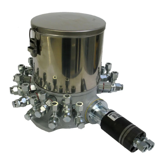
- Page 1 Multi-line pump unit Type GMF-S01 Translation of the original operation manual Version EN 07/2017 GMF-S01 Operation manual Page 1 of 31 B0836...
- Page 2 Unless permitted explicitly, the dissemination, reproduction, and utilisation of this document as well as the communication of its contents are prohibited. Any violation of this stipulation shall involve the obligation to compensate damage. All rights reserved. GMF-S01 Operation manual Page 2 of 31 B0836...
-
Page 3: Table Of Contents
6. Transportation, installation, commissioning and shutdown ........20 Transportation ......................20 Unpacking ......................20 Installation ......................20 Power supply and switch-on ................... 21 6.4.1 Hydraulic motor ...................... 21 6.4.2 Electric motor (option) ..................... 21 Commissioning ....................... 21 GMF-S01 Operation manual Page 3 of 31 B0836... - Page 4 Repair ........................26 Accessories ......................27 9. Return shipment to factory ................... 28 Disposal ........................30 Appendix........................30 11.1 Content of the declaration of conformity..............30 11.2 Declaration of conformity ..................31 GMF-S01 Operation manual Page 4 of 31 B0836...
-
Page 5: Important Notes On This Operation Manual
Should you have any question or uncertainty, contact WOERNER, please. 1.3 What to do in case of questions In case of questions that you cannot solve by means of this operation manual, WOERNER will help you. In such situations it is indispensable that you provide us with a precise description of the problem at stake. -
Page 6: Location
Notes on application and other useful information facilitating the proper usage of the product. Danger! Any danger threatening immediately due to the presence of electric current that may cause serious personal injuries. GMF-S01 Operation manual Page 6 of 31 B0836... -
Page 7: Identification
2. Identification 2.1 Product brand and type designation Piston pump unit manufactured by Eugen Woerner GmbH & Co. KG Product type: GMF-S01 2.2 Product version Version as of model year 2015 2.3 Product marking The type label is located at the side of the pump body and contains information as follows:... -
Page 8: Product Description
+80 °C Relative humidity: max. 70% Noise level: <70 dB(A) Physical environment In heights as of 1.000 metres above sea level, the system should be operated after consultation with the manufacturer only. GMF-S01 Operation manual Page 8 of 31 B0836... -
Page 9: Conventional Usage
0,5 bar, as well as that of highly inflammable or explosive media and foodstuff is prohibited! Important! Please also note the safety data sheets pertaining to the materials used! 3.5 Technical data 3.5.1 Assemblies The GMF-S01 pump unit consists of three assemblies: Pump body with pump elements Reservoir ... -
Page 10: Dimensions
3.5.2 Dimensions The dimensions of the GMF-S01 multi-line pump are as follows: for electric with hydraulic motor Reservoir Width B Depth T Height H motor max. weight capacity max. weight (without lubricant, (without lubricant) without electric motor) 31,3 kg 22,8 kg... -
Page 11: Multi-Line Pump Unit Technical Data
3.5.3 Multi-line pump unit technical data The GMF-S01 comprises the pump body with the pump elements, a mounted reservoir, and a hydraulic motor. The unit’s technical data is as follows: 1 … 24 Number of pump elements Delivery volume per stroke per pump element 6 0,08 cm³... -
Page 12: Functional Description
The technical specifications of the electric motor, please refer to the type plate, which is mounted on the electric motor. Functional description 4.1 Components Hopper reservoir Pump casing Stirring unit Stirring wing Pump shaft Pressure ring Worm wheel Worm Pump element Hydraulic motor GMF-S01 Operation manual Page 12 of 31 B0836... -
Page 13: Drive
3 and the lubricant is delivered by the delivery piston to the outlet. Pump element 8 is marked by a red ring R. GMF-S01 Operation manual Page 13 of 31 B0836... -
Page 14: Safety Notes
Work on electric facilities may be performed by skilled electricians in conform- ity with DIN VDE 1000-10 only. For the planning and inspection of the work, professionals with product-specific training are responsible. GMF-S01 Operation manual Page 14 of 31 B0836... -
Page 15: Safety Facilities
In normal use both fasteners must be closed. If it´s necessary to open the lid it is mandatory to follow the instructions below. Always ensure that the pump is switched off before opening the lid! GMF-S01 Operation manual Page 15 of 31 B0836... - Page 16 After safety latch is unlocked, lift the locking lever and release the locking lug from the locking hook to fully unlock the fastener. Step 3: Repeat step 1 and 2 for the second fastener. GMF-S01 Operation manual Page 16 of 31 B0836...
-
Page 17: Accident Prevention
Prevent unauthorised persons from accessing the pump unit Keep foreign persons away from the areas and places of risk Inform present foreign persons about residual risks repeatedly. Inform yourself about such risks in the "Residual risks" section. GMF-S01 Operation manual Page 17 of 31 B0836... -
Page 18: Residual Risks
It is prohibited to reconstruct or modify the pump unit. The operator should be notified of any fault or damage immediately. For repair, no others than original spare parts may be used. GMF-S01 Operation manual Page 18 of 31 B0836... -
Page 19: Disclaimer
Should any damage be caused to persons, objects, the environment and/or property due to the non-observance of this operation manual, no matter whether intentionally or uninten- tionally, WOERNER shall be held harmless thereof. Besides, all warranty claims will be rejected. The same also applies to any and all consequential damage. -
Page 20: Transportation, Installation, Commissioning And Shutdown
In addition, make sure that the mounting surface is plane. As for the installation the pump unit take necessary prevent measures to protect the unit from unintentional shocks. Drill pattern: Mounting for M8 GMF-S01 Operation manual Page 20 of 31 B0836... -
Page 21: Power Supply And Switch-On
DIN VDE 1000-10. 6.5 Commissioning The pump unit‘s functionality has been checked in the factory. Hence, it is ready for opera- tion and can be connected to a local hydraulic supply. GMF-S01 Operation manual Page 21 of 31 B0836... - Page 22 Check all connections of the lube lines for tightness and the lube points for unobstructed lubricant release. Note that the pump unit, depending on the ambient conditions, is capable of building up maximum pressures of far more than 500 bar! GMF-S01 Operation manual Page 22 of 31 B0836...
-
Page 23: Shutdown
Any pump pressure above the admissible operating pressure of 350 bar may result in the destruction of the system and situations endangering health! 6.6 Shutdown The unit is shut down by switching off and disconnection from the hydraulic supply. GMF-S01 Operation manual Page 23 of 31 B0836... -
Page 24: Operation
Should the above mentioned troubleshooring and the corresponding remedies not lead to a flawless operation of the pump, turn to WOERNER, please. 7.2 Refilling the reservoir If the equipment is operating with oil, refill directly into the reservoir. -
Page 25: Switch-Off
Please note, in particular, the special hazardous spots described in the "Safety regulations" section and take effective measures to avoid injuries. GMF-S01 Operation manual Page 25 of 31 B0836... -
Page 26: Inspection Schedule
Screw the pump element down. Installation and commissioning will be facilitated if the hole of the pump element that serves to accommodate the delivery piston is filled with grease. For other repairs, turn to WOERNER, please. GMF-S01 Operation manual Page 26 of 31... -
Page 27: Accessories
110.568-65 customer’s specification, 50 … 160 bar Pressure control valve, adjusted acc. to 110.562-65 customer’s specification,160 … 250 bar Other accessories Gauge connection, G 1/4 110.068-65K Function display 752.528-69 Adjusting wrench 110.004-65 GMF-S01 Operation manual Page 27 of 31 B0836... -
Page 28: Return Shipment To Factory
The product must be discharged and clean. All openings must be closed. The product must be packed safely and marked completely. The declaration of compliance must be attached. GMF-S01 Operation manual Page 28 of 31 B0836... - Page 29 The relevant safety data sheets are enclosed. Date of return shipment: Name, position: Phone number: Date, signature: Company stamp: Enclosures: Safety data sheet GMF-S01 Operation manual Page 29 of 31 B0836...
-
Page 30: Disposal
11. Appendix 11.1 Content of the declaration of conformity We hereby declare that the product Piston pump type GMF-S01 as of model year 2015 meets all relevant provisions of the directive on machinery (2006/42/EC). Furthermore, the machine complies with all provisions of the directive on electromagnetic compatibility (2004/108/EC). -
Page 31: Declaration Of Conformity
11.2 Declaration of conformity GMF-S01 Operation manual Page 31 of 31 B0836...
Need help?
Do you have a question about the GMF-S01 and is the answer not in the manual?
Questions and answers