
Related Manuals for WOERNER GMF


Summary of Contents for WOERNER GMF
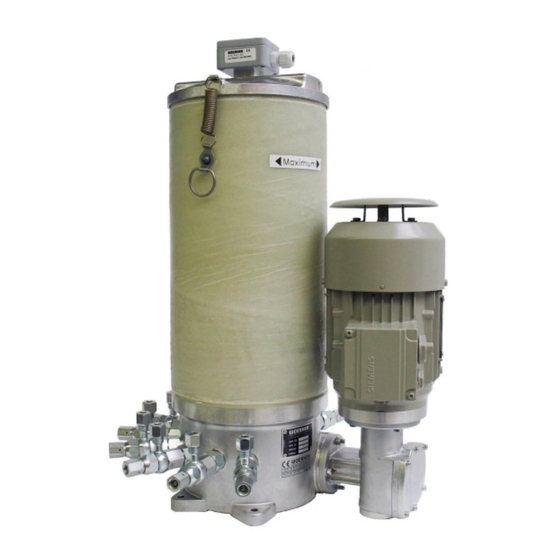
- Page 1 Multi outlet pump unit GMF (with motor) PMF (without motor) Translation of the original operation manual Version EN 02/2019 Operating manual PMF/GMF Page 1 of 37 B0343...
- Page 2 This document shall neither be transferred to third parties nor copied. Its content must neither be commercialized nor communi- cated, if not explicitly allowed. Violating the before mentioned will cause claim for indemnification. All rights reserved. Operating manual PMF/GMF Page 2 of 37 B0343...
-
Page 3: Table Of Contents
Specialities for types built in compliance with the provision 2014/34/EU (ATEX) ..24 6. Transport, installation, start-up and putting out of operation ........25 Transport ........................ 25 Unpacking ......................25 Installation ......................25 Power supply and powering-up ................26 Operating manual PMF/GMF Page 3 of 37 B0343... - Page 4 Accessories ......................33 List of spare parts ....................34 9. Return to manufacturer ....................34 Disposal ........................36 Appendix........................36 11.1 Content of the declaration of conformity..............36 11.2 Declaration of Conformity ..................37 Operating manual PMF/GMF Page 4 of 37 B0343...
-
Page 5: Important Information On This Operating Manual
1.4 Operating manual 1.4.1 Validity This operating manual fits to the series design of the multi outlet pump units GMF and PMF. If some sections of the operating manual refer to some special versions, then it will be espe- cially pointed to. -
Page 6: Site Of Operation
Important! Instructions for use and other useful information that facilitate usage of the product according to its design. Danger! Immediately threatening danger by electric current that may lead to heavy body injuries. Operating manual PMF/GMF Page 6 of 37 B0343... -
Page 7: Identification
2. Identification 2.1 Product mark and type designation Piston pump unit of the manufacturer Eugen Woerner GmbH & Co. KG Product types: GMF and PMF 2.2 Product version Version from the year of production July 2015 2.3 Product denomination The identification plate has been attached to the side of the pump case and informs on:... -
Page 8: Product Description
70% Noise level: <70 dB(A) Physical environment If the equipment is planned to be operated at a level higher than 1,000 m above sea level, consult the manufacturer, in every case. Operating manual PMF/GMF Page 8 of 37 B0343... -
Page 9: Use According To Design
Important! Please consider the safety specification sheets of the applied substances as well! 3.5 Technical data 3.5.1 Components The pump unit GMF consists of 4 components: Pump body Pump elements ... -
Page 10: Dimensions
3.5.2 Dimensions The following drawings depict the dimensions of the multi-outlet pump unit GMF. The dimensions may vary according to type: GMF-A GMF-B GMF-C GMF-D Operating manual PMF/GMF Page 10 of 37 B0343... - Page 11 Reservoir made from special steel Reservoir made from polyester Operating manual PMF/GMF Page 11 of 37 B0343...
- Page 12 10 litres up to 10 litres Reservoir capacity Reservoir capacity 25 and 30 litres 25 and 30 litres Reservoir capacity 25 and 30 litres Drive "V" Drive "O" Drive "R", "U" Operating manual PMF/GMF Page 12 of 37 B0343...
-
Page 13: Weights
0,18 kg Weight of the pump element (PE): 0,3 kg 3.5.4 Pump specification The GMF is made up of the pump case with pump elements, attached reservoir and drive. Technical data of the pump unit: Number of pump elements GMF-A max. -
Page 14: Drive Specification
Power (with oil flow 3,5 l/min) 0,25 kW Speed (with oil flow 3,5 l/min) 400 min Speed max. 1950 min Pressure drop max. 100 bar Oil flow max. 16 l/min Operating manual PMF/GMF Page 14 of 37 B0343... -
Page 15: Filling Level Monitoring Specification
0.5 … 1,5 mm² Wire cross-section Connecting diagram: Reservoir full Reservoir empty When inductive or capacitive loads are to be connected, appropriate protective devices (diode, RC-element, varistor) have to be installed Operating manual PMF/GMF Page 15 of 37 B0343... -
Page 16: Description Of Function
The function of the pump elements will be explained later. An agitator is linked with the pump shaft forcing the lubricant to the suction borehole of the pump ele- ments to comminute air bubbles. Operating manual PMF/GMF Page 16 of 37 B0343... -
Page 17: Pump Elements
As for precise adjustment to a defined delivery volume per stroke, a volumetric prove- measurement has to be taken. The pump elements are delivered adjusted to maxi- mum volumetric displacement. Turn in the plug screw 7. Operating manual PMF/GMF Page 17 of 37 B0343... -
Page 18: Safety Instructions
For planning and inspection of the work, specialists with product-specific training are responsible. 5.3 Safety devices From mechanical aspect, the pump unit is inherently safe due to its design. The pump unit must be operated only with the lid of the reservoir closed. Operating manual PMF/GMF Page 18 of 37 B0343... -
Page 19: Reservoir Lid
If it´s necessary to open the lid it is mandatory to follow the instructions below. Always ensure that the pump is switched off before opening the lid! Description Locking hook Locking lug Safety latch (locked) Safety cover Locking lever Operating manual PMF/GMF Page 19 of 37 B0343... - Page 20 After safety latch is unlocked, lift the locking lever and release the locking lug from the locking hook to fully unlock the fastener. Step 3: Repeat step 1 and 2 for the second fastener. Operating manual PMF/GMF Page 20 of 37 B0343...
- Page 21 Repeat step 1 for the second fastener. Warning! Try if safety latch is snapped in by pulling the locking lever. Lifting the locking lever is not possible if the safety latch is in the locked position. Operating manual PMF/GMF Page 21 of 37 B0343...
-
Page 22: Accident Prevention
Referring to experience, improper use may include, for example: Supply of highly flammable or explosive media. Supply of media, which are able reacting with materials the pump unit has been made of. Supply of foodstuff. Operating manual PMF/GMF Page 22 of 37 B0343... -
Page 23: General Safety Regulations And Duties
If damage to persons, equipment, environment and assets occurs due to ignoring this oper- ating manual regardless if intentionally or unintentionally, WOERNER shall not be held re- sponsible. No claim for warranty will be accepted. This is also true for any consequential damage. -
Page 24: Specialities For Types Built In Compliance With The Provision 2014/34/Eu (Atex)
The drive power must not exceed 0,37 kW. In case of failure and/or faults, get the pump unit checked and repaired by competent personnel or WOERNER themselves. Dismantle the pump unit and handle the single parts exclusively outside of poten- tially explosive areas. -
Page 25: Transport, Installation, Start-Up And Putting Out Of Operation
In addition, make sure that the mounting surface is plane. As for the installation the pump unit take necessary prevent measures to protect the unit from unintentional shocks. Drilling pattern: Operating manual PMF/GMF Page 25 of 37 B0343... -
Page 26: Power Supply And Powering-Up
Link the eccentric with the rocker arm of the pump drive. Before starting-up, check the rocker arm for proper length depending on the eccentric stroke (as for the formula, see section 3.5.5). Important! Improperly set-up rocker arm length may lead to damage of the pump. Operating manual PMF/GMF Page 26 of 37 B0343... -
Page 27: Start-Up
Venting on the pump element For that purpose, switch-on the pump unit with the lubricant feeding lines not installed as many times as necessary to have the lubricant emerging at the outlet without air bubbles. Operating manual PMF/GMF Page 27 of 37 B0343... -
Page 28: Putting Out Of Operation
350 bar may lead to destruction of the installation and health- hazardous situations! 6.6 Putting out of operation The pump unit is put out of operation by switching-off and deinstalling from the external power supply. Operating manual PMF/GMF Page 28 of 37 B0343... -
Page 29: Operating Manual
If the above described trouble shooting guide should not successfully work and the pro- posed remedy does not help eliminating the fault to restore the proper function of the pump unit, please get in contact with WOERNER. Operating manual PMF/GMF... -
Page 30: Refilling The Reservoir
With filling-level control and follow-up piston: Before re-filling the tank, take out the follow-up piston from top and assemble, then! 7.3 Powering down Powering down is by disconnecting the pump unit from the power supply. Operating manual PMF/GMF Page 30 of 37 B0343... -
Page 31: Cleaning, Servicing, Fault Remedy And Repair
Safety instructions. Take effective measures to avoid injuries. Important! Consider also the maintenances instructions for the single com- ponents of the respecting operating manuals collected in the annex. Operating manual PMF/GMF Page 31 of 37 B0343... -
Page 32: Inspection Chart
Screw in the pump element. Fill the borehole of the pump element supporting the displacing pistons with grease to facilitate both assembly and start-up. For any further repair, please contact WOERNER. Operating manual PMF/GMF Page 32 of 37 B0343... -
Page 33: Accessories
110.568-65 50 … 160 bar Pressure relieving valve set to customer’s specification, 110.562-65 160 … 250 bar Additional accessories Gauge port G 1/4 110.068-65K Function display 752.528-69 110.004-65 Adjusting wrench Operating manual PMF/GMF Page 33 of 37 B0343... -
Page 34: List Of Spare Parts
Before shipping the product, make sure that the following measures have been taken: Empty and clean the product. Plug all openings. Pack the product safely and attach complete shipping documents. Attach the declaration of harmlessness. Operating manual PMF/GMF Page 34 of 37 B0343... - Page 35 The respective safety sheets have been attached. Date of return: Name, position: Phone number: Date, signature: Firm stamp: Appendices: Safety data sheet Operating manual PMF/GMF Page 35 of 37 B0343...
-
Page 36: Disposal
11. Appendix 11.1 Content of the declaration of conformity We hereby declare that the product Pump unit GMF as of model year 2015 meets all relevant provisions of the directive on Machinery (2006/42/EC). Furthermore, the machine complies with all provisions of the Directive on Electromagnetic Compatibility (2004/108/EC). -
Page 37: Declaration Of Conformity
11.2 Declaration of Conformity Operating manual PMF/GMF Page 37 of 37 B0343...
Need help?
Do you have a question about the GMF and is the answer not in the manual?
Questions and answers