Advertisement
Available languages
Available languages
Quick Links
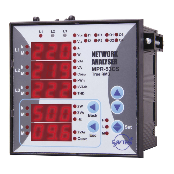
NETWORK ANALYZER
MPR-53CS
General
MPR-53CS measures all the electrical parameters that belong to network. MPR-
53CS is designed for protection of electrical system. Measured parameters are
shown in 5 separate displays. This allows to monitor more than 50 parameters at the
same time. MPR-53CS has also MODBUS serial interface feature.
The table below shows the parameters that are measured by MPR-53CS:
Functions of Buttons
Used for switching between (VLN, VLL, A, W, VAr, VA, Cos
kVarh, THD, C-1, C-2, tot-h, run-h) parameters in the monitoring
mode.
Used for switching between previous ( ) or next ( ) menu in main
menu or submenus and also use for changing chosen values.
(SET) Used for switching between min., max demand and instant
values in the monitoring mode. In display when run hour (run -h) is
displayed, if SET button is pressed, it shows setpoint hours
(SP -h) counted time. In latch function when button feature is used,
with SET button latch position operation is done. Switching to the
programming mode if it pressed for 3 sec. It is used for switching to the
menu and saving changes for the parameters in programming mode.
(Back) Used for switching between SW, SVA and Hz parameters in the
monitoring mode. Used for switching previous digit in submenu.
(ESC) Used for switching between SVAr and Cos
monitoring mode. Used for entering to upper menu or it is used to quit
from the programming mode without saving values in the programming
mode.
When Pin is activated, after pressed "SET" button for 3 seconds, PIN is
required; after entering correct PIN code, you can enter to menu.
Use of MPR-53CS:
By using Up/Down buttons parameters are shown in L1, L2, L3 displays (VLN; VLL;
A; IN; W; VAr; VA; Cosj; kWh, kVarh, THD, C-1, C-2, tot-h, run-h). Total Active (SW),
Total Apparent Power (SVA) and Frequency (Hz) are selected by Back button.
Total Reactive Power (SVAr) and Cos
Digital Inputs
MPR-53CS has 2 digital inputs. Digital inputs have 2 functions :
- If remote control is activated (battery, thermostat, circuit breaker, engines status)
the status of devices connected to digital input will be seen according to datas in
time regiters.
- When digital inputs of energy count, run hour and latch menus are selected, digital
inputs controls these menu's functions (Example: It is used for measuring of energy
separately at the using of network and generator).
aren't any signal in digital inputs. Otherwise "on".
Energy Pulse Outputs
MPR-53CS has 2 energy pulse outputs. Pulse outputs give the pulses only for
E-1 (energy counter). Pulse outputs can be programmed one by one. When pulse
outputs give pulse "P1" (Pulse 1) and "P2" (Pulse 2) lights (Not included in the PK-26
Pul1 ve Pul2 : There are sub menus o-1 (pulse 1) and o-2 (pulse 2) in pulse out
menu. Device gives pulse according to chosen energy parameters [Active energy
(ACt, A-I, A-E), Reactive energy (rEA, r-L, r-C)]. For energy count values, look at
the pulse menu.
Pulse Counter
MPR-53CS has 2 pulse counters (C-1, C-2). C-1 counts the pulses from digital input
1 and C-2 counts the pulses from digital input 2.
Pulse counter detect the pulses which are in condition of signal 1. When the number
of pulses reach "pulse C1/2 ratio" value, releated pulse counter is increase by 1.
When C-1/C-2 counters are not activated in pulse counter menu, instant values of
values in the
are selected by Esc button.
C-1/C-2 are not displayed.
Note: DC signals must be use supplied in order to use this menu.
Digital Outputs
MPR-53CS has 6 digital outputs. Only 2 of them have LED on the front panel. These
are "O-3" and "O-4" LEDs ("O-4" light is not available in the PK-26 box).
When digital outputs are activated, related addresses can be displayed with "xxx"
values, only "O-3" and "O-4" LEDs are lighted for digital outputs 1 and 2 on front
panel. Digital output on devices menu's output parameters; 1/2/3/4/5/6 correspond
to "3/4/5/6/7/8" parameters.
User can check the digital output register for fault about set parameters by
communicating with the device.
Relay Outputs
MPR-53CS has 2 NO contact outputs. On front panel, MPR-53CS has
o-1 and o-2 LEDs. When alarm parameters are selected 1 (out 1) and 2
(out 2) for output, device gives alarm. Related contact outputs will close and LEDs
will be on.
Total Hours
Shows running time of MPR-53CS from the beginning. User can not reset this
counter.
Run Hours
Shows MPR-53CS's running hour. This can be resetted and can be controlled by
it runs if there is a signal in digital inputs. It does not run if there is no signal in digital
inputs.
Setpoint Hours
By pressing SET button during monitoring of Run Hour, set point hour can be
monitored. Setpoint hour runs according to run hour. When run hour runs actively,
setpoint hour runs. When set time value reaches to "hoU r SP" which set by user,
selected output will be active (1) and give an alarm and setpoint hour continues to
count. This alarm can be erased by resetting setpoint hour or getting out from locked
position. When setpoint output is required to remove by using latch function, "latch
auto" function can't be used. If MPR-53CS returned to normal operation from failure
by using latch function, it automatically starts the time from zero. To make setpoint
hour passive, the value of SP hour is set "0000". This setting only closes the setpoint
Note: Total hour and run hour do not count during electric interruptions. Total hour
measurement mode, by scrolling UP and DOWN buttons, user can see running
, kWh,
time. Run hour display is shown is "HH HHH H.HH" (H=Hour) form. All the values
shown on the display are in terms of hour. For example, if displayed value is 00 000
1.75, means that device worked for 1.75 hours. If the user wants to convert last digit
to minutes, last digitx0.6 (75x0.6=45 minutes) formula is used conversion. Device
worked 1 hour 45 minutes.
İmportant: In "hoU r SP" menu when chosen output is activated and devices is set
for giving an alarm at the end of one hour. After counting to 99 on display, devices
gives an alarm (1 hour = 60 min. for MPR-53CS on display "99" corresponds to "59").
Monitoring of Min.- Max. and Max. Demand Values:
If measured instant value is smaller than min. value, they are saved as new min. and
if measured instant value is bigger than instant max. value, new max. value is saved.
During demand time (example 15 min.) demand value is got max. demand.
If press SET button when the device is in any parameter (example "A") min., max.
parameter (example "Cos ") is displayed, the device continues to display instant
parameters.
Monitoring THD Values
If "VLN" and "THD" LED's light on together, voltage "THD" is monitored. And if "A"
and "THD" LEDs light on, current "THD" is monitored.
Monitoring Neutral Current
When instant current values of 3 phases are shown on the display, by pressing the
"DOWN" button, I-n (neutral current) is displayed. "A" LED continues light on. When
connection form is chosen as delta, this display will be closed.
Monitoring Setpoint Parameters Fault Warning
Device activates the selected output if there is a failure because of any causes.
User can set more then one parameters to output, so outputs can be monitored
depending which parameter and this parameters protection type (low, high, both of
them) even in failure situation when "rUn -h" menu is displayed, pushing "DOWN"
button or when VLN is displayed pushing "UP" button, failure parameter will be seen
as "SP -xx h/L/hL x-x x-x". If there is a no failure, you will not see such a display.
After pressing SET button you can see other failure parameter.
Calculation Methods for Active / Reactive Values
If the dot on the right down corner blinks it shows that active power and reactive
powers directions are negative. There are 2 methods for calculating total active and
total reactive powers.
1) Active and reactive powers are calculated by summing import and export values
and shown as a single value.
2) Active and reactive powers are calculated one by one according to import/export
condition.
Note :
1) During W LED is displayed, if the dot at the most right down digit of the forth
display lights on, it represents that displayed value is export active power value.
If not, it represents that displayed value is import active power value.
2) During
display lights on, it represents that displayed value is capacitive reactive power
value. If not, it represents that displayed value is inductive reactive power value.
stand by.
1
, V
, A, W, VAr, VA, W, VAr, VA;
LN
LL
W, VA, VAr.
Advertisement

Related Manuals for Entes MPR-53CS


Summary of Contents for Entes MPR-53CS
- Page 1 5 separate displays. This allows to monitor more than 50 parameters at the MPR-53CS has 6 digital outputs. Only 2 of them have LED on the front panel. These same time. MPR-53CS has also MODBUS serial interface feature.
- Page 2 NETWORK ANALYZER MPR-53CS Current Transformer Ratio Setup: In this menu current transformer ratio is set (There is no in CT-25 “CAL CUL Atı on” menu. models). Current transformer ratio can be set between 1 ..2000. Note: If the current transformer is not used between the system and the device, current transformer ratio is entered as “1”.
- Page 3 UP/DOWN buttons, new data will be cancelled and previous Energy Counter (Eng Cnt) Menu: value will be activated. MPR-53CS has 2 energy counters: Activating User Password : Energy Counter 1 (E-1), Energy Counter 2 (E-2). This menu is used for activating the user password.
- Page 4 NETWORK ANALYZER MPR-53CS Latch menu: Hour menu: When latch function of set parameters is active, user can choose the way In this menu run hour and setpoint hour is set. how to fault recovery in this menu. User can make this by 3 ways.
-
Page 5: Modbus Rtu Protocol
ERROR CODES Press SET button, “rS- 485 Adr ES/bAU d/PAr ıty” is displayed. (Option Slave device (MPR-53CS) sends error message when receive any missing query. is entered but is not activated yet. For activating please follow the below steps) Error codes are given below: 01 Invalid Function: If any message except given above is used, then 01 error Press ESC button one by one, until “SAU E SEt yES”... - Page 6 NETWORK ANALYZER MPR-53CS 31 DEVICES CAN BE CONNECTED AT THE SAME LINE MAX. 247 DEVICES CAN BE CONNECTED AT SAME LINE BY USING REPEATER. PK 26 Box Connection Diagram 3 Phase neutral 3 Phase without neutral 3 Phase without neutral current input with...
- Page 7 NETWORK ANALYZER MPR-53CS PR 19 Box Connection Diagram l: When CT-25 is used, Black cable is connected to l terminal. 3 Phase without neutral current input wşth 3 Phase neutral 3 Phase without neutral current input with 3 Phase without neutral Note: For CT-25 models: k: When CT-25 is used, Red cable is connected to k terminal.
- Page 8 NETWORK ANALYZER MPR-53CS Technical Data Operating Voltage (Un) : Please look behind the device. Operating Frequency (f) : 45-65 Hz Auxiliary supply Power Consumption : < 4 VA Measuring Input Power Consumption : < 1 VA : 10-300 V AC 45-65 Hz. (L-N) : 10-500 V AC 45-65 Hz.
- Page 9 Gesamtstunden: Es zeigt die gesamte Stunden seit der erste Bedienung des Geräts. Es ist nicht rückstellbar beim Benutzer. Run Hours: Shows MPR-53CS’s running hour. This can be resetted and can be digital inputs, it runs if there is a signal in digital inputs. It does not run if there is no signal in digital inputs.
- Page 10 Gerät gespeichert. Um alle die Werte zu löschen; Sie müssen zu “rES Beispiel: Wenn ein 34,5kV/100V Spannungwandler zwischen Et hL/dE/E-1/E-2/C-1/C-2/rUn hoUr/SP hoUr no” Menü eintreten, “yES” dem gemessenen Netz und MPR-53CS benutzt wird, wird das auswählen, von allen Menüs austreten und die Änderungen besätigen. Spannungwandlerverhältnis als 345(34500/100) eingegeben.
- Page 11 Daten befolgen Sie die folgende Schritten). Energiezähler(Eng Cnt) Menü: Drücken Sie auf ESC-Taste bis “SAU E SEt yES” ist angezeigt. MPR-53CS enthält 2 Energiezähler. Energiezähler 1(E-1), Energiezähler 2(E-2). Drücken Sie auf SET-Taste. Während “SAU E SEt yES” ist on: “E-1 / E-2” Zähler sind für eine parameterunabhängige und angezeigt, wenn Sie auf ESC-Taste drücken oder mit AUF- und...
- Page 12 NETZANALYSATOR MPR-53CS Sperrenmenü: Stundenmenü: Dieses Menü wird für die Einstellungen den Betriebsstunden und den Wenn Sperrenfunktion für einen eingestellten Parameter aktiv ist, kann Sollwertstunden benutzt. der Benutzer in diesem Menü die Fehlersbeseitigungsart auswählen. Es “hoUr ACt”: Dieses Menü wird für die Aktivierung den Betriebsstunden gibt 3 Optionen.
- Page 13 NETZANALYSATOR MPR-53CS Drücken Sie auf SET-Taste für 3 Sekunden (trA Fo Menü ist MODBUS RTU PROTOKOLL: engezeigt). Standard MODBUS RTU Protokoll Nachrichtformat ist unten dargestellt. Dieser Wert entspricht einer Zeit(zwischen 3-5 Zeichen-Zeit), in denen keine Drücken Sie auf SET-Taste (“SP -01” Menü ist angezeigt).
- Page 14 NETZANALYSATOR MPR-53CS IN EINER LEITUNG KÖNNEN SIE 31 GERÄTE ANSCHLIESSEN. MIT HILFE EINES REPEATERS KÖNNEN SIE BIS ZU 247 GERÄTE IN SERIE ANSCHLIESSEN. PK 26 Kassenanschlussplan 3 Phasen mit Neutral Anschluss 3 Phasen ohne Neutral Aron-Anschluss 3 Phasen ohne Neutral Anschluss Nur gültig für MPR-53S.
- Page 15 NETZANALYSATOR MPR-53CS PR 19 Kassenanschlussplan 3 Phasen mit Neutral Anschluss 3 Phasen ohne Neutral Aron-Anschluss 3 Phasen ohne Neutral Anschluss 3 Phasen ohne Neutral Aron-Anschluss Nur gültig für MPR-53S. k: Wenn CT-25 benutzt ist, rotes Kabel ist an der Klemme “k” angeschlossen.
- Page 16 Der Hersteller oder eine von seiner Tochtergesellschaften übernimmt A4396/Rev.3 keine Verantwortung für die Folgen, die sich aus der Nichteinhaltung dieser obener Anweisungen entstehen. 01.03.2021 ENTES Elektronik Cihazlar Imalat ve Ticaret A.S. Adr: Dudullu OSB; 1. Cadde; No:23 34776 Ümraniye - İSTANBUL / TÜRKİYE Tel:...
Need help?
Do you have a question about the MPR-53CS and is the answer not in the manual?
Questions and answers