Table of Contents
Advertisement
Quick Links
VOLTAGE MONITORING
EVM-05C
Connection Diagram................................................................................
Precautions For Installation And Safe Use...................................................
Front Panel And Usage of Buttons............................................................
General Information...............................................................................
Properties..............................................................................................
Specific Functions of Buttons...............................................................
................................................................................
High And Low Setpoints
High And Low Setpoints For 1st Phase
High And Low Setpoints For 3rd Phase
Hysteresis Values For High And Low Setpoints
Delay-On Time For High And Low Setpoints
Frequency Setpoints Menu
Phase Sequence Menu........................................................................
Latch Function Menu.............................................................................
Instant Tripping Menu............................................................................
Voltage Transformer Ratio Menu...........................................................
Connection Type Settings Menu...........................................................
Clearing Max And Min.Values Menu......................................................
User Password Menu............................................................................
Technical Specifications...........................................................................
Connection Diagram
1
2 3 4
Out 2
Out 1
Relay Output
Voltage Measuring
Auxiliary
Input
Supply
U n
~
L1
L2
N
L3
5
6
7
8
9
10
L1
L2
L3
N
PR-19
Auxiliary
Voltage Measuring
Supply
Input
U n
~
L1
L2
L3
N
L1
L2
L3
N
PK-26
Precautions For Installation And Safe Use
- Failure to follow those instructions will result in death or serious injury.
- Disconnect all power before working on equipment.
- When the device connected to the network, do not remove the front panel
- Do not try to clean the device with solvent or the like.Only clean the device
with dried cloth.
- Verity correct terminal connections when wiring.
- Electrical equipment should be serviced only by your component seller.
- Only for rack panel mounting.
- The fuse should be used F type and should be 1A
No responsibility is assured by the manufacturer or any of its
subsidiaries for any consequences arising out of the use of this
material.
INDEX
..............................................
.............................
..........................
.............................
.....................
..................................................
32 31 30 29 28 27 26 25
NO
NO
Relay Output
Out 1
Out 2
Voltage Measuring
Input
L1 L2 L3 N
1
2
3 4
L1
L2
System
L3
N
PR-16
Out 1 Out 2
Relay Output
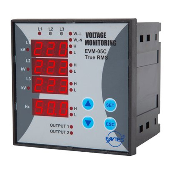
Front Panel And Usage of Buttons
1
1
1
2
2
2
2
2
3
3
3
.......
3
...........
4
4
5
6
8
6
7
7
7
7
8
8
24
23
1... Phase LEDs:The LEDs turn on when all phases are connected to
the system and correct phase sequence.(If phase sequence warning
Auxiliary
is activated and there is a false phase sequence,these LEDs blink.)
Supply
U n
2... kV LEDs of 1.Display: If this LED turns on, the unit of voltage is kV
~
13 14
3... Display of L-1 Phase:It shows L-1 phase-neutral voltage and L1-L2
phase-phase voltage.
4... kV LEDs of 2.Display: If this LED turns on, the unit of voltage is kV
System
5... Display of L-2 Phase:It shows L-2 phase-neutral voltage and L2-L3
phase-phase voltage.
6... kV LEDs of 3.Display: If this LED turns on, the unit of voltage is kV
7... Display of L-3 Phase:It shows L-3 phase-neutral voltage and L3-L1
phase-phase voltage.
8... Frequency Display:The frequency is measured from L-1 phase
9... Output Relay 2 LED
10...Output Relay 1 LED
11...Low Frequency Warning LED
12...High Frequency Warning LED
13...ESC Button
14...DOWN Button
15...SET Button
16...UP Button
17...Low Voltage Warning LED of L-3 Phase (Low voltage warning of L3-
L1 when phase-phase measurement is selected)
System
18...High Voltage Warning LED of L-3 Phase (High voltage warning of L3-
L1 when phase-phase measurement is selected)
19...Low Voltage Warning LED of L-2 Phase (Low voltage warning of L2-
L3 when phase-phase measurementis selected)
20...High Voltage Warning LED of L-2 Phase (High voltage warning of L2-
L3 when phase-phase measurementis selected)
21...Low Voltage Warning LED of L-1 Phase(Low voltage warning of L1-
L2 when phase-phase measurement is selected)
22...High Voltage Warning LED of L-1 Phase(High voltage warning of L1-
L2 when phase-phase measurement is selected)
23...V L-N LED: Phase-Neutral Voltage
24...V L-L LED: Phase-Phase Voltage
1
1
2
3
4
5
6
7
8
9
10
3
2
5
4
12
11
22 21
20 19
18 17
10
9
24
23
22
21
20
19
18
17
15
16
12
13
11
14
7
6
1
16
14
15
13
Advertisement
Table of Contents

Subscribe to Our Youtube Channel
Related Manuals for Entes EVM-05C


Summary of Contents for Entes EVM-05C
-
Page 1: Table Of Contents
VOLTAGE MONITORING EVM-05C Front Panel And Usage of Buttons INDEX Connection Diagram................Precautions For Installation And Safe Use........... Front Panel And Usage of Buttons............General Information................Properties....................Specific Functions of Buttons............... Setpoints ................(SP Menu) High And Low Setpoints .......... -
Page 2: General Information
Application of EVM-05C Hi L-1: L1-L-2 phase phase voltage:433 V 1-) It can measure voltage for each phase and frequency in 3 phase Hi L-2: L2-L-3 phase phase voltage:441 V systems with neutral and without neutral. -
Page 3: (Hi L-1, Lo L-1 Menus)
VOLTAGE MONITORING EVM-05C SETTING HIGH/LOW SETPOINT VALUE FOR PHASES Hi L-1 Menu (High Setpoint for L-1) Press SET button for The max. voltage value that is requested for L-1 phase in star 3 secs. connection and for L-1 L-2 phase-phase in delta connection Find SP menu by The voltage value can be adjusted 0…300 V in star connection. -
Page 4: (Hi Ond, Lo Ond Menus)
VOLTAGE MONITORING EVM-05C Hi Ond Menu (Delay-On Time For High Setpoint) Hi Ofd Menu (Delay-Off Time For High Setpoint) The delay time for activating the output relay for high voltage The delay time for releasing the output relay for high voltage warning.It is common for all phase-neutral and phase-phase... -
Page 5: (Sp Frq Menüsü)
VOLTAGE MONITORING EVM-05C SP Frq Menu (Setpoints For Frequency) Frq Hys Menu (Hysteresis For Frequency) The frequency of the system is measured from L-1 The required frequency value for releasing the output relay If the frequency of system is under the high set value (Frq... -
Page 6: Phase Sequence Menu
Find LATCH menu by scrolling UP/DOWN buttons. PHASE SEQUENCE Press SET button.(LATCH of is displayed.) EVM-05C checks phase sequence.If the phase sequence is altered by any reason, L1 L2 L3 LEDs blink, the output relay 2 activates immediately and Out 2 LED turns off.Factory default... -
Page 7: Instant Tripping Menu
VOLTAGE MONITORING EVM-05C INSTANT TRIPPING FUNCTION CONNECTION TYPE OF SYSTEM At position ON:If any voltage of phase-neutral or phase-phase Con: The menu that is selected the connection type of or frequency exceed 1.5 times of set value,the output relay 1 is activated without any delay time, out 1 LED turns off and system. -
Page 8: User Password Menu
VOLTAGE MONITORING EVM-05C CHANGING USER PASSWORD ACTIVATING USER PASSWORD Press SET button for 3 secs. Press SET button for 3 secs. Find Pin menu by scrolling UP/DOWN Find Pin menu by scrolling UP/DOWN buttons. buttons. Press SET EVM-05C Press SET button(Pin Act is displayed)
Need help?
Do you have a question about the EVM-05C and is the answer not in the manual?
Questions and answers