
Subscribe to Our Youtube Channel
Related Manuals for Entes DCV-10


Summary of Contents for Entes DCV-10
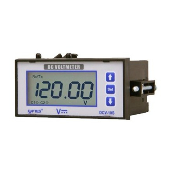
- Page 1 DC VOLTMETER DCV-10 / 10A / 10C / 10S / 10CS / 11 / 11A / 11C / 11S / 11CS User Manual and Menu Map www.entes.de A4741 / Rev.1...
- Page 2 Warnings ATTENTION - Disconnect all power before connecting the device. - Connect a button or a circuit breaker between the grid and the supply inputs of the device. - Don’t remove the front panel while the device is connected to the network. - This button or circuit breaker must be in close proximity of the device.
- Page 3 600 s. - The device provides flexible usage with wide supply voltage range. 85-265 V AC/DC (DCV-10/10A/10C/10S/10CS), 10-56V DC (DCV-11/11A/11C/11S/11CS ) - The device settings can be protected from changes by unauthorized personnel by specifying a 4 digit user password.
- Page 4 Usage of Front Panel and Buttons 1.3 FRONT PANEL 1. Up button The device has a back-lit 2.5” LCD which contains two lines as numeric and alpha-numeric, warning 2. Set button, for entry to menu and value entry symbols and notification signs. There are three buttons for programming the device. Explanations 3.
- Page 5 Note: In order for a change that you committed in the menu to be in effect, you must give approval - RS-485 connector (4-Pin)(DCV-10S/10CS/11S/11CS) for those changes when exiting the menu. Otherwise, changes will not be in effect. - 2 Relay connectors ( 4-pin)(DCV-10C/10CS/11C/11CS) - Supply input (2-pin) (85-265V AC/DC (DCV-10/10A/10C/10S/10CS), 10-56V DC (DCV-11/11A/11C/11S/11CS))
- Page 6 MAIN MENU FLOW: 2.2.1 “PERIOD” Period Setting Menu After the device samples for a specified time, it displays the measurement result by calculating the mean value of those samples. You can set the sampling time in this menu. Period value can be entered between 1-600 seconds.
- Page 7 “ALARM1”Alarm 1 Setting Menu “CONTCT POS” Contact Position Setting Menu Operating mode of the relay on the device and the parameter according to that operating mode is set The starting position of the alarm relay output is set in this menu. If this option is selected as “OFF”, in this menu.
- Page 8 When the alarm type is selected as High Alarm, first contact output opens after an on-delay time (“H HIGH ALARM ON DEL”) if the measured voltage becomes more than the entered maximum voltage value (“HGH “HGH VALUE” VALUE”) and immediate opening option is inactive. In this case, up segment on the LCD and the dot The highest value that you want the measured voltage to reach is entered in this menu.
- Page 9 “H OFF DEL” “L ON DEL” It is the delay time for the high voltage alarm to deactivate. The value is entered as seconds. It can be It is the delay time for the low voltage alarm to activate. The value is entered as seconds. It can be entered between 000.0 and 999.9 seconds.
- Page 10 2.2.3 “ANLG OUT” Analog Output Setting Menu TRIP “ANLG OUT” The device can give a voltage or current output with respect to the measured voltage according to your TRIP TRIP selection. Analog output value can be selected as 0-10V, 2-10V, 0-20mA or 4-20mA. The user can set the analog output type, turn off the analog output, learn the active analog output type or set the minimum and maximum values which the device will take into consideration when generating an analog output.
- Page 11 “HIGHEST” 2.2.4 “RS-485” Serial Communication Setting Menu The voltage value corresponding to the maximum value of the selected analog output type is set in All measured parameters can be transferred via RS485 line with MODBUS protocol and menus can be set this menu.
- Page 12 “BAUDRATE” Baudrate Settings MODBUS RTU PROTOCOL Enter one of the 2400 bps, 4800 bps, 9600 bps, 19200 bps, 38400 bps values as stated in the Standart MODBUS RTU message is shown below. communication software. ADDRESS FUNCTION DATA CRCH CRCL Selected 8 BIT 8 BIT N x 8 BIT...
- Page 13 Read device info (2BH) function is used to learn the manufacturer name, the device code, hardware version Read Hold (03H) function is used for reading the measured parameter (intantenaous measurement and software version. The query packet to read the device info is as following: value, minimum and maximum measurement values) and other setting values of the device.
- Page 14 “RESET MIN” Minimum Value Reset Menu 2.2.6 “DISPLYSET” Display Setting Menu It is the menu where stored minimum voltage value is deleted. Settings about the device display are done in this menu. Display setting menu has 2 sub-menus: “BACKLIGHT”, “CONTRAST”. RESET MIN RESET MIN RESET MIN...
- Page 15 “CONTRAST” 2.2.8 “FCTRY SET” Factory Setting Menu Contrast Setting Menu Factory settings are loaded in this menu. A 4 digit password is asked when entering this menu. If password Contrast of the device display is set in this menu. It can be set to a value between “00” and “15”. protection is active, the password isn’t asked again when entering this menu because it was entered during entering the main menu.
- Page 16 2.2.9 “SECURITY” Security Setting Menu “CHNG PASS” Change Password Menu Device password settings are done in this menu. There are 2 sub-menus under SECURITY menu. Password is changed in this menu. “PASS ACTV”, “PASS CHNG”. Password activation and changing operations are done under these menus.
- Page 17 TYPE PR 20 (48x96) TYPE PR 20 (48x96) Control Panel Area Dimensions Wall 200V DC 54mm Only for DCV-10C/10CS/11C/11CS Only for DCV-10A/11A Only for DCV-10S/10CS/11S/11CS **** Only for DCV-11/11A/11C/11S/11CS 50mm 63mm ***** DCV-10/10A/10C/10S/10CS 85-265V AC/DC, DCV-11/11A/11C/11S/11CS 10-56V DC TYPE PR 20 (48x96)
- Page 18 3.3. PC CONNECTION 4. FACTORY DEFAULT VALUES: Alarms:(DCV-10C/10CS/11C/11CS) MAX. 31 DEVICES CAN BE CONNECTED ON THE SAME LINE 1.Alarm: Alarm Status : Passive MAX. 1200 mt. RS-485 / RS-232 Latch : Off Converter Trip : Off Contact Position (Output Inverse) : Off Alarm Type : High Alarm...
- Page 19 High Alarm On Delay (d_on_time) : 20s 10-56V DC (DCV-11/11A/11C/11S/11CS) High Alarm Off Delay (d_off_time) : 10s Frequency :50/60 Hz (DCV-10/10A/10C/10S/10CS) Low Alarm On Delay (d_on_time) : 20s Supply Input Power Consumption :< 4 VA Low Alarm Off Delay (d_off_time)
- Page 20 Ambient Temperature : -20 ... 70°C 6. REGISTER TABLE: Display : 2.5 inches Backlit LCD 16 Bit Register Table Dimensions : PR-20 Device Protection Class : Double Insulation - Class II ( ) Description Range Unit Multiplier Format Casing Protection Class : IP 40 Terminal Protection Class : IP 00...
- Page 21 Description Range Unit Multiplier Format Range Unit Multiplier Format Description Alarm 1 Alarm 1 Low Alarm Contact Position second ON Delay Normal Alarm 1 Inverted Low Alarm Alarm 1 OFF Delay second Alarm Type Alarm 2 Activation High Protection Active Protection Inactive Low Protection Active Protection Active...
- Page 22 Unit Description Range Multiplier Format Range Unit Multiplier Format Description b0: 0 Relay 1 open Alarm 2 b0: 1 Relay 1 closed High Warning Value b2: 0 Relay 1 High Alarm Fault Alarm 2 b2: 1 Relay 1 Low Alarm Fault Low Warning Value b3: 0 Relay 1 High Alarm ON delay doesn’t count Alarm 2...
- Page 23 Unit Description Range Multiplier Format Unit Description Range Multiplier Format Analog Output Backlight Status Type/Range Backlight Off 0 OUTPUT INACTIVE Backlight On continuously 1 OUTPUT TYPE VOLT RANGE = 0-10 V Backlight On for 30 seconds 2 OUTPUT TYPE VOLT RANGE = 2-10 V Backlight On for 1 minute 3 OUTPUT TYPE CURRENT RANGE = 0-20 mA Backlight On for 5 minutes...
- Page 24 DEVICE ID 7. MENU MAP DEVICE ID && VERSION NO If password is displayed if password is active. is wrong. PASSWORD PASSWORD PASSWORD SERIAL NO 024.00 ERROR If password is inactive. If password is correct. DEVICE ID DEVICE TYPE DEVICE ID DEVICE TYPE DEVICE ID DEVICE TYPE DEVICE ID DEVICE TYPE...
- Page 25 Only valid for DCV-10C/10CS/11C/11CS. ALARM STAT ALARM STAT ALARM STAT ALARM1 BACK MENU Selected parameter is displayed. ALARM 2 CNTCT POS CNTCT POS CNTCT POS It returns to one from which alarm setting is returned. ALRM TYPE ALRM TYPE ALRM TYPE ALRM TYPE HIGH Selected parameter is displayed...
- Page 26 Only valid for DCV-10A/11A. Only valid for DCV-10S/10CS/11S/11CS. RS 485 ADDRESS BACK MENU BAUDRATE PARITY ANLG OUT ANLG OUT NONE 9600 0-20 ANLG OUT Last entered value is displayed. ADDRESS BAUDRATE PARITY HIGHEST HIGHEST HIGHEST ANLG OUT Last entered value is displayed. LOWEST LOWEST LOWEST...
- Page 27 Selected parameter is displayed RESET RESET MIN RESET MAX BACK MENU LANGUAGE LANGUAGE LANGUAGE RESET MIN RESET MAX If password is inactive. If password is wrong. ENTR PASS ENTR PASS FCTRY SET ENTR PASS ERROR If password is correct. If password is active. FCTRY SET SETTINGS DONE...
- Page 28 If password is correct. SECURITY PASS ACTV PASS CHNG BACK MENU OLD PASS OLD PASS NEW PASS NEW PASS If password is wrong. If password is wrong. If password is wrong. ENTR PASS OLD PASS AGAIN ENTR PASS ENTR PASS ERROR ERROR ERROR...
Need help?
Do you have a question about the DCV-10 and is the answer not in the manual?
Questions and answers