Sign In
Upload
Download
Table of Contents
Contents
Add to my manuals
Delete from my manuals
Share
URL of this page:
HTML Link:
Bookmark this page
Add
Manual will be automatically added to "My Manuals"
Print this page
×
Bookmark added
×
Added to my manuals
Manuals
Brands
Entes Manuals
Measuring Instruments
MPR-4 Series
User manual
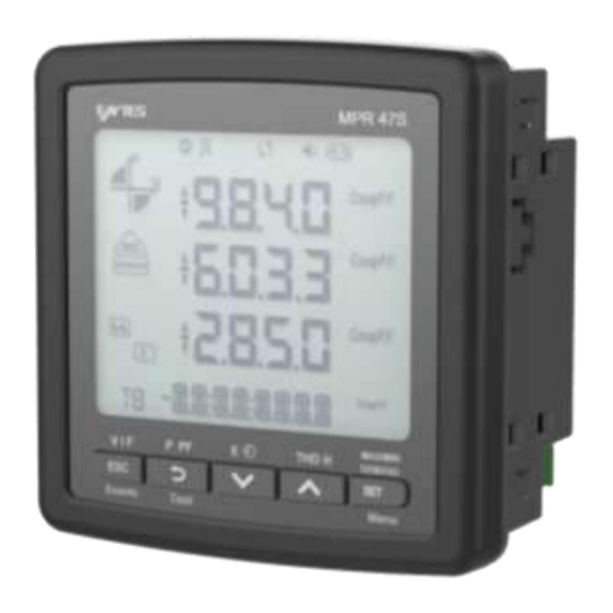
Entes MPR-4 Series User Manual
Network analyzer
Hide thumbs
Also See for MPR-4 Series
:
User manual
(56 pages)
1
Table Of Contents
2
3
4
5
6
7
8
9
10
11
12
13
14
15
16
17
18
19
20
21
22
23
24
25
26
27
28
29
30
31
32
33
34
35
36
37
38
39
40
41
42
43
44
45
46
47
48
49
50
51
52
53
54
55
56
57
58
59
60
61
62
63
64
65
66
67
68
69
70
page
of
70
Go
/
70
Contents
Table of Contents
Bookmarks
Table of Contents
Table of Contents
Safety and Warnings
Warning
Safety
Warranty
Operating Conditions
Introduction
General Features
Applications
MPR-4X Series Product
Overview and Interface
Terminals
MPR-4X Series Rear Panel
MPR-4X-OG/OGT Series Rear Panel
MPR-4X-PM Series Rear Panel
Screen
Button Functions
Terminal Structure
Connection
3P4W (Three Phase Four Wires) Connection
3P3W (3 Phase 3 Wires) Connection
Aron Without Neutral Connection
3P4W BLN (3 Phase Balanced with Neutral) Connection
3P3W BLN (3 Phase Balanced Without Neutral) Connection
Connection Test
Operating Instructions
Measurement Screens
Current, Voltage and Frequency Screens
Power and Power Factor Screens
Energy and Time Screen
THD and Harmonics Screens (MPR-46X, MPR-47X Ve MPR-42-OGT)
Minimum, Maximum and Demand Screens
Ethernet Parameter Displaying Screens (MPR-4XSE)
Setup Screen
Device Installation Settings
Display Settings
Time Settings
RS-485 Communication Settings
Ethernet Communcation Systems
Input Parameter Settings
Output Parameter Settings
Recording Settings
Selecting Parameter to be Recorded
Pulse Input Settings
Pulse Output Settings
Operating Hours Settings
Alarm Settings
Tariff Settings
Reset Settings
System Settings
Analog Output Settings
Reporting Screen
Technical Features and Appendix
Advertisement
Quick Links
1
Table of Contents
2
Warning
3
Rs-485 Communication Settings
Download this manual
MPR-4X
MPR-4X-OG/OGT
MPR-4X-PM
Series
Network Analyzer
User Manual
www.entes.eu
1
1
Table of
Contents
Previous
Page
Next
Page
1
2
3
4
5
Advertisement
Table of Contents
Need help?
Do you have a question about the MPR-4 Series and is the answer not in the manual?
Ask a question
Questions and answers
Related Manuals for Entes MPR-4 Series
Measuring Instruments Entes MPR-4 Series User Manual
Network analyzer (56 pages)
Measuring Instruments Entes MPR-45 User Manual
Mpr-4 series, network analyzer (65 pages)
Measuring Instruments Entes MPR-53S Manual
Network analyser (5 pages)
Measuring Instruments Entes MPR-32 User Manual
Mpr-3 series. network analyser (51 pages)
Measuring Instruments Entes MPR-3 Series User Manual
Network anayzer (53 pages)
Measuring Instruments Entes MPR-1 Series User Manual
Network analyzer (21 pages)
Measuring Instruments Entes MPR-14S User Manual
Network analyzer (21 pages)
Measuring Instruments Entes MPR-53CS Manual
Network analyzer (16 pages)
Measuring Instruments Entes MPR-47SE User Manual
Network analyzer (70 pages)
Measuring Instruments Entes DCA-10 User Manual And Menu Map
Dc ammeter (28 pages)
Measuring Instruments Entes EVM-3 Quick User Manual
Digital voltmeter (2 pages)
Measuring Instruments Entes EMG Series Manual
(28 pages)
Measuring Instruments Entes ES3 Series User Manual
3 phase energy meter (35 pages)
Measuring Instruments Entes EPM-4A Manual
Ammeter (2 pages)
Measuring Instruments Entes EVM-05C Quick Start Manual
Voltage monitoring (8 pages)
Measuring Instruments Entes DCV-10 User Manual
Dc voltmeter (28 pages)
This manual is also suitable for:
Mpr-4 og series
Mpr-4 ogt series
Mpr-4 pm series
Mpr-45
Mpr-45s
Mpr-46
...
Show all
Mpr-46s
Mpr-46s-pm
Mpr-47s
Mpr-47s-0,5
Mpr-47s-pm
Mpr-47se
Mpr-47se-0,5
Mpr-47s-d
Mpr-47s-d-0,5
Mpr-42-ogt-26
Mpr-42-ogt-26-0,5
Mpr-47s-og
Mpr-47s-og-d
Mpr-47s-og-d-0,5
Table of Contents
Print
Rename the bookmark
Delete bookmark?
Delete from my manuals?
Login
Sign In
OR
Sign in with Facebook
Sign in with Google
Upload manual
Upload from disk
Upload from URL


Need help?
Do you have a question about the MPR-4 Series and is the answer not in the manual?
Questions and answers