Sign In
Upload
Download
Table of Contents
Contents
Add to my manuals
Delete from my manuals
Share
URL of this page:
HTML Link:
Bookmark this page
Add
Manual will be automatically added to "My Manuals"
Print this page
×
Bookmark added
×
Added to my manuals
Manuals
Brands
Entes Manuals
Measuring Instruments
MPR-1 Series
User manual
Entes MPR-1 Series User Manual
Network analyzer
Hide thumbs
1
Table Of Contents
2
3
4
5
6
7
8
9
10
11
12
13
14
15
16
17
18
19
20
21
page
of
21
Go
/
21
Contents
Table of Contents
Bookmarks
Table of Contents
Table of Contents
Safety and Warning
Attention
Safety
Operating Conditions
Introduction
General Specifications
Applications
MPR-1 Product Family
Appearance and Interface
Terminal Structures
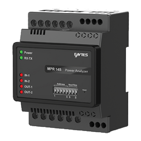
Structure of the MPR-14S Terminal
Structure of the MPR-15S-22 Terminal
Structure of the MPR-16S-21 Terminal
Structure of the MPR-17S-23 Terminal
Connection Types
3P4W (Three-Phase Four-Wire) Connection
3P3W (Three-Phase Three-Wire) Connection
ARON Connection
3P4W BLN (Three-Phase Four-Wire Balanced) Connection
3P3W BLN (Three-Phase Three-Wire Balanced) Connection
Communication Line Termination Resistance
Device Communication Settings
Technical Information and Attachments
Technical Information
IEC 61557-12 Properties
Compliance with the Standards
Advertisement
Quick Links
Download this manual
MPR-1X
Series
Network Analyzer
User Manual
1
www.entes.eu
Table of
Contents
Previous
Page
Next
Page
1
2
3
4
5
Advertisement
Table of Contents
Need help?
Do you have a question about the MPR-1 Series and is the answer not in the manual?
Ask a question
Questions and answers
Related Manuals for Entes MPR-1 Series
Measuring Instruments Entes MPR-53S Manual
Network analyser (5 pages)
Measuring Instruments Entes MPR-45 User Manual
Mpr-4 series, network analyzer (65 pages)
Measuring Instruments Entes MPR-4 Series User Manual
Network analyzer (56 pages)
Measuring Instruments Entes MPR-4 Series User Manual
Network analyzer (70 pages)
Measuring Instruments Entes MPR-32 User Manual
Mpr-3 series. network analyser (51 pages)
Measuring Instruments Entes MPR-3 Series User Manual
Network anayzer (53 pages)
Measuring Instruments Entes MPR-14S User Manual
Network analyzer (21 pages)
Measuring Instruments Entes MPR-53CS Manual
Network analyzer (16 pages)
Measuring Instruments Entes MPR-47SE User Manual
Network analyzer (70 pages)
Measuring Instruments Entes DCA-10 User Manual And Menu Map
Dc ammeter (28 pages)
Measuring Instruments Entes EVM-3 Quick User Manual
Digital voltmeter (2 pages)
Measuring Instruments Entes EMG Series Manual
(28 pages)
Measuring Instruments Entes ES3 Series User Manual
3 phase energy meter (35 pages)
Measuring Instruments Entes EPM-4A Manual
Ammeter (2 pages)
Measuring Instruments Entes EVM-05C Quick Start Manual
Voltage monitoring (8 pages)
Measuring Instruments Entes DCV-10 User Manual
Dc voltmeter (28 pages)
This manual is also suitable for:
Mpr-14s
Mpr-15s-22
Mpr-16s-21
Mpr-17s-23
Mpr-14s-d
Mpr-15s-22-d
...
Show all
Mpr-16s-21-d
Mpr-17s-23-d
Table of Contents
Print
Rename the bookmark
Delete bookmark?
Delete from my manuals?
Login
Sign In
OR
Sign in with Facebook
Sign in with Google
Upload manual
Upload from disk
Upload from URL


Need help?
Do you have a question about the MPR-1 Series and is the answer not in the manual?
Questions and answers