Table of Contents
Advertisement
Quick Links
MPR-4 SERIES NETWORK ANALYSER
INDEX
SAFETY AND WARNINGS ............................................................................................. 3
Warning ....................................................................................................................... 3
Safety .......................................................................................................................... 3
Warranty ...................................................................................................................... 3
OPERATING CONDITIONS ............................................................................................ 4
INTRODUCTION ............................................................................................................. 5
General Features ......................................................................................................... 5
Applications ................................................................................................................. 6
MPR-4 Series Products ............................................................................................... 6
Overview ...................................................................................................................... 6
Terminals ................................................................................................................. 7
Front Panel .............................................................................................................. 7
Button Functions .......................................................................................................... 8
Terminal Structure ....................................................................................................... 9
INSTALLATION ............................................................................................................. 10
3P4W (3 Phase with Neutral) Connection ................................................................. 10
3P3W (3 Phase without Neutral) Connection ............................................................ 10
Aron without Neutral Connection ............................................................................... 11
3P4W BLN (3 Phase Balanced with Neutral) Connection .......................................... 11
3P3W BLN (3 Phase Balanced without Neutral) Connection ..................................... 12
CONNECTION TEST ................................................................................................ 13
Line Termination Resistor .......................................................................................... 13
OPERATING INSTRUCTIONS ..................................................................................... 14
Measurement Screens ............................................................................................... 14
Current, Voltage and Frequency Screens .............................................................. 14
Power and Power Factor Screens.......................................................................... 16
Energy and Time Screens ...................................................................................... 18
THD and Harmonics Screens................................................................................. 21
Minimum, Maximum and Demand Screens ........................................................... 22
Setup Screen ............................................................................................................. 28
Device Installation Settings .................................................................................... 28
Display Settings ..................................................................................................... 32
Time Settings ......................................................................................................... 33
RS-485 Communication Settings ........................................................................... 35
Input Parameter Settings ....................................................................................... 36
Output Parameter Settings ..................................................................................... 38
Recording Settings ................................................................................................. 39
Pulse Input Settings ............................................................................................... 42
Pulse Output Settings ............................................................................................ 43
Operating Hours Settings ....................................................................................... 45
Alarm Settings ........................................................................................................ 46
Tariff Settings ......................................................................................................... 50
Reset Settings ........................................................................................................ 51
System Settings ..................................................................................................... 54
USER MANUAL
1
Advertisement
Table of Contents

Subscribe to Our Youtube Channel
Related Manuals for Entes MPR-45


Summary of Contents for Entes MPR-45
-
Page 1: Table Of Contents
MPR-4 SERIES NETWORK ANALYSER USER MANUAL INDEX SAFETY AND WARNINGS ..................... 3 Warning ........................3 Safety .......................... 3 Warranty ........................3 OPERATING CONDITIONS .................... 4 INTRODUCTION ......................5 General Features ......................5 Applications ......................... 6 MPR-4 Series Products ....................6 Overview ........................ - Page 2 Analog Output Settings ..................57 Reporting Screen ....................... 60 TECHNICAL FEATURES AND APPENDIX ..............62 Technical Features ....................62 Measurement Menu Map 1 ..................64 Measurement Menu Map 2 ..................65...
-
Page 3: Safety And Warnings
SAFETY AND WARNINGS Warning Failure to follow the instructions below may result in serious injury or death. Cut all power before connecting the device. Once the device is energized, do not remove the front panel. Do not attempt to clean the device with a solvent or another similar agent. Use only a dry piece of cloth. -
Page 4: Operating Conditions
OPERATING CONDITIONS Operating Conditions Range Supply Voltage 45 ~ 265 VAC Supply Frequency 45 ~ 65 Hz. Maximum Measuring Current 5,5 A Maximum Measuring Voltage 690 VAC (VLL) -5 ~ +55 ºC Operating Temperature -25 ~ +70 ºC Storing Temperature Maximum Ambient Humidity Communication Speed 2400 ~ 115200 bps... -
Page 5: Introduction
INTRODUCTION General Features Wide supply range Custom FSTN display with backlight 4 voltage measuring inputs 4 current measuring inputs 4 language options 16MB internal memory Real time clock Alarm Hour counters (Operating hour and total hour) Communication via RS-485 Module input: Digital Input / Output ... -
Page 6: Applications
These recorded values then can be accessed and monitored remotely via RS-485 line with Modbus RTU protocol. Ethernet feature can be used instead of RS-485. MPR-4 Series Products PRODUCT SELECTION TABLE Product Code 96x96 MPR-45 96x96 MPR-45S 16MB 96x96 MPR-46... -
Page 7: Terminals
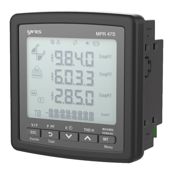
Terminals Front Panel... -
Page 8: Button Functions
1 – Indicates on which quadrant the network is operating. 2 – Indicates that the corresponding screen is one of THD, MIN, MAX or DEMAND screens. 3 – Indicates the total screen. (I.e. ΣTHD) 4 – Indicates the percent values. 5 –... -
Page 9: Terminal Structure
Up Button (12) : It has 2 main functions: While on measuring screen: As seen on the symbols (THD H) above the button, it is used to browse between THDV, THDI and individual harmonic measurement screens. While on menu screens: It is used to browse between menu options and to increase a value during adjustment. -
Page 10: Installation
INSTALLATION Device has 5 different connection configurations. These configurations are explained with diagrams below 3P4W (3 Phase with Neutral) Connection For this configuration, four voltage connections (including neutral line) and four current connections are used. 3P3W (3 Phase without Neutral) Connection For this configuration, three voltage connections and four current connections are used. -
Page 11: Aron Without Neutral Connection
Aron without Neutral Connection For this configuration, three voltage connections and two current connections are used 3P4W BLN (3 Phase Balanced with Neutral) Connection For this configuration, four voltage connections and one current connection is used. The device shows the same current value, which is measured from the first phase, for the unconnected phases. -
Page 12: 3P3W Bln (3 Phase Balanced Without Neutral) Connection
3P3W BLN (3 Phase Balanced without Neutral) Connection For this configuration, three voltage connections and one current connection is used. The device shows the same current value, which is measured from the first phase, for the unconnected phases. -
Page 13: Connection Test
Connection Test After finishing device connections, you can check the connection that you’ve done by using the automatic test function. When you press the BACK button for 3 seconds, it switches to test mode. During this mode, at least 20% of the nominal voltage must be applied to the voltage measuring inputs, at least 10% of the nominal current must be applied to the current measuring inputs and the angle difference between current and voltage inputs must be less than 30 degrees. -
Page 14: Operating Instructions
OPERATING INSTRUCTIONS Measurement Screens Measurement screens, which can be accessed by pressing the related buttons, are explained in this section Current, Voltage and Frequency Screens BUTTON NAME DISPLAYED MEASUREMENT SCREEN ESC (VIF) VOLTAGE (L-N) BUTTON NAME DISPLAYED MEASUREMENT SCREEN ESC (VIF) VOLTAGE (L-L) BUTTON NAME DISPLAYED MEASUREMENT SCREEN... - Page 15 BUTTON NAME DISPLAYED MEASUREMENT SCREEN ESC (VIF) V- UNBALANCE BUTTON NAME DISPLAYED MEASUREMENT SCREEN ESC (VIF) I- UNBALANCE BUTTON NAME DISPLAYED MEASUREMENT SCREEN ESC (VIF) WORK HOUR COUNTER 1 BUTTON NAME DISPLAYED MEASUREMENT SCREEN ESC (VIF) WORK HOUR COUNTER 2...
-
Page 16: Power And Power Factor Screens
Power and Power Factor Screens BUTTON NAME DISPLAYED MEASUREMENT SCREEN BACK (P PF) TOTAL POWER BUTTON NAME DISPLAYED MEASUREMENT SCREEN BACK (P PF) ACTIVE POWER BUTTON NAME DISPLAYED MEASUREMENT SCREEN BACK (P PF) REACTIVE POWER... - Page 17 BUTTON NAME DISPLAYED MEASUREMENT SCREEN BACK (P PF) APPARENT POWER BUTTON NAME DISPLAYED MEASUREMENT SCREEN BACK (P PF) POWER FACTOR BUTTON NAME DISPLAYED MEASUREMENT SCREEN COS φ BACK (P PF)
-
Page 18: Energy And Time Screens
Energy and Time Screens BUTTON NAME DISPLAYED MEASUREMENT SCREEN DOWN Import Active Energy BUTTON NAME DISPLAYED MEASUREMENT SCREEN DOWN Export Active Energy BUTTON NAME DISPLAYED MEASUREMENT SCREEN DOWN Import Reactive Energy... - Page 19 BUTTON NAME DISPLAYED MEASUREMENT SCREEN DOWN Export Reactive Energy BUTTON NAME DISPLAYED MEASUREMENT SCREEN DOWN Apparent Energy BUTTON NAME DISPLAYED MEASUREMENT SCREEN DOWN Active Energy in Total Tariff...
- Page 20 BUTTON NAME DISPLAYED MEASUREMENT SCREEN DOWN Active Energy in Active Tariff BUTTON NAME DISPLAYED MEASUREMENT SCREEN DOWN Energy Values for each Programmed Tariff (T1, T2, T3, T4, T5, T6, T7, T8, TG) BUTTON NAME DISPLAYED MEASUREMENT SCREEN DOWN Time...
-
Page 21: Thd And Harmonics Screens
BUTTON NAME DISPLAYED MEASUREMENT SCREEN DOWN Date THD and Harmonics Screens For models with THD, only current THD and voltage THD screens will be displayed. For models with harmonics, separate harmonics for current and voltage can be displayed also. BUTTON NAME DISPLAYED MEASUREMENT SCREEN THD V BUTTON NAME DISPLAYED MEASUREMENT SCREEN VOLTAGE HARMONICS (H01, H02, ..., H51 in order) (Only for MPR47S model) -
Page 22: Minimum, Maximum And Demand Screens
Current screen is displayed when “V I F” button is pressed. When THD H button is pressed at this point, following screens are displayed. BUTTON NAME DISPLAYED MEASUREMENT SCREEN THD I BUTTON NAME DISPLAYED MEASUREMENT SCREEN CURRENT HARMONICS (H01, H02, ..., H51 in order) (Only for MPR47S model) Minimum, Maximum and Demand Screens To see the minimum and maximum values of current and voltage, first select the relevant screen with “V I F”... - Page 23 BUTTON NAME DISPLAYED MEASUREMENT SCREEN MIN(Phase-Neutral Voltage) BUTTON NAME DISPLAYED MEASUREMENT SCREEN MAX (Phase-Phase Voltage) BUTTON NAME DISPLAYED MEASUREMENT SCREEN MIN (Phase-Phase Voltage)
- Page 24 BUTTON NAME DISPLAYED MEASUREMENT SCREEN MAX I BUTTON NAME DISPLAYED MEASUREMENT SCREEN MIN I To see the minimum, maximum and demand values of power parameters, first select the relevant screen with “P PF” button. Afterwards, you can display the following screens with MAX/MIN DEMAND. BUTTON NAME DISPLAYED MEASUREMENT SCREEN DEMAND P...
- Page 25 BUTTON NAME DISPLAYED MEASUREMENT SCREEN MAX DEMAND P BUTTON NAME DISPLAYED MEASUREMENT SCREEN MAX P BUTTON NAME DISPLAYED MEASUREMENT SCREEN MIN P...
- Page 26 BUTTON NAME DISPLAYED MEASUREMENT SCREEN MAX Q BUTTON NAME DISPLAYED MEASUREMENT SCREEN MIN Q BUTTON NAME DISPLAYED MEASUREMENT SCREEN DEMAND S...
- Page 27 BUTTON NAME DISPLAYED MEASUREMENT SCREEN MAX DEMAND S BUTTON NAME DISPLAYED MEASUREMENT SCREEN MAX S BUTTON NAME DISPLAYED MEASUREMENT SCREEN MIN S...
-
Page 28: Setup Screen
Setup Screen Accessing the Programming Menu: When the SET button of the device is pressed for 3 seconds with PIN feature activated, entry screen is displayed. When the password is entered correctly, programming menu is reached. If PIN feature is not activated, programming menu is reached directly. Password for the device is 1234 as factory default. - Page 29 Voltage Transformer Usage 1. By using UP/DOWN buttons, select Enable or Disable indicating whether you use a voltage transformer on your system. 2. Press the SET button and go to the next step. VT Secondary Value 1. Enter the secondary value of your VT by using SET and UP/DOWN buttons. 2.
- Page 30 CT Secondary Value Selection 1. By using UP/DOWN buttons, select your CT secondary value type as 1A or 5A. 2. After selecting the necessary value, Press the SET button and go to the next step. CT Primary Value 1. Enter the primary value of your CT between 1 and 9999 A by using SET and UP/DOWN buttons. 2.
- Page 31 Nominal Operating Voltage Value 1. Enter the nominal operating voltage value between 25 and 300 V by using SET and UP/DOWN buttons. 2. You can approve a digit value by pressing the SET button. 3. After entering the necessary value, Press the SET button and go to the next step. Time Zone Setting 1.
-
Page 32: Display Settings
Hour Setting 1. Enter the time by using SET and UP/DOWN buttons. 2. You can approve a digit value by pressing the SET button. 3. After entering the correct date, Press the SET button and go to the next step. Display Settings Language settings, display contrast and backlight settings are located under Display Settings section Language Setting... -
Page 33: Time Settings
There are three settings for the backlight of the device: Always ON, Always OFF, Automatic. When “Automatic” option is selected, the backlight turns on after a button is pressed and turns off after no button is pressed for 3 minutes. 1. - Page 34 5. Adjust the hour by using UP/DOWN buttons. 6. Press the SET button to switch to the minute value. Repeat these steps for minutes and seconds parts. 7. When exiting from the menu with the BACK or ESC button, don’t forget to save the changes. Date Setting The date of the device’s RTC module can be set in days, months and years.
-
Page 35: Rs-485 Communication Settings
DST Mode Setting 1. Press the SET button while Clock DST Mode screen is displayed. 2. Daylight Save screen is displayed. 3. Press the SET button and select one of EUROPE, USA, MANUEL and DISABLE options. 4. If you select MANUEL option; you will have to enter month, week, day and hour for the start of DST in that order. -
Page 36: Input Parameter Settings
3. 9600 baud 4. 19200 baud 5. 38400 baud 6. 57600 baud 7. 115200 baud 1. Press the SET button while on RS-485 baud rate screen. 2. Press the SET button to start selecting the baudrate value. 3. Select your communication speed by using UP/DOWN buttons. 4. - Page 37 2. Generator Input: When this option is selected, the device records the energy to the generator register depending on the input state. 3. Pulse Input: When this option is selected, the device can count the pulses that occur on the input. It can display the pulse count on monitoring screens under "Pulse Cntr C-1"...
-
Page 38: Output Parameter Settings
Pulse input menu will be activated when pulse option is selected as the input parameter. 1. Press the SET button while on Pulse Inputs menu. 2. On the displayed selection screen, press the SET button to start the selection. 3. Select a pulse width by using UP/DOWN buttons. 4. -
Page 39: Recording Settings
1. Press the SET button while on Outputs menu. 2. Select the relevant output number and press the SET button to start the selection. 3. Select an output operation type mentioned above by using UP/DOWN buttons. 4. When exiting from the menu with the BACK or ESC button, don’t forget to save the changes. Recording Settings The following parameters can be recorded to the internal memory of the device in adjustable time intervals. -
Page 40: Voltage Settings
Voltage Settings 1. Press the SET button while Log Setup-Voltages is displayed. 2. Current option is displayed. Press the SET button again. 3. Select Active or Passive with UP/DOWN buttons. Press the SET button. 4. If you select Active option, recording time interval selection will be active. 5. - Page 41 5. Select you recording time interval in seconds with UP/DOWN buttons. 6. Finish the selection by pressing the SET button. 7. When exiting from the menu with the BACK or ESC button, don’t forget to save the changes. THD Settings 1.
-
Page 42: Pulse Input Settings
A free software is available to read the log values that are stored on the device. It can be downloaded from the following link: http://www.entes.com.tr/dosyalar/Applications/Mpr3x4xLogReader/publish.htm Accessing the records according to index For this method, the user writes the record index number to the index register at the bottom of the tables at register addresses 23000, 24000, 25000 etc., the details of the entered register will be... -
Page 43: Pulse Output Settings
Selecting Pulse-1 Ratio 1. Press UP button while PULSE IN-1 Enable is displayed. 2. This value indicates for how many incoming pulses the device will increase the pulse counter. Select this value as displayed above. 3. Exit from the menu when selection is complete. 4. - Page 44 When Pulse Output is selected, the device can create pulses for import or export active energy according to the increments listed below. Import or export energy can be selected as the source. 1. 1 Wh 2. 10 Wh 3. 100 Wh 4.
-
Page 45: Operating Hours Settings
Pulse Output Duration Setting The duration during the pulse stays at logic-1 level is entered here. 1. Press SET button while PULS DURATION is displayed. 2. Enter the duration in seconds with 0.01 second increments with UP/DOWN buttons. 3. Exit from the menu when selection is complete. 4. -
Page 46: Alarm Settings
1. Press SET button while HOUR COUN PARA is displayed. 2. Select the parameter with UP/DOWN buttons. 3. Press the SET button. Afterwards, the limit value is selected. When the parameter exceeds this limit value, hour counter will start. 1. Press SET button while HOUR COUN LEVL is displayed. 2. - Page 47 4. When exiting from the menu with the BACK or ESC button, don’t forget to save the changes. Alarm Parameter Selection Alarm parameter is selected by following these steps: 1. Press the SET button while Alarm Setup is displayed. 2. Find Alarm Parameter by pressing UP/DOWN buttons. 3.
- Page 48 Alarm Operation Type Selection 1. While AL-1 OPE RAND is displayed, press the SET button to select the alarm operation type. 2. Select one of the following options by using UP/DOWN buttons: a. In window b. Out window c. Lower than d.
- Page 49 Low Alarm Limit Setting A low limit for the alarm is entered in this menu. 1. While Alarm Enable is selected, find Alarm Low menu with UP/DOWN buttons. 2. Press the SET button. Enter the low alarm limit with UP/DOWN buttons. 3.
-
Page 50: Tariff Settings
4. Find oFF dELY menu with UP/DOWN buttons to enter an Alarm Off Delay value. 5. Press the SET button. Enter the alarm OFF delay value in seconds for the alarm UP/DOWN buttons. Go to the next digit with SET button. When the alarm conditions are cleared on the system, the alarm will be deactivated after the entered time passes 6. -
Page 51: Reset Settings
Reset Settings Users can reset the minimum, maximum, demand and log records that the device has stored Resetting Maximum Values 1. Select Maximum under Reset menu and press the SET button. 2. Press the SET button while "Reset High" is displayed and select YES option with UP/DOWN buttons. 3. - Page 52 4. When exiting from the menu with the BACK or ESC button, don’t forget to save the changes. Resetting Maximum Demand Values 1. Select Max Demand under Reset menu and press the SET button. 2. Press the SET button while "Reset de" is displayed and select YES option with UP/DOWN buttons. 3.
- Page 53 Resetting Tariff Energy Values 1. Select Tariff under Reset menu and press the SET button. 2. Press the SET button while "Reset Tariff" is displayed and select YES option with UP/DOWN buttons. 3. Press the SET button. 4. When exiting from the menu with the BACK or ESC button, don’t forget to save the changes. Resetting Pulse Counter Values 1.
-
Page 54: System Settings
Resetting Log Values 1. Select Logs under Reset menu and press the SET button. 2. Press the SET button while "Reset Logs" is displayed and select YES option with UP/DOWN buttons. 3. Press the SET button. 4. When exiting from the menu with the BACK or ESC button, don’t forget to save the changes. System Settings Pin Code Activation Preventing access to settings menu with a password can be accomplished from this menu. - Page 55 1. Find "Pin Chng" option under System Menu. Press the SET button. 2. While "Pin CHAnGE" is displayed, press the SET button. 3. Enter the old pin digit by digit with UP/DOWN buttons. 4. If you enter the old pin incorrectly, "ERROR" will be displayed. 5.
- Page 56 Displaying Software and Hardware Version The device’s hardware and software version can be displayed under this menu: 1. Press the SET button while "Soft VER" is displayed under System menu. 2. Software version of the device will be displayed on the bottom of the screen. 3.
-
Page 57: Analog Output Settings
Analog Output Settings When an analog output module is connected to the device, the purpose of the output is selected from this menu. Analog Output-1 Type Settings 1. Press the SET button while Analog O-1 Type is displayed. 2. Select one of 0-5V, 0-10V, -5 ~ 5V and -10 ~ 10V options with UP/DOWN buttons. 3. - Page 58 Analog Output-1 High Value Settings 1. Press the SET button while Analog O-1 High is displayed. 2. Enter your high value with UP/DOWN buttons. 3. After entering your value, press the SET button. 4. When exiting from the menu with the BACK or ESC button, don’t forget to save the changes. Analog Output-1 Low Value Settings 1.
- Page 59 Analog Output-2 Type Settings 1. Press the SET button while Analog O-2 Type is displayed. 2. Select one of 0-5V, 0-10V, -5 ~ 5V and -10 ~ 10V options with UP/DOWN buttons. 3. After completing your selection, press the SET button. 4.
-
Page 60: Reporting Screen
Analog Output-2 Low Value Settings 1. Press the SET button while Analog O-2 Low is displayed. 2. Enter your low value with UP/DOWN buttons. 3. After entering your value, press the SET button. 4. When exiting from the menu with the BACK or ESC button, don’t forget to save the changes. Reporting Screen When the ESC button of the device is pressed for 3 seconds, recorded event details can be browsed. - Page 61 3. End date, 4. End time, 5. Duration, 6. Parameter, 7. Source of the event (if the event type is alarm), 8. Value that caused the event (if the event type is alarm). If no button is pressed for 60 seconds, the device returns to measuring screen.
-
Page 62: Technical Features And Appendix
TECHNICAL FEATURES AND APPENDIX Technical Features 45 – 265 VAC/DC Operating Voltage (Un) Operating Frequency (f) 45-65 Hz Supply Input Burden <5 VA Supply Input Burden <1 VA 10 – 300 VAC (L-N) Measuring Voltage Input (Vin) 10 – 690 VAC (L-L) 0.05 –... - Page 63 Cable Thickness For Current Connection Max. 2.5 mm Cable Thickness For RS-485 Connection CAT 5 Cable Weight 0.335 kg/pcs...
-
Page 64: Measurement Menu Map 1
Measurement Menu Map 1... -
Page 65: Measurement Menu Map 2
Measurement Menu Map 2...
Need help?
Do you have a question about the MPR-45 and is the answer not in the manual?
Questions and answers