Table of Contents
Advertisement
MPR-3 SERIES NETWORK ANALYSER USER
MANUAL
INDEX
SAFETY AND WARNINGS ........................................................................................................ 3
Warning .................................................................................................................................. 3
Safety ..................................................................................................................................... 3
Warranty................................................................................................................................. 3
OPERATING CONDITIONS....................................................................................................... 4
INTRODUCTION ....................................................................................................................... 5
General Features ................................................................................................................... 5
Applications ........................................................................................................................... 6
MPR-3 Series Products .......................................................................................................... 6
Overview ................................................................................................................................ 7
Terminals ............................................................................................................................... 7
Front Panel ......................................................................................................................... 8
Button Functions ................................................................................................................. 9
Terminal Structure ............................................................................................................ 10
INSTALLATION ....................................................................................................................... 10
3P4W (3 Phase with Neutral) Connection............................................................................. 10
3P3W (3 Phase without Neutral) Connection........................................................................ 11
Aron without Neutral Connection .......................................................................................... 11
3P4W BLN (3 Phase Balanced with Neutral) Connection ..................................................... 12
3P3W BLN (3 Phase Balanced without Neutral) Connection ................................................ 12
Connection Test ................................................................................................................... 13
Line Termination Resistor..................................................................................................... 13
OPERATING INSTRUCTIONS ................................................................................................ 14
Measurement Screens ......................................................................................................... 14
Current, Voltage and Frequency Screens ......................................................................... 14
Power and Power Factor Screens..................................................................................... 15
Energy and Harmonics Screens........................................................................................ 17
Minimum, Maximum and Demand Screens ....................................................................... 19
1
Advertisement
Table of Contents

Subscribe to Our Youtube Channel
Related Manuals for Entes MPR-32


Summary of Contents for Entes MPR-32
-
Page 1: Table Of Contents
MPR-3 SERIES NETWORK ANALYSER USER MANUAL INDEX SAFETY AND WARNINGS ......................3 Warning ..........................3 Safety ............................. 3 Warranty..........................3 OPERATING CONDITIONS....................... 4 INTRODUCTION ........................5 General Features ........................5 Applications ........................... 6 MPR-3 Series Products ......................6 Overview ..........................7 Terminals .......................... - Page 2 Setup Screen........................25 Device Installation Settings ....................25 Display Settings ....................... 30 Time Settings ........................31 RS-485 Communication Settings ..................33 Input Parameter Settings ....................34 Output Parameter Settings....................35 Pulse Output Settings ....................... 36 Operating Hours Settings ....................38 Alarm Settings .........................
-
Page 3: Safety And Warnings
SAFETY AND WARNINGS Warning Failure to follow the instructions below may result in serious injury or death. Cut all power before connecting the device. Do not connect the current measurement inputs directly to the current source. Always connect the current source using a current transformer. -
Page 4: Operating Conditions
OPERATING CONDITIONS Operating Conditions Range 95 - 270 VAC/VDC(Tolerance up to ±10%) Supply Voltage (Tolerances up to ± 10%) Supply Frequency 50 ~ 60 Hz. Maximum Measuring Current 5,5 A Maximum Measuring Voltage 480 VAC (VLL) -10 ~ +55 ºC Operating Temperature -20 ~ +70 ºC Storing Temperature... -
Page 5: Introduction
INTRODUCTION General Features Wide supply range (95 – 270 Vrms) Custom FSTN display with backlight 3 voltage measuring inputs 3 current measuring inputs 4 language options 1MB internal memory Real time clock Alarm Hour counters (Operating hour and total hour) Communication via RS-485 Measured parameters: ... -
Page 6: Applications
Capable of recording 256 events User password Changing primary and secondary values of current and voltage transformers Making measurements on 5 different connection type systems: 3 Phase 4 W ires, 3 Phase 3 Wires, 3 Phase Aron, 3 Phase 4 W ires Balanced, 3 Phase 3 Wires Balanced Contrast setting Backlight setting Demand and integration time setting... -
Page 7: Overview
Overview Terminals Voltage Inputs V1 -> 1st Phase Voltage Input V2 -> 2nd Phase Voltage Input V3 -> 3rd Phase Voltage Input N -> Neutral Input Supply Input Digital Input / Output (On models with two inputs, they are used as IN1 and IN2 inputs) Out ->... -
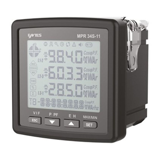
Page 8: Front Panel
Back Panel of the model with two inputs Front Panel 1 – Indicates on which quadrant the network is operating. 2 – Indicates that the displayed value is negative. 3 – Indicates that the measurement is inductive or capacitive 4 – Indicates that the digital output is active. 5 –... -
Page 9: Button Functions
7 – Indicates that the RTC is reset and stays on until RTC is adjusted. 8 – Indicates that there is a phase sequence error. 9 – Indicates that there is a warning 10 – Indicates that the alarm output is active. 11 –... -
Page 10: Terminal Structure
Terminal Structure 1) 185 - 300 VAC/VDC Supply Input 3 terminal connections (2 pins) 2) Current measuring input terminal block (6 pins): L1 L2 L3 ve N 3) Voltage measuring input terminal block (4 pins): L1 L2 L3 and N 4) RS-485 terminal block (2 pins) 5) Digital Input/Output terminal (4 pins) INSTALLATION... -
Page 11: 3P3W (3 Phase Without Neutral) Connection
3P3W (3 Phase without Neutral) Connection For this configuration, three voltage connections and three current connections are used. Aron without Neutral Connection For this configuration, three voltage connections and two current connections are used. -
Page 12: 3P4W Bln (3 Phase Balanced With Neutral) Connection
3P4W BLN (3 Phase Balanced with Neutral) Connection For this configuration, four voltage connections and one current connection is used. The device shows the same current value, which is measured from the first phase, for the unconnected phases. 3P3W BLN (3 Phase Balanced without Neutral) Connection For this configuration, three voltage connections and one current connection is used. -
Page 13: Connection Test
Connection Test After finishing device connections, you can check the connection that you’ve done by using the automatic test function. When you press the BACK button for 3 seconds, it switches to test mode. During this mode, at least 20% of the nominal voltage must be applied to the voltage measuring inputs, at least 10% of the nominal current must be applied to the current measuring inputs and the angle difference between current and voltage inputs must be less than 30 degrees. -
Page 14: Operating Instructions
OPERATING INSTRUCTIONS Measurement Screens Measurement screens, which can be accessed by pressing the related buttons, are explained in this section. Current, Voltage and Frequency Screens BUTTON NAME DISPLAYED MEASUREMENT SCREEN BACK (VIF) VOLTAGE (L-N) BUTTON NAME DISPLAYED MEASUREMENT SCREEN BACK (VIF) VOLTAGE (L-L) -
Page 15: Power And Power Factor Screens
BUTTON NAME DISPLAYED MEASUREMENT SCREEN BACK (VIF) CURRENT BUTTON NAME DISPLAYED MEASUREMENT SCREEN BACK (VIF) FIRST HOUR COUNTER BUTTON NAME DISPLAYED MEASUREMENT SCREEN BACK (VIF) SECOND HOUR COUNTER Power and Power Factor Screens BUTTON NAME DISPLAYED MEASUREMENT SCREEN DOWN (P PF) TOTAL POWER... - Page 16 BUTTON NAME DISPLAYED MEASUREMENT SCREEN DOWN (P PF) ACTIVE POW ER BUTTON NAME DISPLAYED MEASUREMENT SCREEN DOWN (P PF) REACTIVE POW ER BUTTON NAME DISPLAYED MEASUREMENT SCREEN DOWN (P PF) APPARENT POW ER BUTTON NAME DISPLAYED MEASUREMENT SCREEN DOWN (P PF) POW ER FACTOR...
-
Page 17: Energy And Harmonics Screens
BUTTON NAME DISPLAYED MEASUREMENT SCREEN COS φ DOWN (P PF) Energy and Harmonics Screens BUTTON NAME DISPLAYED MEASUREMENT SCREEN THD L-N BUTTON NAME DISPLAYED MEASUREMENT SCREEN THD L-L BUTTON NAME DISPLAYED MEASUREMENT SCREEN THD IN... - Page 18 BUTTON NAME DISPLAYED MEASUREMENT SCREEN Import Active Energy BUTTON NAME DISPLAYED MEASUREMENT SCREEN Export Active Energy BUTTON NAME DISPLAYED MEASUREMENT SCREEN Import Reactive Energy BUTTON NAME DISPLAYED MEASUREMENT SCREEN Export Reactive Energy...
-
Page 19: Minimum, Maximum And Demand Screens
BUTTON NAME DISPLAYED MEASUREMENT SCREEN Apparent Energy BUTTON NAME DISPLAYED MEASUREMENT SCREEN Time BUTTON NAME DISPLAYED MEASUREMENT SCREEN Date Minimum, Maximum and Demand Screens To see the minimum and maximum values of current and voltage, first select the relevant screen with “V I F”... - Page 20 BUTTON NAME DISPLAYED MEASUREMENT SCREEN SET (MAX/MIN) MAX(Phase-Neutral Voltage) BUTTON NAME DISPLAYED MEASUREMENT SCREEN SET (MAX/MIN) MIN(Phase-Neutral Voltage) BUTTON NAME DISPLAYED MEASUREMENT SCREEN SET (MAX/MIN) MAX (Phase-Phase Voltage) BUTTON NAME DISPLAYED MEASUREMENT SCREEN SET (MAX/MIN) MIN (Phase-Phase Voltage)
- Page 21 BUTTON NAME DISPLAYED MEASUREMENT SCREEN SET (MAX/MIN) DEMAND I BUTTON NAME DISPLAYED MEASUREMENT SCREEN SET (MAX/MIN) MAX DEMAND I BUTTON NAME DISPLAYED MEASUREMENT SCREEN SET (MAX/MIN) MAX I...
- Page 22 BUTTON NAME DISPLAYED MEASUREMENT SCREEN SET (MAX/MIN) MIN I To see the minimum, maximum and demand values of power parameters, first select the relevant screen with “P PF” button. Afterwards, you can display the following screens with MAX/MIN DEMAND. BUTTON NAME DISPLAYED MEASUREMENT SCREEN SET (MAX/MIN) DEMAND P BUTTON NAME DISPLAYED MEASUREMENT SCREEN SET (MAX/MIN) MAX DEMAND P...
- Page 23 BUTTON NAME DISPLAYED MEASUREMENT SCREEN SET (MAX/MIN) MAX P BUTTON NAME DISPLAYED MEASUREMENT SCREEN SET (MAX/MIN) MIN P BUTTON NAME DISPLAYED MEASUREMENT SCREEN SET (MAX/MIN) MAX Q...
- Page 24 BUTTON NAME DISPLAYED MEASUREMENT SCREEN SET (MAX/MIN) MIN Q BUTTON NAME DISPLAYED MEASUREMENT SCREEN SET (MAX/MIN) DEMAND S BUTTON NAME DISPLAYED MEASUREMENT SCREEN SET (MAX/MIN) MAX DEMAND S...
-
Page 25: Setup Screen
BUTTON NAME DISPLAYED MEASUREMENT SCREEN SET (MAX/MIN) MAX S BUTTON NAME DISPLAYED MEASUREMENT SCREEN SET (MAX/MIN) MIN S Setup Screen Accessing the Programming Menu When the SET button of the device is pressed for 3 seconds with PIN feature activated, entry screen is displayed. - Page 26 Language Setting Messages on the device screen can be viewed in four languages: 1. Turkish 2. English 3. German 4. French After selecting your language with UP/DOWN buttons, Press the SET button and go to the next step. Connection Type Setting 1.
- Page 27 VT Secondary Value 1. Enter the secondary value of your VT by using SET and UP/DOWN buttons. 2. You can approve a digit value by pressing the SET button. 3. After entering the necessary value, Press the SET button and go to the next step. VT Primary Value 1.
- Page 28 CT Primary Value 1. Enter the primary value of your CT between 1 and 9999 A by using SET and UP/DOWN buttons. 2. You can approve a digit value by pressing the SET button. 3. After entering the necessary value, Press the SET button and go to the next step. Nominal Frequency Value Selection 1.
- Page 29 Time Zone Setting 1. By using UP/DOW N buttons, you can select the time zone information about the device location between -12:00 and +12:00 in 30 minute intervals. After selecting the necessary value, Press the SET button and go to the next step Date Setting 1.
-
Page 30: Display Settings
Display Settings Language settings, display contrast and backlight settings are located under Display Settings section. Language Setting Messages on the device screen can be viewed in four languages: 1. Turkish 2. English 3. German 4. French 1. Select Language option under Settings/Display and press SET button. 2. -
Page 31: Time Settings
Display Contrast Setting Display contrast of the device can be selected between 0 and 15. The factory default value is 3. 1. Select Contrast option under Settings/Display and press SET button. 2. Current contrast option will start blinking. Select one of the options and press SET button. 3. - Page 32 The date of the device’s RTC module can be set in hours, minutes and seconds. To set the date, follow these steps: 1. Press the SET button on the Date Set screen. 2. Press the SET button. Adjust the day with UP/DOWN buttons. 3.
-
Page 33: Rs-485 Communication Settings
RS-485 Communication Settings RS-485 Address Setting 1. Select Address option under Settings/RS-485 and press SET button. 2. Current address option will start blinking. You can browse between digits with SET and BACK buttons. Select an address between 1 and 247 and press SET button. 3. -
Page 34: Input Parameter Settings
RS-485 Parity Setting Communication parity of the device can be set as Odd, Even or None. Factory default setting for parity is NONE. 1. Press the SET button while on RS-485 parity screen. 2. Press the SET button to start selecting the parity option. 3. -
Page 35: Output Parameter Settings
Output Parameter Settings Digital output of the device can be used for one of the following applications: 1. Output as Pulse: When this option is selected, the device creates output pulses depending on selected value of active or reactive energy consumption. 2. -
Page 36: Pulse Output Settings
Pulse Output Settings Pulse Output According to Active Energy 1. Press UP button while OUTPUT 1 PULSE is displayed. 2. Select the energy value for which the device will create pulse signals. 3. Exit from the menu when selection is complete. 4. - Page 37 Output is selected, the device can create pulses for import or export reactive energy according to the increments listed below. Reactive energy values from Q1, Q2, Q3 and Q4 quadrants can be used as source. 1 VArh 10 VArh 100 VArh 1 kVArh 10 kVArh 100 kVArh.
-
Page 38: Operating Hours Settings
Operating Hours Settings The device can count the time when a selected parameter exceeds or falls below an adjusted limit value. This feature is explained in this section. Parameter is selected under Hour Counter menu. If you select VLN for example, display changes as following. -
Page 39: Alarm Settings
Alarm Settings Different parameters can be assigned to the 4 alarms that the device has. Following operations are described for a single alarm but they are the same for the other 3 alarms. Activating Alarm Alarm is activated by following these steps: 1. - Page 40 o. Cos phi p. Total Cos phi q. Frequency THDV THDU THDI u. Hour Counter v. Digital Input w. Tariffs x. Phase-Neutral Voltage Phase-Phase Voltage 5. Press the SET button after completing your selection. You can start selecting the Alarm Operation Type by pressing the UP button.
- Page 41 5. When exiting from the menu with the BACK button, don’t forget to save the changes. Low Alarm Limit Setting A low limit for the alarm is entered in this menu. 1. While Alarm Enable is selected, find Alarm Low menu with UP/DOWN buttons. 2.
-
Page 42: Reset Settings
3. Press the SET button after completing your entering. 4. Find oFF dELY menu with UP/DOWN buttons to enter an Alarm Off Delay value. 5. Press the SET button. Enter the alarm OFF delay value in seconds for the alarm UP/DOWN buttons. - Page 43 Resetting Demand Values 1. Select Demand under Reset menu and press the SET button. 2. Press the SET button while "Reset High d" is displayed and select YES option with UP/DOWN buttons. 3. Press the SET button. 4. When exiting from the menu with the BACK button, don’t forget to save the changes. Resetting Maximum Demand Values 1.
-
Page 44: System Settings
Resetting Generator Energy Values 1. Select Gen Energy under Reset menu and press the SET button. 2. Press the SET button while "Reset GenE" is displayed and select YES option with UP/DOWN buttons. 3. Press the SET button. 4. When exiting from the menu with the BACK button, don’t forget to save the changes. Resetting Hour Counter Value 1. - Page 45 2. When you press the SET button while "Pin Acivate" is displayed, you will have to enter the 4 digit factory default pin (mentioned below). 3. Select the default pin digits with UP/DOWN buttons and confirm the digit with SET button. 4.
- Page 46 Resetting to Factory Settings 1. To reset the device to factory settings, press the SET button while "FACT RST" is displayed. 2. While "FACtorY rSET" is displayed, pin code must be entered when the SET button is pressed. 3. Enter your pin code with UP/DOW N buttons. Press the SET button. 4.
-
Page 47: Reporting Screen
Reporting Screen When the BACK button of the device is pressed for 3 seconds, recorded event details can be browsed. The device can record 255 events. Recorded event types: First commission, short interruption (<3 s), long interruption, alarm, settings change, time change and value reset. Different records can be viewed with UP/DOWN buttons. -
Page 48: Reading The Records Via Modbus
A free software is available to read the log values that are stored on the device. It can be downloaded from the following link: http://www.entes.com.tr/dosyalar/Applications/Mpr3x4xLogReader/publish.htm Accessing the records according to index For this method, the user writes the record index number to the index register at the bottom of the tables at register addresses 23000, 24000, 25000 etc., the details of the entered register will be... -
Page 49: Technical Features And Appendix
TECHNICAL FEATURES AND APPENDIX Technical Features 95 - 270 VAC/VDC (Tolerance up to ±10%) Operating Voltage (Un) Operating Frequency (f) 50-60 Hz Supply Input Burden <4 VA Voltage Measuring Input Burden <0.5 VA Current Measuring Input Burden <1 VA 10 – 300 VAC (L-N) Measuring Voltage Input (Vin) 10 –... -
Page 50: Applicable Standards
Applicable Standards IEC 61557-12 CONFORMITY IEC 61557-12 Edition 2 PMD SPECIFICATIONS Examples of possible Other additional Type of Specification specification values specifications Supply quality evaluation function (option) PMD Classification Setpoint Humidity + Altitude Operationg performance class for active power or active energy (if function availible) Operating performance class, Symbol for... - Page 51 Standard Year Title Electrical safety in low voltage distribution systems up to 1000 V a.c. and 1500 V d.c. - Equipment for testing, measuring or monitoring of protective measures - Part 12: IEC 61557-12 2008 Performance measuring and monitoring devices Electrical equipment for measurement, control and laboratory use - EMC IEC 61326-1 2005...
Need help?
Do you have a question about the MPR-32 and is the answer not in the manual?
Questions and answers