Advertisement
NETWORK ANALYSER
MPR-53/53S
TECHNICAL DATA
Operating Voltage (Un)
: Please look behind the device.
Operating frequency (f)
: 45-65 Hz
Auxiliary supply Power Consumption : < 4 VA
Measuring Input Power Consumption: < 1VA
V In
: 10-300 V AC 45-65 Hz. (L-N)
: 10-500 V AC 45-65 Hz. (L-L)
I In
: 0.05 - 5.5 A~
2-120 A~ (for CT-25)
Measuring Range
: 10V...200 kV AC
: 0...215 M (W,VAr,VA)
: 99999999999.9 kWh, kVArh
Class
: 1% ± 1 digit [(10%-110%) xFull Scale]
Voltage Transformer Ratio (Vtr)
: 0,1 ... 4000,0
Current Transformer Ratio (Ctr)
: 1 ... 2000
Max. Ctr x Vtr
: 40.000
Demand Time
: 1-60 min. (programmable)
Serial Interface (for MPR-53S)
: MODBUS RTU (RS 485)
Optically Isolated, programmable
Baud Rate (for MPR-53S)
: 2400-38400 bps
Address (for MPR-53S)
: 1-247
Parity (for MPR-53S)
: No, Odd, Even, 8 Data bits, 2 Stop Bits
Pulse Output
: NPN Transistor
Switch Period
: Min. 100 msec pulse perriod
80 msec pulse width
Operation Current
: Max. 50 mA
Operation Voltage
: 5.....24 V DC, max. 30 VDC
Input
: 12...48 V AC / DC
Ambient Temperature
: -5°C; +50°C
Display
: Red LED Display
Dimensions
: PR-19, PK-26
Equipment Protection Class
: Double Insulation-Class II (
Box Protection Class
: IP 40 (front panel)
Box Material
: Non-flammable
Installation
: Panel Mounted (PR-19)
Rail Mounted (PK-26)
2
Wire Thickness (for terminal block)
: 2.5 mm
Weight
: 0.45 kg (PR-19, PK-26)
Installation Category
: Class III
Factory Settings
Trafo :
Eng Cnt :
Ctr (Current Transformer Ratio) : 0001
E-1 (Energy Counter 1) : on
trn (Turn number for CT-25 device): 01
E-2 (Energy Counter 2) : on
Utr (Voltage Transformer Ratio) : 0001.0
CAL (Calculation Method) : 1
PULSE :
rAt (Ratio) : 1k
Pin : 0000 (Not Activated)
o-1 (Output 1) : A-I
o-2 (Output 2) : r-L
RS-485 :
Adr (Address) : 1
dEtý (Delay Time) : 15
Bau (Baud Rate) : 9600
PAr (Parity) : no
PRECAUTIONS FOR INSTALLATION AND SAFE USE
The current terminal connections must be implemented with using CT-25.
Failure to follow those instructions will result in death or serious injury.
- Disconnect all power before working on equipment..
- When the device is connected to the network, do not remove the front panel.
- Do not try to clean the device with solvent or the like.Only clean with dry cloth.
- Verify correct terminal connections when wiring.
- Electrical equipment should be serviced only by your component seller.
- No responsibility is assured by manufacturer or any of its subsidiaries for any consequences arising out of the use of this material.
- Only for rack panel mounting.
)
A3918/Rev.3
8
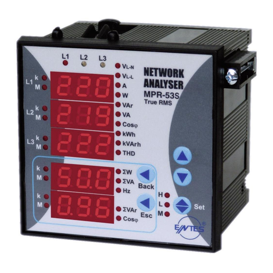
NETWORK ANALYSER
MPR-53/53S
General
MPR-53/53S is developed for measuring all the electrical parameters on the
network. Measured parameters are shown in 5 separate displays.This allows
to monitor more than 50 parameters at the same time. MPR-53S has also
MODBUS serial interface feature.
UP button
DOWN button
Max. LED
SET
Minimum LED
Demand LED
Phase
SW, SVA and
SVAr and
Back
ESC
Displays
Hz Display
Cosj Display
button
button
Phase Displays
SW, SVA and Hz
SVAr ve Cosj
Back
ESC
Display
Display
Using of MPR-53/53S:
Parameters are shown in L1, L2, L3 displays (V
; V
; A; I
; W; VAr; VA; Cosj;
LN
LL
N
kWh, kVarh, THD) by using up-down buttons. Total Active (SW), Total Apparent
Power (SVA) and Frequency (Hz) are selected by back button.
Total Reactive Power (SVAr) and Cosj are selected by Esc button.
Digital Inputs
MPR-53/53S has 2 digital inputs which are used to monitor the status of
electrical contacts. Digital input has 2 functions :
- Enabling remote control of the data received through the digital input terminal
(battery, thermostat, circuit breaker, pumps status)
- Controlling energy counters and determining which energy counter will be
active.
Energy Pulse Outputs
MPR-53/53S has 2 Energy Pulse Outputs. These outputs give the pulses only
for E-1 (Energy Counter).
Pul1 and Pul2: In “o-1 (Pulse1)”, “o-2 (Pulse2)” menus which are in the pulse
menu, device give pulse according to selected energy parameters as [Active
energy (ACt, A-I, A-E), Reactive energy (rEA, r-L, r-C)].
Please refer to the pulse menu for the coefficients of energies.
Monitoring of Min.,Max. and Max. Demand Values:
Min. and max. values are defined for V
, V
, A, W, VAr, VA, SW, SVAr, SVA;
LN
LL
demand values are defined for A, W, VAr, VA, SW, SVA, SVAr.
If measured instant value is smaller than min. value which was stored before,
it is stored as new min. value. If measured instant value is greater than max.
value which was stored before, it is stored as new max. value.
Demand value is the average value of the measured values in demand time
(15 minute).
If one of defined parameters is displayed (ie. “A”) when deman button is
pressed min., max or max. demand values are displayed. When an undefined
parameter is displayed (ie. “Cosj”) if demand button is pressed, instant value
is continued to display.
Monitoring THD Values
When “V
” and “THD” leds light on, voltage THD is monitored and also if “A”
LN
and “THD” leds light on, current THD is monitored.
Monitoring Neutral Current
Neutral current can be monitored by scrolling after 3-phases current values
has displayed.
H-L-M LEDs
H-L-M LEDs are dedicated to displaying the min., max. and max. demand
values according to selected parameters.
H: Maximum Value, L: Minimum Value, M: Max. Demand Value
Calculation Methods for Active / Reactive Power Values
If the led on the most left side blinks it represents that active power’s / reactive
power’s direction is negative.
There are two methods for calculating total active and total reactive powers:
1) Active / Reactive power can be calculated by summing import and export
values and displaying as a single value.
2) Active / Reactive power can be calculated according to direction as
import / export.
Note :
1) The dot at the most right digit of the fourth display (During SW is
displayed) represents that displayed value is export active power value.
Vice versa, displayed value is import active power value.
2) The dot at the most right digit of the fourth display (During SVAr is
displayed) represents that displayed value is capacitive reactive power
value. Vice versa, displayed value is inductive reactive power value.
3) The displayed parameter will not change if power is off after 30 seconds
of stand-by (ie. A).
Measured Parameters:
V
(Phase Voltage )
Cosj
LN
V
(Phase to Phase Voltage)
AI ( kWh) (Import Active Energy I)
LL
A (Phase Current, Neutral Current)
AE (kWh) (Export Active Energy)
W (Active Power)
rI (kVArh) (Import Reactive Energy) SVAr (Total Reactive Power)
VAr (Reactive Power)
rE(kVArh) (Export Reactive Energy) SVA (Total Apparent Power)
VA (Apparent Power)
FUNCTIONS OF BUTTONS
In the monitoring mode, it is used to switch between
(V
, V
, A, W, VAr, VA, Cosj, kWh, kVarh, THD) parameters.
LN
LL
At the programming mode, it provides to increase value of desired
parameter and pass to the next menu.
In the monitoring mode, it is used to pass between
(V
, V
, A, W, VAr, VA, Cosj, kWh, kVarh, THD) parameters.
LN
LL
At the programming mode, it provides to decrease value of desired
UP
parameter and pass to the prevides menu.
(SET) In the monitoring mode, it is used to switch between min.,
DOWN
max., demand and instant values. When it is pressed for 3 seconds,
Max. LED
programming mode it is entered.
SET
In the programming mode, it is used for saving parameters and
moving to the sub menu.
Minimum LED
Demand LED
(Back) In the monitoring mode, it is used to switch between SW, SVA
and Hz parameters. It used to switch to the previous digit in submenu.
(ESC) In the monitoring mode, it provides to switch between SVAr
and Cosj values. In the programming mode, it is used to enter to
the upper menu or it is used to quit from the programming mode
without saving values.
If user password is activated and set button is pressed for 3
seconds, a pin code is required in order to enter to the menu.
Current Transformer Ratio Setup
In this menu, current transformer ratio is set between 1 - 2000.
Note: If the current transformer is not used between the system
and MPR-53/53S, current transformer ratio is entered as ‘1’.
Example: If a current transformer which has a ratio of 250/5A is
used between the system and MPR-53/53S; Current transformer
ratio is entered as “50” (250/5).
Press SET button for 3 seconds (trA Fo menu is displayed)
Press SET button; trA Fo Ctr menu is displayed (In CT-25 adapted
devices, trA Fo trn is displayed instead.)
(Not: trA Fo Utr menu can be displayed by scrolling the UP/DOWN
buttons.)
Press SET button. Blinking the first digit of displayed value appears.
(trA Fo Utr menu can be programmed similarly.)
Enter the blinking digit value by scrolling UP/DOWN buttons.
Switch to the other digits by using SET button, use BACK button
to go to previous digit. After you entered the last digit press SET
button, “trA Fo Ctr / trA Fo trn / trA Fo Utr” is displayed. “on”
can be selected by scrolling UP/DOWN buttons. (Data is entered
but is not activated yet. For activating the new data please follow
the below steps).
Press ESC button one by one until “SAU E SEt yES” is displayed.
Press SET button. When “SAU E SEt yES” is displayed, if you
press ESC button or choose “no” option instead of “yES” option
by using UP-DOWN buttons, new data will be cancelled and
previous value will be activated.
1
THD (Total Harmonic Distortion)
Hz. (Frequency)
SW (Total Active Power)
Advertisement
Table of Contents

Related Manuals for Entes MPR-53S


Summary of Contents for Entes MPR-53S
- Page 1 Operating frequency (f) : 45-65 Hz to monitor more than 50 parameters at the same time. MPR-53S has also There are two methods for calculating total active and total reactive powers: MODBUS serial interface feature. Auxiliary supply Power Consumption : < 4 VA 1) Active / Reactive power can be calculated by summing import and export values and displaying as a single value.
- Page 2 “rES Et dE / rES Et HL / rES Et E-1 / rES Et E-2” is displayed. *Available only for MPR-53S Press SET button. (Most right digit of 5th display blinks) By using UP-DOWN buttons, if you want to delete the min., max., max.
-
Page 3: Pulse Menu
Press SET button (”Pýn ACt IUA tE” Aron wiring configuration menu is displayed.) By using UP-DOWN buttons, select *Available only for MPR-53S “Eng Cnt E-1” / “Eng Cnt E-2”. Press SET button (First digit blinks) Press SET button. (on blinks) -
Page 4: Modbus Rtu Protocol
Available Modbus Function: ERROR CODES (Available only for MPR-53S) Slave device (MPR-53S) sends error message when receive any missing query. READ HOLD REGISTERS Error codes are given below. 01 Invalid Function: If any message except given above is used, then 01 error PRESET SINGLE REGISTER messages will be sent. -
Page 5: Modbus Register Map
5: 100 kW / Pulse 0 : On (EC -Energy counter- will count on all conditions) PARITY 0-2 : *Available only for MPR-53S 5: Reactive Export 6: 1 MW / Pulse 1: EC will count when Digital Input1 is 1 (1=active)
Need help?
Do you have a question about the MPR-53S and is the answer not in the manual?
Questions and answers