Subscribe to Our Youtube Channel
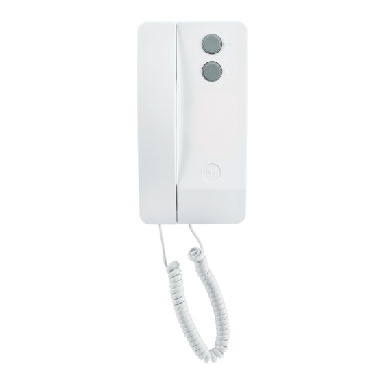
Summary of Contents for CAME BPT Agata C200 UK
- Page 1 Agata Kit C200 UK FB00971-EN LVC/01 INSTALLATION MANUAL AGK200C03UK – AG2K200C03UK AG3K200C03UK – AGK200C03HNA EN English...
-
Page 2: General Precautions
COMPOSITION OF KITS AGK200C03UK HPC/1 AG2K200C03UK AGATA C/200 UK HPC/2 HA/200 AG3K200C03UK HPC/3 A/200N AGK200C03HNA HPC/1+HNA General Precautions Read the instructions carefully before beginning the installation and carry out the actions as specified by the manufacturer, • The installation, programming, commissioning and maintenance of the product must be carried out only by qualified technical •... -
Page 3: Technical Data
8 - Audio FROM entry panel 9 - Audio TO entry panel Terminal board P1 1 Auxiliary function ( ) switch housing. Technical data Type Agata C200 UK Operating temperature (°C) +5 ÷ +40 Storage temperature (°C) -25 ÷ +70 IP Rating... - Page 4 Ø60 Installation of Agata C 200 UK Open the device by pressing on the lever at the bottom 3. • Separate the shell from the bottom of the device. • Secure the bottom of the device to the wall mounting box •...
- Page 5 A/200N Description Function of terminals and links A/200N guarantees the power supply to the HPC/1 entry panel Terminal board A 1 and a maximum of 20 front plates with 6 buttons HPP/6. Network It is provided with the following functions: - 2 two-tone call notes for two entry panels (or for additional Terminal board B 1 call, e.g.
-
Page 6: Installation
Installation The equipment can be installed on DIN rails (EN 50022) on a • suitable switchboard, or on the wall using the terminal covers. To dismantle it, proceed as shown in figure 23. • For the size of the footprint see figure 1. •... -
Page 7: Available Functions
HNA/102 Technical data Type HNA/102 Power supply (VAC) 12÷16 Consumption with AC power supply (mA) 260 max Consumption in stand-by mode A B C with AC power supply (mA) Power supply (VDC) 14÷18 Consumption with DC power supply (mA) 180 max Consumption in stand-by mode with DC power supply (mA) Operating temperature (°C) - Page 8 Programming procedure - green LED C, Always on = in operation, Function programming sequence. Flashing = being programmed. 1. To enter programming mode, press keys 1 and 3 at the The LEDs light up 1 min after the equipment is powered up same time.
- Page 9 ⑦ FUNCTION CODE Programming input I1 (default command relay 1). Setting the keypad locking time, resulting from repeatedly - Key in: entering non-existent codes (default 10 s) = Command relay 1 ① to ⑥⑤ seconds. ① = Enable Tradesman - Key in the LOCKING TIME from ②...
- Page 10 TARGHA 200 Accessories Recessed box Wall-mounted base Blanking plug Back-box Cable gland joint Joint Cable gland joints Screws and expansion plugs Front plate Spacer Screws Microcontacts with Button common call Microcontact Lighting group Button spring Buttons Cable holders Microcontacts Blanking plug Button springs...
- Page 11 Recessed installation The HTS recessed box must be walled in flush with the wall at a suitable height, using the spacer provided in order to avoid any dis- tortion of the box 1. In systems where the Larsen effect might occur, the microphone can be mounted re- motely 4.
-
Page 12: Wall Mounting
Wall mounting Fix the two blanking plugs to the base Attach the recessed box (with 3 modules or round Ø 65 mm) flush with the wall and at a suitable height; fix the base to the wall using the screws and expansion plugs provided 2. - Page 13 Button assembly To write the desired information on the name card, take out the card holder and the card 1. Personalised name cards up to a maximum thickness of 2 mm can be used. Closing the Front Plate To assemble the front plate first insert the upper part into the top and then, with a 2.5 hex key, tighten the locking screw 1 2.
- Page 14 Recessing side by side To recess boxes side by side horizontally or vertically, remove the blanking plugs and insert the cable gland joints 1 2. The recessed boxes must be walled in flush with the wall at a suitable height, using the spacers provided in order to avoid any distortion of the box 3 4.
- Page 15 Wall mounting side by side To mount the entry panels side by side horizontally, insert two blanking plugs into the exposed sides, and inside, the cable gland joint at the bottom and the joint at the top 1. Attach the assembled bases to the wall, using the screws and expansion plugs provided 2.
- Page 16 CAME S.p.A. Via Martiri Della Libertà, 15 31030 Dosson di Casier - Treviso - Italy tel. (+39) 0422 4940 - fax. (+39) 0422 4941...


Need help?
Do you have a question about the Agata C200 UK and is the answer not in the manual?
Questions and answers