Intellian i4 Inland Installation And Operation User Manual
Hide thumbs
Also See for i4 Inland:
- Installation and operation manual (79 pages) ,
- Install and user manual (74 pages) ,
- User manual (66 pages)

Subscribe to Our Youtube Channel
Related Manuals for Intellian i4 Inland


Summary of Contents for Intellian i4 Inland
- Page 1 Inland Installation and Operation User Guide Global Leader in Marine Satellite Antenna Systems...
- Page 2 © 2020 Intellian Technologies Inc. All rights reserved. Intellian and the Intellian logo are trademarks of Intellian Technologies, Inc., registered in the U.S. and other countries. The Intellian i4 Inland is a trademark of Intellian Technologies, Inc. Intellian may have patents, patent applications, trademarks, copyrights, or other intellectual property rights covering subject matter in this document.
-
Page 3: Table Of Contents
INTRODUCTION INTRODUCTION INTRODUCTION TO INTELLIAN i4 Inland PROGRAM INITIALING AND SERIAL PORT SETUP FEATURES OF INTELLIAN i4 Inland MAIN MENU BASIC SYSTEM CONFIGURATION OF INTELLIAN i4 Inland CONTROLLER MENUS INSTALLATION PREPARATION FOR TRANSPORTATION SYSTEM COMPONENTS WARRANTY TOOLS REQUIRED FOR INSTALLATION... -
Page 4: General Precautions
Before you use the antenna, make sure that you have read and understood all safety requirements. Intellian Inland is a 45cm digital satellite antenna system designed specifically for only inland marine use. Intellian Inland is ideal for virtually all types of vessels (anchored or transit) to automatically THIS WAY UP identify, track and capture satellite signals from the Digital Video •... -
Page 5: Features Of Intellian I4 Inland
Enjoy satellite broadcasts at sea Intellian Inland has imbedded GPS, which allows for the system to Intellian Inland is the most modern antenna system that enables you to upload the GPS data automatically into the system for an even faster receive high quality broadcasting signal at sea where the atmospheric and stable system. -
Page 6: Basic System Configuration Of Intellian I4 Inland
Intellian Satellite TV Antenna Systems Basic System Configuration of Intellian Inland For your satellite TV system to function properly, the system will have to be connected with all of the provided components as shown on the (Not Supplied) (Not Supplied) right. -
Page 7: Installation
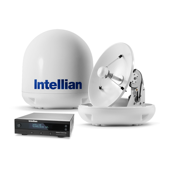
Installation The components of the Intellian i4 Inland are designed as module system so that it is suitable for simple installation on all types of vessels. System Components Antenna Unit The antenna of Intellian i4 Inland is comprised of the following components for optimum search and receive capabilities for satellite signal. - Page 8 Intellian Satellite TV Antenna Systems Antenna Control Unit (ACU) The Antenna Control Unit (ACU) provides the power to the antenna and Front controls the various settings of the antenna. The digital VFD (Vacuum Fluorescent Display) allows for easy operation of the ACU, even in the dark.
- Page 9 Installation Kit Other Components Contains the items required for securing the antenna unit and ACU to the vessel. Components Size ACU Table Mounting Bracket RG6 (Antenna - ACU RF Cable) Antenna RG6 (ACU-Receiver Cable) Power Cable 1.5m Item PC USB Cable 1.5m Self-Tapping Screw Machine Screw...
-
Page 10: Tools Required For Installation
Intellian Satellite TV Antenna Systems Tools Required for Installation Power Drill 11 mm Spanner 10 mm Drill Bit Pencil Power Drill 11 mm Spanner 10 mm Drill Bit Pencil Cross-Head Ø80 mm 5 mm Cross-Head Ø80 mm 5 mm Screwdriver... -
Page 11: Planning The Installation
Planning the Installation Antenna Unit Install the antenna in accordance with the following procedures to insure maximum performance of the antenna. The antenna should be installed in the place where is an all round clear view of the horizon. Please be sure there are no obstacles within 15 degrees above the antenna. - Page 12 You need to follow the power requirements to avoid damaging the system. • Intellian Inland comes with an AC Power Adapter designed to a boat’s power supply rated from 110~220 V AC. • If your Receiver(s) and television(s) require a 110V/240V AC power supply, you will need to install a suitable DC to AC converter to operate the units from your boat’s DC power supply.
-
Page 13: Installation And Mounting Of Antenna
Note: Before installing the antenna, open the radome and remove the shipping constraints from the antenna interior. Reinstall the radome before operating the system. The system will not perform properly if the radome is open. Ø50 cm (19.7”) Figure 8 : Radome Dimension of i4 Inland... - Page 14 RF connector from being exposed to sea water and external shocks. An exposed cable may cause electric shock and cause serious damage to the equipment. 22.86 cm (9”) Figure 9 : Mounting Hole Position of i4 Inland...
- Page 15 Securing Holes for Bolts and Cable Ways Connection of the Cable Make 4 bolt holes of 10mm diameter, one at each corner of a rectangle Remove the rubber cap from RF connector. Connect the RF cable to the drawn as below, and make a circular hole of 80mm diameter at the RF connector under the base plate through the access hole using an center of the rectangle through which the cable will run.
-
Page 16: Installing The Acu
Intellian Satellite TV Antenna Systems Installing the ACU ACU Dimensions Mounting the Antenna Attach the antenna by using the hex head bolts (M8X35L), M8 spring washers, and M8 flat washers supplied. 22.8 cm (9”) Radome Base Deck M8 Flat Washer M8 Spring Washer 17.8 cm (7”) -
Page 17: Selecting Acu Installation Site
Selecting ACU Installation Site The ACU should be installed below deck, in a location that is: • Dry, cool, and ventilated. • Easy access from your main TV viewing area. To Install the ACU 1. The ACU should be installed using the two supplied mounting brackets which allow for a top or bottom mounting configuration. -
Page 18: Connecting The System Cables
Antenna RF Cable (Connecting Antenna - ACU) 3. Connect the DC power cable 1.5m from DC power connector on Intellian provides the Antenna RF Cable (RG-6, 15 m) for connecting the ACU to a power source from 110~220V AC. Antenna and ACU. Due to the signal losses across the length of the RF 4. - Page 19 Twin Receivers Connection You can connect two Receivers for your antenna as shown in the following RF1 RF2 diagram. However, only one of the Receivers can be configured as a two RF3 RF4 satellite receiver. IRD2 (Not Supplied) The other Receiver needs to be configured as a one satellite receiver. The two satellite receiver determines which satellite is tracked, while the Antenna Receiver...
- Page 20 Intellian Satellite TV Antenna Systems Multi-Receivers Connection In order to connect multiple Receivers to the antenna, you will need to purchase a suitable LNB multiswitch. The multiswitch has to be installed RF1 RF2 between the antenna unit and the Receivers as shown in the following RF3 RF4 diagram.
-
Page 21: Connecting The System To A Gps
NMEA 0183GPS tothesystemthroughtheACU’s external GPS connector.To do this you will need a suitable cable to connect your GPS system and the green 2-way ACU GPS connector supplied with your Intellian i4 Inland Satellite TV System. DC 24V... -
Page 22: Adjusting The Lnb Skew Angle (Linear Polarization Only)
It should NOT need to be readjusted if the vessel stays in the same location and is operating on the same satellite. Adjust Skew angle Manually Polarization of your Intellian i4 Inland antenna must be accomplished manually by the following steps. • Remove the upper part of Radome after switching power OFF. -
Page 23: Operation Instruction
Operation Instruction Introduction This section of the handbook describes how to setup your Satellite TV System after installing the ACU. It includes the following functions: • System start up. • Changing the default satellite. • Monitoring the antenna status. • Setting sleep mode. •... -
Page 24: Operating The Acu
Intellian Satellite TV Antenna Systems Operating the ACU ACU Soft Keys Normal Mode Start Up Front With the system installed and power applied, the ACU screen will show the following sequence: BACK 1. Data communication is being established INITIALIZE ACU ENTER between the antenna and the ACU. - Page 25 Changing Target Satellite Advanced Tri-Sat Mode Your antenna is programmed with either two (Dual-Sat mode) or three (Tri- Sat mode) candidates of target satellites as default mode. To 1. Press LEFT soft key for tracking change the target satellite, press LEFT soft key. The target satellite is TRACKING A: DTV101 Satellite B.
- Page 26 Intellian Satellite TV Antenna Systems Monitoring the Current Status of the Antenna While POWER ON to Intellian Inland, ACU displays the status of the antenna. The various ACU displays may be shown according to the current status of the antenna.
-
Page 27: Setup Mode
Setup Mode Sleep Mode Begin Setup Mode If the antenna loses the tracking satellite while in sleep mode, sleep To enter the Setup Mode simply follow the instructions below. mode will be cancelled. 1. Press BACK to enter sleep mode. 1. - Page 28 Intellian Satellite TV Antenna Systems Setting the Satellite Pair You can change the satellite pair if you decide to receive satellite television service from a different service provider. 1. Press YES to enter setup mode. 5. Set satellite B SETUP MODE ? SAT B : DTV119 Press PREV to show previous satellite name.
- Page 29 Setting GPS It is possible to set up and modify the GPS information, which enhances the antenna functionality. 1. Press YES to enter setup mode. 5. Press ENTER to move to next screen. SETUP MODE ? LONGITUDE ###.## E Press BACK to move to previous screen. INPUT 2.
- Page 30 Intellian Satellite TV Antenna Systems Edit Satellite Information It is possible to modify the existing satellite information and input new satellite information into the ACU as well. It is not recommended for a novice satellite service user to use this mode.
- Page 31 13. Input the network ID (NID) for vertical high 9. Input the network ID (NID) for vertical low band. VER LOW 12523 21096 VER HIGH NID 0x0003 band. INPUT INPUT 10. Input the tracking frequency (MHz) and symbol 14. Input the tracking frequency (MHz) and symbol HOR LOW 12523 21096 HOR HIGH 12523 21096 rate (KHz) for horizontal high band.
- Page 32 Intellian Satellite TV Antenna Systems Verification Method* 17. Select the Voltage Supply Method* to LNB. VOLTAGE : AUTO SIGNAL - use only signal level for tracking (AUTO is recommended) PREV SELECT NEXT DVB LOCK - use only DVB Lock signal for tracking...
- Page 33 Setting the Antenna Parameters It is not recommended for a novice satellite service user to use this mode. Consult Intellian for changing antenna parameters. 1. Press YES to enter setup mode. 4. Select the PARAM*. SETUP MODE ? PARAM: SCAN OFFSET PREV - Shows previous parameter.
- Page 34 Intellian Satellite TV Antenna Systems PARAM* Scan Offset Offset RH-LH The scan offset is to offset the angle difference between the The offset RH-LH is to offset the signal difference between black marker on the sub-reflector and the optical sensor.
- Page 35 Setting the LNB Local Frequency It is possible to select a local frequency from ACU. It is not recommended for a novice satellite service user to use this mode. Case1. Single band LNB is used. 1. Press YES to enter setup mode. 4.
- Page 36 Intellian Satellite TV Antenna Systems Case 2. Universal LNB is used (Low band local frequency-9750 MHz/ High band local frequency 10600 MHz). 1. Press YES to enter setup mode. 4. Select the LNB Type* - UNIVERSAL. SETUP MODE ? LNB TYPE : UNIVERSAL PREV - Shows previous LNB type.
- Page 37 Setting the DiSEqC Method DiSEqC selection can be made from ACU. It is not recommended for a novice satellite service user to use this mode. 1. Press YES to enter setup mode. 4. Select the DiSEqC Method* SETUP MODE ? DO NOT USE DISEQC PREV - Shows previous DiSEqC Method.
- Page 38 Intellian Satellite TV Antenna Systems Display Versions This sequence enables you to see what type of antenna and ACU software are installed on your system. 1. Press YES to enter Display Version. 5. Antenna software version and S/N are shown.
- Page 39 Display Power 1. Press YES to enter setup mode. 5. Antenna voltage is shown. SETUP MODE ? ANT POWER : 25.9 V Press center soft key to view Receiver Voltage PREV NEXT and frequency. Press EXIT to return to main setup mode. 2.
- Page 40 Intellian Satellite TV Antenna Systems Setting Remote Control 5. SELECT/ENTER - Registers a key on remote 1. Press YES to enter setup mode. FUNC : SLEEP MODE SETUP MODE ? control. NEXT SELECT EXIT 6. Point remote control to ACU.
- Page 41 Function* 9. REMOTE KEY REGISTED will be displayed if key REMOTE KEY REGISTED CHANGE SAT - Change the target satellite. has been properly registered. SLEEP MODE - Enter sleep mode. CLEAR REGISTERED KEY - Clear registered key. 10. Press NEXT to shows next function. FUNC : CHANGE SAT Press EXIT to return to main setup mode.
- Page 42 Intellian Satellite TV Antenna Systems Setting Antenna Go Position The antenna can be controlled manually by using the ACU. 1. Press YES to enter setup mode. 5. Input position value for elevation (EL) axis. SETUP MODE ? GO TO EL : ##.# + increases the value.
- Page 43 Setting Antenna Move Step The antenna can be moved by 1° step manually by using ACU. 1. Press YES to enter setup mode. 5. Move the antenna in the EL axis. SETUP MODE ? STEP EL : ##.# UP - Move the antenna up. DOWN EXIT DOWN - Move the antenna down.
- Page 44 Intellian Satellite TV Antenna Systems Executing Antenna Diagnosis The antenna status can be checked by reviewing the results of the diagnostic self-test of the antenna. Refer to the following codes to understand the test results. 4. CODE 101 is being tested.
- Page 45 CODE* CODE 101 CODE 107 Data communication between antenna and antenna control unit is Skew System is tested. tested. If failed, check the RF cable. if failed, check the control board, skew motor, and skew sensor. CODE 102 AZ CW limit is tested. CODE 108 Antenna Input Power is tested.
- Page 46 Intellian Satellite TV Antenna Systems Setting Region 1. Press YES to enter setup mode. 5. Select the Region*. SETUP MODE ? REGION : LOS_ANGELES PREV - Shows previous region. PREV SELECT NEXT SELECT - Set the displayed region. NEXT - Shows next region.
- Page 47 Setting the Factory Default Parameters This will restore the antenna back to factory default setting. 1. Press YES to enter setup mode. SETUP MODE ? 2. Press NEXT thirteen times to enter Default SET SAT PAIR ? setting mode. PREV NEXT 3.
-
Page 48: Operation Using Pc Controller Program
Introduction GUI Software of Intellian i3/i3L/i4/i4P has been created for the user to easily set up the antenna by using the user’s personal computer. Using the GUI program enables the user to easily monitor and modify the information of antenna, satellite and GPS. -
Page 49: Program Initialing And Serial Port Setup
Program Initialing and Serial Port Setup Data communication between the ACU and antenna must be established as the first step in order to start setting your antenna. Figure 22 : Setup for Serial Communication Command Buttons • Baud Rate Setting – To display data communication speed. •... -
Page 50: Main Menu
Intellian Satellite TV Antenna Systems Main Menu Antenna Status Monitoring • Search – Antenna is searching for the selected satellite. • Tracking – Antenna is tracking the selected satellite. • Initialize – Antenna or the ACU is initializing. • Unwrap – Antenna is unwinding/winding the cable in the antenna. - Page 51 Set Region 1. Load default: Click “Load Default” button to select satellite library (*.rif file) according to your current region. Figure 24 : Load Regional Library 2. Update default: Click “Update Default” button to open update default dialogue. Click “YES” button to update the system. Figure 25 : Confirm the Update 3.
-
Page 52: Controller Menus
“City GPS”. Pushing “Add City” button stores the GPS information. By selecting the stored region in the list box, the GPS information of each region is displayed. The Intellian satellite TV antenna system utilizes GPS data to locate the satellite faster. Command Buttons •... - Page 53 Setting Satellite Information • Satellite Information The name, longitude and confirmation method of the satellite is displayed when a satellite is selected in the list box. Push “Edit Satellite Information” button to update the information on modifying the value. • DiSEqC When the operation method of DiSEqC is selected to “Change Band”, DiSEqC may be used for updating the local frequency and to “Change Satellite”, for updating the target satellite.
- Page 54 Intellian Satellite TV Antenna Systems Command Buttons • Edit Satellite Information – To modify the satellite information. • Register for Sat A – To register a satellite to satellite A. • Register for Sat B – To register a satellite to satellite B.
- Page 55 Set Tracking Information of Satellite [Primary] Command Buttons • Edit Satellite Information – To change frequency information of the antenna. • Satellite Information – Satellite information consists of frequency, symbol and NID (Network ID) of a transponder in tracking satellite. There are four groups of satellite information.
- Page 56 Intellian Satellite TV Antenna Systems Set Tracking Information of Satellite [Secondary] Voltage DiSEqC Discription 0KHz 22KHz AUTO AUTO AUTO AUTO 13V & 18V and DiSEqC 0KHz & 22KHz tone to LNB AUTO AUTO • • 13V & 18V and DiSEqC 0KHz tone to LNB...
- Page 57 Figure 37 : Antenna Diagnosis Move Antenna and Execute Antenna Diagnosis • Angle of Antenna Two kinds of antenna movement is available. One is to move by the target position and the other is to move by certain amount of angle. The current position (angle) of the antenna is displayed as “Current”...
- Page 58 Intellian Satellite TV Antenna Systems Set Antenna Parameters for Control It is not recommended for a novice satellite service user to use this mode. Consult Intellian for changing antenna parameters. Command Buttons • Set Control Parameter – To register parameters value.
- Page 59 Parameter Setting - To set antenna parameter values. Scan Offset The scan offset is to offset the angle difference between the Offset RH-LH The offset RH-LH is to offset the signal difference between black marker on the sub-reflector and the optical sensor. RHCP and LHCP.
-
Page 60: Preparation For Transportation
5. Cover upper part of radome. Be careful not to touch the reflector when assembling upper part of radome. 6. Pack Intellian i4 Inland into the original package box. NOTE : Don’t rotate it quickly, or you may damage the antenna limit system. -
Page 61: Warranty
All products returned to Intellian Technologies, during the warranty period must be accompanied by a Service Case reference number issued by the dealer/distributor from Intellian Technologies, and (where applicable) a copy of the purchase receipt as a proof of purchase date, prior to shipment. Alternatively, you may bring the product... -
Page 62: Appendix : Technical Specification
Intellian Satellite TV Antenna Systems Appendix : i4 Inland Technical Specification General Antenna system performance Approvals Frequency Ku-band (10.7 to 12.75 GHz) CE – conforms to EU Directive 89/336/EEC FCC – verified to CFR47:Part 15 Minimum EIRP 49dBW Dimensions Azimuth range 680°...
Need help?
Do you have a question about the i4 Inland and is the answer not in the manual?
Questions and answers