Table of Contents

Related Manuals for Cypress Semiconductor CY3215-DK


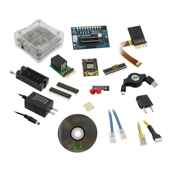
Summary of Contents for Cypress Semiconductor CY3215-DK
- Page 1 CY3215-DK ® PSoC 1 In-Circuit Emulator Development Kit Guide Doc. # 001-66514 Rev. *B Cypress Semiconductor 198 Champion Court San Jose, CA 95134-1709 Phone (USA): 800.858.1810 Phone (Intnl): 408.943.2600 http://www.cypress.com...
- Page 2 © Cypress Semiconductor Corporation, 2011-2012. The information contained herein is subject to change without notice. Cypress Semiconductor Corporation assumes no responsibility for the use of any circuitry other than circuitry embodied in a Cypress product. Nor does it convey or imply any license under patent or other rights. Cypress products are not warranted nor intended to be used for medical, life support, life saving, critical control or safety applications, unless pursuant to an express written agreement with Cypress.
-
Page 3: Table Of Contents
PSoC Programmer ....................25 4. Code Examples My First Code Example .....................28 4.1.1 Project Objective ....................28 4.1.2 Creating My First PSoC 1 Project ..............28 4.1.3 Verify Output ....................36 CY3215-DK PSoC 1 In-Circuit Emulator Development Kit Guide, Doc. # 001-66514 Rev. *B... - Page 4 Contents CY3215-DK PSoC 1 In-Circuit Emulator Development Kit Guide, Doc. # 001-66514 Rev. *B...
-
Page 5: Introduction
Thank you for your interest in the CY3215-DK PSoC 1 In-Circuit Emulator Development Kit. You can use this kit with PSoC Designer™ or PSoC Programmer. The CY3215-DK provides debugging functionality that requires two-way communication between the in-circuit emulator (ICE) and your computer. -
Page 6: Additional Learning Resources
For more information on CY3250-29xxxQFN ICE Pod Schematic: ■ http://www.cypress.com/?rID=3451 For more information on CY3250-FLEXCABLE Mechanical Layout Drawing: ■ http://www.cypress.com/?rID=3451 For more information on CY3250-29xxxQFN ICE Pod Mechanical Layout Drawing: ■ http://www.cypress.com/?rID=3451 CY3215-DK PSoC 1 In-Circuit Emulator Development Kit Guide, Doc. # 001-66514 Rev. *B... -
Page 7: Document History
Click the File icon and then click Open. Displays an equation: Times New Roman 2 + 2 = 4 Text in gray boxes Describes cautions or unique functionality of the product. CY3215-DK PSoC 1 In-Circuit Emulator Development Kit Guide, Doc. # 001-66514 Rev. *B... - Page 8 Introduction CY3215-DK PSoC 1 In-Circuit Emulator Development Kit Guide, Doc. # 001-66514 Rev. *B...
-
Page 9: Getting Started
Getting Started This chapter describes how to install the CY3215-DK PSoC 1 In-Circuit Emulator Development Kit. Kit Installation To install the CY3215-DK kit, follow these steps: 1. Insert the kit CD into the CD/DVD drive of your PC. The CD is designed to auto-run and the kit installer startup screen appears. - Page 10 5. On the Product Installation Overview screen, select the installation type that best suits your requirement. The drop-down menu has three options: Typical, Complete, and Custom, as shown in Figure 2-4. 6. Click Next to start the installation. CY3215-DK PSoC 1 In-Circuit Emulator Development Kit Guide, Doc. # 001-66514 Rev. *B...
- Page 11 Figure 2-5. 8. Wait until all the packages are downloaded and installed successfully. Figure 2-5. Installation Page CY3215-DK PSoC 1 In-Circuit Emulator Development Kit Guide, Doc. # 001-66514 Rev. *B...
-
Page 12: Psoc Designer
Figure 2-6. Installation Complete Page After software installation, verify that you have all hardware and drivers set up for the CY3215-DK kit by connecting the kit to your PC via its USB interface. Because this is the first time you have con- nected this board to this PC, initial drivers are installed. - Page 13 Note For more details on PSoC Designer, see the PSoC Designer IDE Guide located at: <Install_directory>:\PSoC Designer\<version>\Documentation. Additional Learning Resources on page 5 for links to PSoC Designer training. The PSoC Designer quick start guide is available at: http://www.cypress.com/?rID=47954 CY3215-DK PSoC 1 In-Circuit Emulator Development Kit Guide, Doc. # 001-66514 Rev. *B...
-
Page 14: Psoc Programmer
4. Click the Program button to program the selected PSoC 1 device. 5. Close PSoC Programmer. Note For more details on PSoC Programmer, see the user guide at the following location: <Install_directory>\Cypress\Programmer\<version>\Documents CY3215-DK PSoC 1 In-Circuit Emulator Development Kit Guide, Doc. # 001-66514 Rev. *B... -
Page 15: Using Ice-Cube Connector
Using ICE-Cube Connector Introduction The CY3215-DK is used for prototyping and developing applications with PSoC Designer IDE. This kit supports in-circuit emulation and the software interface allows access to the contents of specific memory locations. 3.1.1 Software Installation After the physical connection is made, you are ready to configure the internal connection from the computer to the ICE. - Page 16 8. On successful connection, you receive a notification in the Output tab of the Status window; a green indicator displays Connected in the lower-right corner of the program. Figure 3-2. PSoC Designer Connected with ICE-Cube CY3215-DK PSoC 1 In-Circuit Emulator Development Kit Guide, Doc. # 001-66514 Rev. *B...
-
Page 17: Connecting The Ice-Cube
Simply plug a pod into the cir- cuit without connecting it to an ICE base station. The pod power LED lights up when it is powered and operational. CY3215-DK PSoC 1 In-Circuit Emulator Development Kit Guide, Doc. # 001-66514 Rev. *B... - Page 18 Plastic Mask: The plastic mask is used to orient the foot. Plastic masks are provided to expose ■ only the pins that connect to the foot. Figure 3-7. Plastic Mask CY3215-DK PSoC 1 In-Circuit Emulator Development Kit Guide, Doc. # 001-66514 Rev. *B...
- Page 19 6. Connect the other end of the flex cable to the ICE-Cube pod connector, as shown in Figure 3-6. 7. Start debugging the project, as explained in Debug a Project on page 20. Figure 3-9. Flex Pod Connected to ICE-Cube Pod CY3215-DK PSoC 1 In-Circuit Emulator Development Kit Guide, Doc. # 001-66514 Rev. *B...
-
Page 20: Connect Using A Backward Compatibility Adapter
Connect using a Backward Compatibility Adapter A backward compatibility adapter can be used to debug and program the PSoC 1 chips. Figure 3-10. Backward Compatibility Adapter Figure 3-11. Connector in ICE-Cube CY3215-DK PSoC 1 In-Circuit Emulator Development Kit Guide, Doc. # 001-66514 Rev. *B... -
Page 21: Debug A Project
5. Click on Connect/Disconnect or press F9. 6. Right-click on a line in the project from where the debugging process should start. The Insert/ Delete Breakpoint option appears. CY3215-DK PSoC 1 In-Circuit Emulator Development Kit Guide, Doc. # 001-66514 Rev. *B... - Page 22 Debug > Step ASM (or press Shift + F10): If the current line is C code, the line is located in the first file and that line is executed CY3215-DK PSoC 1 In-Circuit Emulator Development Kit Guide, Doc. # 001-66514 Rev. *B...
-
Page 23: Break Points
Registers) and in the notification area at the bottom of PSoC Designer. The other four areas can be viewed in the Memory Window (Debug > Windows > Memory). Select one of the four memory areas from the Address Space box. CY3215-DK PSoC 1 In-Circuit Emulator Development Kit Guide, Doc. # 001-66514 Rev. *B... -
Page 24: Watch Variables
To set watch variables, right-click a variable in a source file and select Add Watch. You can also select Global Variables. Right-click Add, Delete, or Properties in the Watch/Global Name window to add, delete, or modify values. Figure 3-18. Watch Variables Window CY3215-DK PSoC 1 In-Circuit Emulator Development Kit Guide, Doc. # 001-66514 Rev. *B... -
Page 25: Trace
WARNING: The time taken to execute a system supervisory call (SSC) such as FlashRead/Write, Table Read, and Erase Block is significantly more while emulating a code through ICE-Cube when compared to the time taken when running the code on chip. CY3215-DK PSoC 1 In-Circuit Emulator Development Kit Guide, Doc. # 001-66514 Rev. *B... -
Page 26: Psoc Programmer
7. Select Reset under programming mode. 8. Apply power to the target board. 9. Click Program to start device programming. 10.The action window reports the status and success of programming. CY3215-DK PSoC 1 In-Circuit Emulator Development Kit Guide, Doc. # 001-66514 Rev. *B... - Page 27 Using ICE-Cube Connector Figure 3-22. Hardware Configuration with ICE-Cube CY3215-DK PSoC 1 In-Circuit Emulator Development Kit Guide, Doc. # 001-66514 Rev. *B...
- Page 28 Using ICE-Cube Connector CY3215-DK PSoC 1 In-Circuit Emulator Development Kit Guide, Doc. # 001-66514 Rev. *B...
-
Page 29: Code Examples
4. Click Browse and navigate to the directory in which the project should be created. Figure 4-1. New Project Window 5. Click OK. The Select Project Type window opens. CY3215-DK PSoC 1 In-Circuit Emulator Development Kit Guide, Doc. # 001-66514 Rev. *B... - Page 30 7. The Device Catalog window opens. Click on the PSoC tab and scroll down to the CY8C29466, CY8C29566,… section. 8. For this project, click CY8C29466-24PXI and then click Select; see Figure 4-3. CY3215-DK PSoC 1 In-Circuit Emulator Development Kit Guide, Doc. # 001-66514 Rev. *B...
- Page 31 Figure 4-3. Device Catalog Window 9. Under Generate 'Main' File Using:, select C, then click OK. 10.By default, the project opens in chip view, as shown in Figure 4-4. CY3215-DK PSoC 1 In-Circuit Emulator Development Kit Guide, Doc. # 001-66514 Rev. *B...
- Page 32 11. In the User Modules window, expand the PWMs folder. In this folder, right-click on PWM8 and select Place. The user module (UM) is placed in the first available digital block. Figure 4-5. User Modules Window CY3215-DK PSoC 1 In-Circuit Emulator Development Kit Guide, Doc. # 001-66514 Rev. *B...
- Page 33 (LUT) on Row_0_Output3. Figure 4-7. Route PWM CompareOut Signal to P2[0] 14.Double-click the LUT, the Digital Interconnect window opens. 15.In this window, enable Row_0_Output_0_Drive_0 to connect to GlobalOutEven_0. CY3215-DK PSoC 1 In-Circuit Emulator Development Kit Guide, Doc. # 001-66514 Rev. *B...
- Page 34 Place; this adds the UM to the project. This UM does not use digital or analog blocks. It appears in Workspace Explorer > Example_My_First_PSoC_Project[CY8C29466-24PXI] > Example_My_First_PSoC_Project[Chip] > Loadable Configurations > example_my_first_psoc_project - 2 User Modules. CY3215-DK PSoC 1 In-Circuit Emulator Development Kit Guide, Doc. # 001-66514 Rev. *B...
- Page 35 20.Configure the LED properties, as shown in the following figure. Figure 4-11. LED User Module Properties 21.Configure the Global Resources window to match the following figure. Figure 4-12. Global Resources Window CY3215-DK PSoC 1 In-Circuit Emulator Development Kit Guide, Doc. # 001-66514 Rev. *B...
- Page 36 25.Connect the ICE-Cube to the PC. Connect the ICE-Cube to the MiniEval board, as explained in Connecting the ICE-Cube on page 26.In PSoC Designer, select Debug > Connect/Disconnect to connect the ICE to PSoC Designer. Figure 4-14. Connecting ICE to PSoC Designer CY3215-DK PSoC 1 In-Circuit Emulator Development Kit Guide, Doc. # 001-66514 Rev. *B...
-
Page 37: Verify Output
Step Into command enters the function calls as well. For more details on debugging, debug menu options, and debug strategies, see Help > Help Topics > Debugger. CY3215-DK PSoC 1 In-Circuit Emulator Development Kit Guide, Doc. # 001-66514 Rev. *B... - Page 38 Code Examples CY3215-DK PSoC 1 In-Circuit Emulator Development Kit Guide, Doc. # 001-66514 Rev. *B...
Need help?
Do you have a question about the CY3215-DK and is the answer not in the manual?
Questions and answers