
Related Manuals for Cypress Semiconductor PSoC 1 FirstTouch CY3270


Summary of Contents for Cypress Semiconductor PSoC 1 FirstTouch CY3270
- Page 1 CY3270 ® PSoC 1 FirstTouch™ Kit Guide Document No. 001-15945 Rev. *D Cypress Semiconductor 198 Champion Court San Jose, CA 95134-1709 Phone (USA): 800.858.1810 Phone (Intnl): 408.943.2600 http://www.cypress.com...
- Page 2 © Cypress Semiconductor Corporation, 2007-2011. The information contained herein is subject to change without notice. Cypress Semiconductor Corporation assumes no responsibility for the use of any circuitry other than circuitry embodied in a Cypress product. Nor does it convey or imply any license under patent or other rights. Cypress products are not warranted nor intended to be used for medical, life support, life saving, critical control or safety applications, unless pursuant to an express written agreement with Cypress.
-
Page 3: Table Of Contents
Contents 1. Introduction Kit Contents ..........................6 Additional Learning Resources....................6 1.2.1 Reference Documents ....................6 Document History ........................7 Document Conventions ......................7 2. Getting Started Introduction ..........................9 CD Installation ..........................9 PSoC Designer ........................14 PSoC Programmer .........................15 Install Hardware........................15 Run CapSense Touch Sensing Design ..................16 3. - Page 4 Contents 5.3.2 Firmware Architecture....................56 Multifunction Expansion Card Temperature Sensor............... 57 5.4.1 Device Configuration ....................58 5.4.2 Firmware Architecture....................59 A. Appendix Schematic..........................61 A.1.1 First Touch PC Bridge Schematic ................61 A.1.2 First Touch Multifunction Card Schematic ..............62 Board Layout ..........................
-
Page 5: Introduction
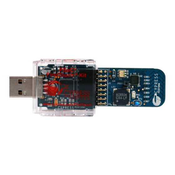
Introduction ® Thank you for your interest in the CY3270 PSoC 1 FirstTouch™ Kit (FTK). You can design your own projects with Cypress's easy-to-use Integrated Development Environment (IDE), PSoC Designer™, or by altering sample projects provided along with this kit. The CY3270 PSoC 1 FTK is described in the Help guides and examples projects that are available. -
Page 6: Kit Contents
Introduction Chapter 2 describes the installation and configuration of the CY3270 PSoC 1 FTK. Chapter 3 describes the kit operation. It explains the programming of a PSoC 1 device with the PSoC Programmer, and the usage of the kit with the help of an example project. Chapter 4 describes the hardware operation. -
Page 7: Document History
Introduction Document History PDF Creation Origin of Revision Description of Change Date Change 08/17/2007 New document 02/08/2011 RKPM Updated template. 02/16/2011 GNKK Formatted page layout in TOC. Updated link in CD Installation section. Removed reference to PSoC Express from 02/22/2011 RKPM Copyright information. - Page 8 Introduction CY3270 PSoC® FirstTouch™ Kit Guide, Document No. 001-15945 Rev. *D...
-
Page 9: Getting Started
Getting Started Introduction This chapter describes how to install and configure the CY3270 PSoC 1 FTK. CD Installation To install the CY3270 PSoC 1 FTK, follow these steps: 1. Insert the kit CD into the CD drive of your PC. The CD is designed to auto-run and the kit installer menu appears. - Page 10 Getting Started Figure 2-1. Kit Installer Menu Note If auto-run does not execute, double-click cyautorun.exe file on the root directory of the CD as shown in Figure 2-2. Figure 2-2. Root Directory of the CD 3. The InstallShield Wizard screen appears. On this screen, choose the folder location to install the setup files.
- Page 11 Getting Started Figure 2-3. InstallShield Wizard 5. On the Product Installation Overview screen, select the installation type that best suits your requirement. The drop-down menu has three options - Typical, Complete, and Custom, as shown in Figure 2-4. 6. Click Next to start the installation. Figure 2-4.
- Page 12 Getting Started 8. A green check mark appears next to each package as it is downloaded and installed (see Figure 2-5. 9. Wait until all the packages are downloaded and installed successfully. Figure 2-5. Installation Page CY3270 PSoC® FirstTouch™ Kit Guide, Document No. 001-15945 Rev. *D...
- Page 13 Getting Started 10.Click Finish to complete the installation of the kit installer as shown in Figure 2-6. Figure 2-6. Installation Completion Page After installing the software, verify that you have all hardware and drivers setup for the CY3270 PSoC 1 FTK by connecting the kit to your PC through its USB interface. As this is the first time you connect the board to this PC, initial drivers get installed.
-
Page 14: Psoc Designer
Getting Started PSoC Designer 1. Click Start > All Programs > Cypress > PSoC Designer <version> > PSoC Designer <ver- sion> (Figure 2-7) 2. Click File > New Project to create a new project on the PSoC Designer <version> menu or click File >... -
Page 15: Psoc Programmer
Getting Started PSoC Programmer 1. Click Start > All Programs > Cypress > PSoC Programmer <version>> PSoC Programmer <version> (Figure 2-8). 2. Select the MiniProg from the port selection as shown in Figure 2-8. Figure 2-8. PSoC Programmer Window 3. Click File Load to load the hex file. 4. -
Page 16: Run Capsense Touch Sensing Design
Getting Started Run CapSense Touch Sensing Design To install the kit hardware and run the CapSense touch sensing design, continue as follows: 1. Remove both end caps from the FTPC Bridge and then connect the FTMF Expansion Card into the header of the FTPC Bridge such that ‘Cypress Perform’ is visible on both boards. Insert the assembled kit in your computer’s USB port. -
Page 17: Kit Operation
Kit Operation Introduction The CY3270 PSoC 1 FTK examples help you develop applications using the PSoC 1 family of devices. The kit is designed to showcase how PSoC 1 can be used to easily develop temperature, CapSense, light, and proximity sensing applications. 3.1.1 MultiFunction Expansion Card (FTMF) The FTMF card is connected to the PC bridge as shown in... -
Page 18: Capsense Touch Sensing Demonstration (Default)
Kit Operation Figure 3-2. FTMF Expansion Card 3.2.1 CapSense Touch Sensing Demonstration (Default) The pre-programmed CapSense touch sensing demonstration shows how to use the CapSense touch sensing slider at the end of the board to control LED color. Run your finger across the CapSense touch sensing slider and notice how the color of the LED changes. -
Page 19: Hardware
Hardware System Block Diagram The CY3270 PSoC 1 FTK has the following sections. PC bridge (FTPC bridge) ■ Multifunction card ■ Figure 4-1. System Block Diagram for FirstTouch PC Bridge (FTPC Bridge) USB Port Blue LED PSoC Programming CY8C24894 and Interface Connector CY3270 PSoC®... -
Page 20: Ftpc Bridge (First Touch Pc Bridge)
Hardware Figure 4-2. System Block Diagram for First Touch Multifunction Card Ambient Light Detector Blue LED Programming and Interface Connector PSoC CY8C21434 CapSense Slider RGB Clusters CapSense Proximity Sensor Thermistor FTPC Bridge (First Touch PC Bridge) The PC bridge consists of the CY8C24894 Hub. It contains a 16-pin connector to connect to the MultiFunction Board for application data exchange.The FTPC Bridge is the interface bridge between the expansion card, your PC, and the various applications. -
Page 21: Led Usage
Hardware 4.2.1 LED Usage Blue LED The blue LED blinks fast when the bridge is first connected to the USB port of a PC. After hot plug and play is established, it blinks at a periodic interval to indicate that the hub is enumerated and functioning normally. - Page 22 Hardware Note that the CY8C24894 PSoC device is the only active component in the entire circuit. This single PSoC handles all communications between the applications, USB, and expansion card interfaces. The FirstTouch expansion card connects to the FTPC bridge through the 8×2 expansion port (this is a built-in port on the bridge).
-
Page 23: Expansion Card Overview
Hardware Expansion Card Overview The FirstTouch expansion card is designed to plug and play with the FTPC bridge. All power for the included expansion cards is provided by the FTPC bridge directly from the USB bus. No other power supply is necessary when an expansion card is connected to the FTPC bridge. Connection to the FTPC expansion port is through the 8×2 pin header on the expansion card. - Page 24 Hardware The FTMF expansion card uses a standard FirstTouch expansion header to connect to the First- Touch RF expansion board or other target hardware. Figure 4-5. FTMF Expansion Card Expansion Header Signals Note that the 8×2 pin expansion header also includes four GPIO connections labeled P02 to P05. These are hard wired to four unused Port 0 I/O pins on the CY8C21434 host and allow you to easily connect the FTMF expansion card to your specific hardware or sensors.
- Page 25 Hardware Figure 4-7. CapSense Slider Schematic CSB1 CSENSE1 CS GND Cap Sense FTMF CSB2 CSENSE2 CS GND Cap Sense FTMF CSB3 CSENSE3 CS GND Cap Sense FTMF CSB4 CSENSE4 CS GND Cap Sense FTMF CSB5 CSENSE5 CS GND Cap Sense FTMF CSB6 CSENSE6 CS GND...
- Page 26 Hardware Figure 4-8. Light Sensor Schematic VEXP + PR1 Ambient Light LX1972A Detector LSENSE 4.99K 1% Ambient light sensors consist of a filter to sample visible light, a photo diode for detection of bright- ness, a digital filter, and a digital/analog converter. They are able to detect the intensity of surround- ing light.
- Page 27 Hardware Figure 4-10. CY8C21434 Master VEXP VEXP VEXP 2.2K 2.2K ISSP_XRES XRES TSENSE P0_0 P0_1 P0_2 ISSP_DAT P0_3 P1_0 ISSP_CLK P0_4 P1_1 LED_BLUE P0_5 P1_2 LSENSE LED_RED P0_6 P1_3 ZVREF LED_GRN P0_7 P1_4 I2C_SDA P1_5 ALARM P1_6 I2C_SCL PRX1 P1_7 P2_0 CSENSE1 P2_1...
- Page 28 Hardware Table 4-1. FTMF PSoC Pin Assignments Pin Number Port Number Design Function P3[2] Unused / no-connect P2[0] CapSense proximity antenna pad (PRX1) P2[2] CapSense slider element 2 P2[4] CapSense slider element 4 P2[6] CapSense slider element 6 P0[0] Thermistor temperature sensor analog input P0[2] User A/D-GPIO P0[4]...
-
Page 29: Code Examples
Code Examples My First Code Example 5.1.1 Project Objective This code example demonstrates the CapSense feature of the FTMF board. The color of the LED changes with respect to the position of finger on the board. The code example contains the following User Modules: CSD: The CSD module is used to scan the CapSense sensors and determine the finger position ■... -
Page 30: Flowchart
Code Examples 5.1.2 Flowchart Start Enable Global Interrupts Initialize CSD, LED, EzI2Cs Module Read Finger Position on CapSense Slider If finger position is Turn ON Blue on slider positions CSB1- CSB3 If finger position is Turn ON Green on slider positions CSB4, CSB5 If finger position is on slider... - Page 31 Code Examples Figure 5-1. New Project Window 5. Click OK. The Select Project Type window opens. 6. In this window, under Select Target Device, click View Catalog. Figure 5-2. Select Project Type Window 7. The Device Catalog window opens. Click the All Devices tab. 8.
- Page 32 Code Examples Figure 5-3. Device Catalog Window CY3270 PSoC® FirstTouch™ Kit Guide, Document No. 001-15945 Rev. *D...
- Page 33 Code Examples 9. Under Generate 'Main' File Using, select C and click OK. 10.By default, the project opens in chip view. Figure 5-4. Default View 11. Now place and configure the modules required for this design. Connect the modules together and to the pins of the PSoC.
- Page 34 Code Examples 12.In the Cap Sensors folder, right click on CSD and select Place. Figure 5-6. User Modules Window-CSD Select 13.A pop-up window opens with the configuration of the CSD module to be selected. Select CSD without clock prescaler as the default module. Click OK. Figure 5-7.
- Page 35 Code Examples 14.The User Module (UM) CSD is placed in the analog and digital blocks respectively. Figure 5-8. CSD User Module Placement 15.Rename CSD_1 as CSD and configure the CSD properties. Figure 5-9. Configure CSD Parameters Window CY3270 PSoC® FirstTouch™ Kit Guide, Document No. 001-15945 Rev. *D...
- Page 36 Code Examples 16.Right click on the CSD user module icon and select the CSD Wizard option to assign pins to the sensors properly. Figure 5-10. Select CSD Wizard Window CY3270 PSoC® FirstTouch™ Kit Guide, Document No. 001-15945 Rev. *D...
- Page 37 Code Examples 17.Open the CSD Wizard window. Figure 5-11. Default CSD Wizard Window 18.The following screenshot shows the default settings in the Global Settings window. Figure 5-12. Default Global Settings Window CY3270 PSoC® FirstTouch™ Kit Guide, Document No. 001-15945 Rev. *D...
- Page 38 Code Examples 19.Configure the parameters in the window. Figure 5-13. Configured Global Settings Window 20.Click on Slider in the CSD wizard window. Following are the default settings in the Sensors Set- tings window. Figure 5-14. Default Sensors Settings 21.Configure the parameters in the Sensors Settings window. Figure 5-15.
- Page 39 Code Examples 22.To assign the sensor on the particular pin, click and drag from the sensor block to the required pin in the Pin Assignment window. Drag and drop S1 (0) of the slider to pin P2 [0]. The assignment of the sensor pins can be done in either Table Pin Assignment View (Figure 5-16) or Chip Pin...
- Page 40 Code Examples 23.Similarly, assign all the sensors from S1(1) through S1(7) to pins P2[1] through P2[7] and click Figure 5-18. Sensors Assigned – Table Pin Assignment View CY3270 PSoC® FirstTouch™ Kit Guide, Document No. 001-15945 Rev. *D...
- Page 41 Code Examples 24.All the assigned sensors can be seen in Chip Pin Assignment View. Figure 5-19. Sensors Assigned - Chip Pin Assignment View CY3270 PSoC® FirstTouch™ Kit Guide, Document No. 001-15945 Rev. *D...
- Page 42 Code Examples 25.After configuration in the CSD Wizard window, the pins to which sensors are assigned can be seen in the Chip Level diagram. Figure 5-20. CSD Component 26.In the User Modules window, expand the Digital Comm folder, right click on EzI2Cs, and select Place to place an EzI2Cs in the design.
- Page 43 Code Examples 27.The EzI2Cs module does not require any digital or analog blocks for placement. It requires either (configurable) P1[0] and P1[1] or P1[5] and P1[7] port pins to operate as SCL and SDA. 28.Configure the EzI2Cs properties: Figure 5-22. EzI2Cs Properties CY3270 PSoC®...
- Page 44 Code Examples 29.The EzI2Cs module can be seen in the Chip window. Figure 5-23. EzI2Cs Component CY3270 PSoC® FirstTouch™ Kit Guide, Document No. 001-15945 Rev. *D...
- Page 45 Code Examples 30..In the User Modules window, expand the Misc Digital folder, right click on LED, and select Place to place the LED. Figure 5-24. User Modules Window- LED Select 31.Configure LED properties and rename as LED_BLUE. Figure 5-25. LED Properties CY3270 PSoC®...
- Page 46 Code Examples 32.After the configuration, LED_BLUE is assigned and is visible in the Chip Level diagram. Figure 5-26. LED User Module Placement CY3270 PSoC® FirstTouch™ Kit Guide, Document No. 001-15945 Rev. *D...
- Page 47 Code Examples 33.Place two more LED modules and configure as shown in the following screenshots. Figure 5-27. LED Red Properties. Figure 5-28. LED Green Properties CY3270 PSoC® FirstTouch™ Kit Guide, Document No. 001-15945 Rev. *D...
- Page 48 Code Examples 34.Place LED_GREEN, LED_RED, and LED_BLUE in their respective ports. Figure 5-29. All LEDs Placed 35.Keep the default values for the Global Resources window. Figure 5-30. Global Resources Window CY3270 PSoC® FirstTouch™ Kit Guide, Document No. 001-15945 Rev. *D...
- Page 49 Code Examples 36.Open the existing main.c file within Workspace Explorer. Replace the existing main.c content with the content of the embedded Example_ My_First_PSoC_Project_Main.c file, which is attached with this document. Figure 5-31. Workspace Explorer Window 37.Save the project. 38.Build the project; Build > Generate/Build 'Example_My_First_PSoC_Project' Project. 39.Connect the FirstTouch Multifunction Expansion(FTMF) card to the PC Bridge.
- Page 50 Code Examples Figure 5-33. Program Part Window 44.In the Program Part window, set up the following: a. In the Port Selection drop down box, FirstTouch/<MiniProg Number> is selected and it is 'Connected' b. Acquire Mode: Reset c. Verification: Off d. Power Settings: 5.0 V 45.Click on the Program button to start programming the board.
-
Page 51: Multifunction Expansion Card Light Sensor
Code Examples 5.1.3.1 Verify Output 1. Connect the PC Bridge to PC. 2. Connect the MultiFunction card to the PC bridge. 3. Move your finger across the CapSense slider to detect LED color change. ■ When the finger position is on slider position CSB1-CSB3, the LED emits the color blue. When the finger position is on the slider position CSB4 or CSB5, the LED emits the color green. -
Page 52: Device Configuration
Code Examples 5.2.1 Device Configuration The chip level view of the code example, after placing all the required user modules, is shown in Figure 5-37 Figure 5-37. Device Configuration of Light Sensor CY3270 PSoC® FirstTouch™ Kit Guide, Document No. 001-15945 Rev. *D... -
Page 53: Firmware Architecture
Code Examples 5.2.2 Firmware Architecture 5.2.2.1 Flowchart Start Enable Global Interrupts Initialize ADC, LED, EzI2Cs Modules Get ADC Data from Light Sensor Turn ON Blue If ADC_Data >ZERO Turn OFF Blue 5.2.2.2 Verify Output 1. When light is present, the LED is switched ON 2. -
Page 54: Multifunction Expansion Card Proximity Sensor
Code Examples Figure 5-38. Light Sense Output MultiFunction Expansion Card Proximity Sensor This code example demonstrates the capacitive sensing and proximity detection capability of Cypress's PSoC technology. Proximity detection requires that you use the supplied blue proximity antenna. Insert the bare end of the wire in the PRX1 connector located in the middle of the board. As you move your finger near and far from the proximity detection antenna, the red and green LEDs turn on and off. -
Page 55: Device Configuration
Code Examples 5.3.1 Device Configuration The chip level view of the code example, after placing all the required user modules, is shown in Figure 5-39. Figure 5-39. Device Configuration of Proximity Sensor CY3270 PSoC® FirstTouch™ Kit Guide, Document No. 001-15945 Rev. *D... -
Page 56: Firmware Architecture
Code Examples 5.3.2 Firmware Architecture 5.3.2.1 Flowchart Start Enable Global Interrupts Initialize CSD, LED, EzI2Cs Modules Get Finger Position around Proximity Sensor Turn ON Green If Sensor_data >ZERO Turn ON Red LED 5.3.2.2 Verify Output 1.The color changes when the finger is taken near the proximity antenna 2.The color remains red when no data is received from the antenna CY3270 PSoC®... -
Page 57: Multifunction Expansion Card Temperature Sensor
Code Examples Figure 5-40. Proximity Antenna Output Multifunction Expansion Card Temperature Sensor This code example demonstrates the temperature sensing, thermistor reading, and calibrating capabilities of the PSoC device. Depending upon the temperature range within which a particular temperature reading is recorded, different colored LEDs (red, green, and blue) are turned ON or OFF. -
Page 58: Device Configuration
Code Examples 5.4.1 Device Configuration The chip level view of the code example, after placing all the required user modules, is shown in Figure 5-41 Figure 5-41. Device Configuration of Temperature Sensor CY3270 PSoC® FirstTouch™ Kit Guide, Document No. 001-15945 Rev. *D... -
Page 59: Firmware Architecture
Code Examples 5.4.2 Firmware Architecture 5.4.2.1 Flowchart Start Enable Global Interrupts Initialize ADC, LED, EzI2Cs Module Get ADC Value Convert ADC Value to Temperature Value If temperature Turn ON Blue is between -10 C to 16 C If temperature is Turn ON Green between 16 C to 28 C... - Page 60 Code Examples Figure 5-42. Temperature Reading and Updated LED Status CY3270 PSoC® FirstTouch™ Kit Guide, Document No. 001-15945 Rev. *D...
-
Page 61: Appendix
Appendix The schematic board layouts and BOM are available on the CY3270-FTK kit CD or at this location: <Install_directory>:\Cypress\CY3270-FTK\<version>\Hardware. Schematic A.1.1 First Touch PC Bridge Schematic XRES894 CLK894 DAT894 ISSP894 ISSP894 ISSP-RADON 10 uFd 10v 10 uFd 10v 0805 0805 0805 0805 0805... -
Page 62: First Touch Multifunction Card Schematic
NOTE: This Expansion Board Does Not Have An Onboard Voltage Regulator - DO NOT Power With > 5Vdc S T-23 ALARM 2N7002 VEXP PCB:PDCR-9 02 CYPRESS SEMICONDUCTOR © 2007 10K 1% Title FIRST TOUCH MULTI FUNCTION BOARD Size Document Number REF-14209... -
Page 63: Board Layout
Appendix Board Layout A.2.1 PDCR-9402 Primary side A.2.2 PDCR-9402 Secondary Side A.2.3 Assembly Drawing of First touch Multifunction Card (Primary side) CY3270 PSoC® FirstTouch™ Kit Guide, Document No, 001-15945 Rev. *D... -
Page 64: Assembly Drawing Of First Touch Multifunction Card (Secondary Side)
Appendix A.2.4 Assembly Drawing of First touch Multifunction Card (Secondary Side) A.2.5 PDCR-9403 Primary Side A.2.6 PDCR-9403 Secondary Side CY3270 PSoC® FirstTouch™ Kit Guide, Document No, 001-15945 Rev. *D... -
Page 65: Assembly Drawing For Firsttouch Pc Bridge
Appendix A.2.7 Assembly Drawing for FirstTouch PC Bridge CY3270 PSoC® FirstTouch™ Kit Guide, Document No, 001-15945 Rev. *D... -
Page 66: Bom
Appendix A.3.1 FirstTouch Multifunction Board Item Qty Reference Description Manufacturer Mfr Part Number CAP 10000 PF 16 V CERM X7R 0603 Panasonic ECJ-1VB1C103K C2,C3 CAP .10 UF 10 V CERAMIC X5R 040 Kemet C0402C104K8PACTU CAP 4.7 UF 16 V Tantalum 3216 Nichicon F931C475MAA Lumex Opto/... -
Page 67: Firsttouch Pc Bridge
MCR10EZHJ101 RES 1.0 KΩ 1/8W 5% 0805 SMD Rohm MCR10EZHJ102 PSoC Mixed-Signal Array Cypress Semiconductor CY8C24894-24LFXI PRINTED CIRCUIT BOARD Cypress Semiconductor PDCR-9403 Rev ** LABEL1 Serial Number LABEL2 PCA LABEL 121R-40300 Rev ** DO NOT INSTALL HEADER 0.1" SQ 5-PIN SMD AU NA...
Need help?
Do you have a question about the PSoC 1 FirstTouch CY3270 and is the answer not in the manual?
Questions and answers