Table of Contents
Advertisement
Quick Links
NuMaker-emWin-RDK-N9H20
ARM® ARM926EL-S Based
32-bit Microprocessor
NuMaker-emWin-RDK-N9H20
User Manual
The information described in this document is the exclusive intellectual property of
Nuvoton Technology Corporation and shall not be reproduced without permission from Nuvoton.
Nuvoton is providing this document only for reference purposes of NuMicro microcontroller based system
design. Nuvoton assumes no responsibility for errors or omissions.
All data and specifications are subject to change without notice.
For additional information or questions, please contact: Nuvoton Technology Corporation.
www.nuvoton.com
Mar. 26, 2021
Page 1 of 25
Rev 1.11
Advertisement
Table of Contents

Related Manuals for Nuvoton ARM ARM926EL-S


Summary of Contents for Nuvoton ARM ARM926EL-S
- Page 1 The information described in this document is the exclusive intellectual property of Nuvoton Technology Corporation and shall not be reproduced without permission from Nuvoton. Nuvoton is providing this document only for reference purposes of NuMicro microcontroller based system design. Nuvoton assumes no responsibility for errors or omissions.
-
Page 2: Table Of Contents
NuMaker-emWin-RDK-N9H20 Table of Contents OVERVIEW ..................3 Brief Introduction to NuMaker-emWin-RDK-N9H20 Demo Board ......4 PCB key parts description ................4 System Circuitry design notes ............... 6 Main Clock ....................... 6 1.3.1 RTC Clock ....................... 6 1.3.2 RESET......................7 1.3.3 Power-on Setting .................... -
Page 3: Overview
NuMaker-emWin-RDK-N9H20 OVERVIEW The NuMaker-emWin-RDK-N9H20 is a general demo board installed the N9H20K51N chip which integrated 32MB DDR2 memory, users can verify emWin GUI application program easily. The demo board includes one Micro USB connector for USB 2.0 high speed device controller for communication with PC, and the board also has a debugging UART port for system programming or debugging. -
Page 4: Brief Introduction To Numaker-Emwin-Rdk-N9H20 Demo Board
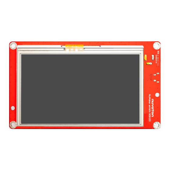
HMI hardware product quickly The following figures show the NuMaker-emWin-RDK-N9H20 demo board, in which the PCB integrated Nuvoton N9H20K51N 32-bit microcontroller with CPU core ARM926EJ-S, speed runs up at 192MHz, with 16KB I-cache, 16 KB D-cache and MMU, 8KB SRAM and 12KB IBR(Internal Boot ROM) for booting sources from USB ,SPI-NOR Flash or NAND Flash selectable. - Page 5 NuMaker-emWin-RDK-N9H20 ○ ○ DDR/Core Power 1.8V CPU RESET ○ ○ System Reset push buttom RTC battery ○ ○ LCD backlight driver Normal/recovery mode jumper ○ ○ NAND FLASH N9H20K51N ○ ○ LCD FC CON (RGB-24bits with TP) SPI-NOR FLASH ○ ○...
-
Page 6: System Circuitry Design Notes
NuMaker-emWin-RDK-N9H20 System Circuitry design notes 1.3.1 Main Clock The system clock circuit is formed by the feedback circuit inside the chip and the external 12MHz crystal oscillation circuit. Recommended crystal connection mode and device parameters as shown in the figure below. Note: The chosen capacitance needs to match the load capacitance of the crystal oscillator 1.3.2 RTC Clock... -
Page 7: Reset
NuMaker-emWin-RDK-N9H20 1.3.3 RESET The nRST signal of the N9H20K51N is the reset signal input pin, and the required reset effective signal is a low-level pulse. In order to stabilize the system robustness, it is recommended to use the following circuitry to implement reset signal. -
Page 8: Power Desing Notes
NuMaker-emWin-RDK-N9H20 NuMaker-emWin-RDK-N9H20 demo board power-on setting description Note USB Recovery mode Normal mode Note UART0 debug message output UART0 message disable DRAM type Part No. N9H20K31N SDRAM N9H20K11N DDR2 N9H20K51N LP-DDR Reserved PGC5 GPC4 NAND PAGE Size Auto by IBR 1.3.5 Power Desing Notes NuMaker-emWin-RDK-N9H20 demo board power supply design have the below considerations... - Page 9 NuMaker-emWin-RDK-N9H20 Note. Yellow line is I/O (3.3V) Blue line is core (1.8V) Purple line is nRST signal Mar. 26, 2021 Page 9 of 25 Rev 1.11...
-
Page 10: Pcb Layout Design Note
NuMaker-emWin-RDK-N9H20 PCB LAYOUT DESIGN NOTE. NuMaker-emWin-RDK-N9H20 demo board is a 2-layers PCB and single component side design, for getting good performance and system quality have some suggestions as the below please follow. USB differential Line have 3 conditions as far as possible: 1, equal length; 2, equal width and 3, Equidistant To do 90ohm ±10% impedance control. -
Page 11: Signal Integrity, Si
NuMaker-emWin-RDK-N9H20 Signal integrity, SI Due to 2- layers PCB does not have a separate GND plane, and to ensure the connectivity and integrity of the GND plane, the following requirements must be observed: The Bottom layer as far as possible or less device, to ensure the bottom surface of the GND integrity. -
Page 12: Power Supply And Power Filter Design Consideration
NuMaker-emWin-RDK-N9H20 Power supply and power filter design consideration 2.3.1 DDR MVDD & Core Power 1.8V Design About filter capacitance material and placement quantity Capacity material recommended to use X7R material, placing quantity suggest that the corresponding chip should have at least one 104pF capacitors at the each supply pin, and some special entrances suggest placing the 104 pF+10 uF combination. -
Page 13: I/O 3.3V Power Design
NuMaker-emWin-RDK-N9H20 2.3.2 I/O 3.3V Power Design About filter capacitance material and placement quantity Capacity material recommended to use X7R material, placing quantity suggest that the corresponding chip should have at least one 104pF capacitors at the each supply pin, and some special entrances suggest placing the 104 pF+10 uF combination. -
Page 14: Main Clock 12Mhz Design Suggestion
NuMaker-emWin-RDK-N9H20 Main Clock 12MHz Design Suggestion The 12MHz oscillator is the heart of the N9H20K51N chip and should be preferred in layout. Layout Basic principles: As close as possible to the chip pin, trace lines shoud be straight doesn’t be bent, and important thing is that XTAL part at the bottom has a complete GND plane. -
Page 15: Reset Layout Suggestion
NuMaker-emWin-RDK-N9H20 RESET Layout Suggestion For system ESD capability and stability, the RESET signal design and layout traces routing are worth a comprehensive consideration to do that best protection. Schematic details please refer to the schematic diagram of the NuMaker-emWin-RDK-N9H20, about the PCB layout was shown as below figure. -
Page 16: Numaker-Emwin-Rdk-N9H20 Demo Board Use Description
NuMaker-emWin-RDK-N9H20 NUMAKER-EMWIN-RDK-N9H20 DEMO BOARD USE DESCRIPTION The NuMaker-emWin-RDK-N9H20 demo board is powered by DC +5V and is accessed by the CON9 DC Power Jack. The demo board system block as the figure. System start up Mode switching by Normal/USB recovery mode jumper (i.e. Jumper Switch, R64 install or not) as the be low figure ... - Page 17 NuMaker-emWin-RDK-N9H20 Mar. 26, 2021 Page 17 of 25 Rev 1.11...
-
Page 18: Usb Port
NuMaker-emWin-RDK-N9H20 USB Port The USB interface on the board is mainly used for burning the update program, this interface does not have the power supply capability. When using, please choose to connect with this interface USB extension cable connected with the PC and then power supply through the system supply port.CON3 Communication Interface (UART0) uses TP16 (GPA10, URTX) &... -
Page 19: Test Report
NuMaker-emWin-RDK-N9H20 TEST REPORT Power consumption Condition : CPU@192MHz , emWin demo code is running Non-OS+emWin + 4.3 LCD:5V@335mA Non-OS+emWin without LCD: 5V@98mA ESD Test Report Contact (PCB GND & LCD metal ):+/- 4KV pass Air (LCD touch panel):+/- 8KV pass ... -
Page 20: Eft Test Result
NuMaker-emWin-RDK-N9H20 EFT Test Result EFT±4000V 5.0KHz pass EMI Test Result EN55032 Test Result : Pass Mar. 26, 2021 Page 20 of 25 Rev 1.11... - Page 21 NuMaker-emWin-RDK-N9H20 Mar. 26, 2021 Page 21 of 25 Rev 1.11...
-
Page 22: Numaker-Emwin-Rdk-N9H20 Demo Board Schematic
NuMaker-emWin-RDK-N9H20 NUMAKER-EMWIN-RDK-N9H20 DEMO BOARD SCHEMATIC N9H20 Schematic Mar. 26, 2021 Page 22 of 25 Rev 1.11... -
Page 23: Lcd Schematic
NuMaker-emWin-RDK-N9H20 LCD Schematic Mar. 26, 2021 Page 23 of 25 Rev 1.11... -
Page 24: Power Schematic
NuMaker-emWin-RDK-N9H20 Power Schematic Mar. 26, 2021 Page 24 of 25 Rev 1.11... -
Page 25: Revision History
Rename NuMaker-emWin-RDK-N9H20 Important Notice Nuvoton Products are neither intended nor warranted for usage in systems or equipment, any malfunction or failure of which may cause loss of human life, bodily injury or severe property damage. Such applications are deemed, “Insecure Usage”.
Need help?
Do you have a question about the ARM ARM926EL-S and is the answer not in the manual?
Questions and answers