Nuvoton NuMicro Series User Manual
1t 8051-based microcontroller
Hide thumbs
Also See for NuMicro Series:
- Technical reference manual (401 pages) ,
- User manual (53 pages) ,
- Quick start manual (15 pages)
Table of Contents
Advertisement
Quick Links
N76S003
NuMicro
®
Family
1T 8051-based Microcontroller
NuTiny-N76S003AT
User Manual
Evaluation Board for NuMicro
®
1T 8051 Series
The information described in this document is the exclusive intellectual property of
Nuvoton Technology Corporation and shall not be reproduced without permission from Nuvoton.
Nuvoton is providing this document only for reference purposes of NuMicro microcontroller based system
design. Nuvoton assumes no responsibility for errors or omissions.
All data and specifications are subject to change without notice.
For additional information or questions, please contact: Nuvoton Technology Corporation.
www.nuvoton.com
Nov. 15, 2023
Page 1 of 24
Rev 1.00
Advertisement
Table of Contents

Related Manuals for Nuvoton NuMicro Series


Summary of Contents for Nuvoton NuMicro Series
- Page 1 The information described in this document is the exclusive intellectual property of Nuvoton Technology Corporation and shall not be reproduced without permission from Nuvoton. Nuvoton is providing this document only for reference purposes of NuMicro microcontroller based system design. Nuvoton assumes no responsibility for errors or omissions.
-
Page 2: Table Of Contents
3.3.8 Pin Assignment for Extended Connector ................8 QUICK START ....................10 Toolchains Supporting ................... 10 Nuvoton Nu-Link Driver Installation ................ 10 BSP Firmware Download ..................12 Hardware Setup ..................... 12 Find the Example Project ..................13 Execute the Project under Toolchains ..............14 4.6.1... - Page 3 N76S003 List of Figure Figure 3.1-1 NuTiny-N76S003AT (PCB Board) ....................7 Figure 4.2-1 Nu-Link USB Driver Installation Setup ................... 10 Figure 4.2-2 Nu-Link USB Driver Installation ..................... 11 Figure 4.4-1 Open VCOM Function ........................12 Figure 4.4-2 ICE USB Connector ........................12 Figure 4.4-3 Device Manger ..........................
- Page 4 N76S003 List of Table Table 3.3-1 Voltage connector ..........................8 Table 3.3-2 Nu-Link-Me virtual COM port ......................8 Table 3.3-3 Pin Assignment for N76S003AT20 ....................9 Nov. 15, 2023 Page 4 of 24 Rev 1.00...
-
Page 5: Overview
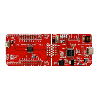
N76S003 OVERVIEW The NuTiny-N76S003AT is an evaluation board for Nuvoton NuMicro N76S003AT20 microcontrollers. The NuTiny-N76S003AT consists of two parts: an N76S003 target board and an on-board Nu-Link2- Me debugger and programmer. The NuTiny-N76S003AT is designed for project evaluation, prototype development and validation with power consumption monitoring function. The NuTiny-N76S003AT board is suitable for a wide range of applications such as home appliances, LED lighting controls, motor controls or Industrial automation. -
Page 6: Features
N76S003 FEATURES ⚫ NuMicro N76S003AT20 used as main microcontroller ⚫ N76S003AT20 full pins extension connectors ⚫ Flexible board power supply: External V power connector – ICE USB connector on Nu-Link2-Me – ⚫ On-board Nu-Link2-Me debugger and programmer: Debug through OCD interface –... -
Page 7: Hardware Configuration
To use Nu-Link-Me Debug adaptor with Keil, please refer to “Nuvoton Nu-Link debug adapter user manual” in detail. This document will be stored in the local hard disk when user installs each driver. Nu-Link-Me also supports virtual COM port function. User can use Nu-Link-Me as a USB to UART virtual COM port, which connects to on-board N76S003 AT20 UART0. -
Page 8: Nutiny-N76S003At Power Setting And Connector
JP9 input Table 3.3-1 Voltage connector 3.3.2 Debug Connector ⚫ JP4: Connector in target board (NuTiny-N76S003AT ) for connecting with Nuvoton ICE adaptor (Nu-Link-Me) ⚫ JP2: Connector in ICE adaptor (Nu-Link-Me) for connecting with a target board (for example NuTiny-N76S003AT ) 3.3.3... - Page 9 N76S003 20 pin. Table 3.3-3 is the pin assignment for N76S003AT20. Pin No Pin Function Pin No Pin Function PWM2/IC6/T0/AIN4/P0.5 P1.4/SDA/FB/PWM1 TXD/AIN3/P0.6 P1.3/SCL/[STADC] RXD/AIN2/P0.7 P1.2/PWM0/IC0 RST/P2.0 P1.1/PWM1/IC1/AIN7/CLO INT0/OSCIN/AIN1/P3.0 P1.0/PWM2/IC2/SPCLK INT1/AIN0/P1.7 P0.0/PWM3/IC3/MOSI/T1 P0.1/PWM4/IC4/MISO [SDA]/TXD_1/ICPDA/OCDDA/P1.6 P0.2/ICPCK/OCDCK/RXD_1/[SCL] P0.3/PWM5/IC5/AIN6 PWM5/IC7/SS/P1.5 P0.4/AIN5/STADC/PWM3/IC3 Table 3.3-3 Pin Assignment for N76S003AT20 Nov.
-
Page 10: Quick Start
IAR EMBEDDED WORKBENCH FOR 8051 ⚫ NuEclipse_Windows (For NuMicro 8051) ⚫ NuEclipse_Linux (For NuMicro 8051) Nuvoton Nu-Link Driver Installation Download and install the latest Nuvoton Nu-Link Driver. ⚫ Download and install Nu-Link_Keil_Driver when using Keil MDK. ⚫ Download and install Nu-Link_IAR_Driver when using IAR EWARM. -
Page 11: Figure 4.2-2 Nu-Link Usb Driver Installation
N76S003 Figure 4.2-2 Nu-Link USB Driver Installation Nov. 15, 2023 Page 11 of 24 Rev 1.00... -
Page 12: Bsp Firmware Download
N76S003 BSP Firmware Download Download and unzip the Board Support Package (BSP). Hardware Setup 1. Open the virtual COM (VCOM) function by changing Nu-Link2-Me VCOM Switch No. 1 and 2 to ON. Figure 4.4-1 Open VCOM Function 2. Connect the ICE USB connector shown in Figure 4.4-2 to the PC USB port through a USB cable. -
Page 13: Find The Example Project
N76S003 3. Find the “Nuvoton Virtual COM Port” on the Device Manger as Figure 4.4-3. Figure 4.4-3 Device Manger 4. Open a serial port terminal, PuTTY for example, to print out debug message. Set the speed to 115200. Figure 4.4-4 presents the PuTTY session setting. -
Page 14: Execute The Project Under Toolchains
N76S003 Template KEIL NuEclipse Figure 4.5-1 Template Project Folder Path Execute the Project under Toolchains Open and execute the project under the toolchain. The section 4.6.1 and 4.6.2 describe the steps of executing project in Keil MDK and IAR EWARM, respectively. 4.6.1 Keil MDK This section provides steps to beginners on how to run a project by using Keil MDK. -
Page 15: Figure 4.6-2 Project File Migrate To Version 5 Format
N76S003 Figure 4.6-2 Project File Migrate to Version 5 Format 6. Make sure the debugger is “Nuvoton Nu-Link Debugger” as shown in Figure 4.6-3 and Figure 4.6-4. Figure 4.6-3 Debugger Setting in Options Window Note: If the dropdown menu in Figure 4.6-3 does not contain “Nuvoton Nu-Link Debugger” item, please rework section. -
Page 16: Figure 4.6-4 Programming Setting In Options Window
N76S003 Figure 4.6-4 Programming Setting in Options Window 7. Rebuild all target files. After successfully compiling the project, download code to the Flash memory. Click “Start/Stop Debug Section” button to enter debug mode. 1. Rebuild 2. Successfully compile 3. Download 4. -
Page 17: Figure 4.6-6 Keil Mdk Debug Mode
N76S003 be printed out as shown in Figure 4.6-7. User can debug the project under debug mode by checking source code, assembly language, peripherals’ registers, and setting breakpoint, step run, value monitor, etc. 3 1 2 1. Run 2. Stop 3. -
Page 18: Iar Ewarm
N76S003 4.6.2 IAR EWARM This section provides steps to beginners on how to run a project by using IAR EWARM. 9. Double click the “Template.eww” to open the project. 10. Make sure the toolbar contains “Nu-Link” item as shown in Figure 4.6-8. Note: If the toolbar does not contain “Nu-Link”... -
Page 19: Figure 4.6-10 Iar Ewarm Debug Mode
N76S003 12. Figure 4.6-10 shows the debug mode under IAR EWARN. Click “Go” and the debug message will be printed out as shown in Figure 4.6-11. User can debug the project under debug mode by checking source code, assembly language, peripherals’ registers, and setting breakpoint, step run, value monitor, etc. -
Page 20: Nutiny-N76S003At Schematics
N76S003 NUTINY-N76S003AT SCHEMATICS Nu-Link2-Me Figure 5.1-1 shows the Nu-Link2-Me circuit. ICE CONNECT IF USBVBUS ICE1 SHIELD ICELED USB_D- SHIELD USB_D+ SHIELD ICP1 SHIELD ISPLED Y ELLOW VCC_connect IDLE1 mini USB 5pin 8P4R-330 VCC_connect ICEDAT TICEDAT ICE_USB ICECLK FERRITE BEAD TICECLK BUSY 1 ICERST TICERST... -
Page 21: Nutiny-N76S003At Schematics
N76S003 NuTiny-N76S003AT Schematics Figure 5.2-1 shows the N76S003AT20 target board circuit. Off-page Connector P[1:20] JP10 P[1:20] TICERST 10uF/10V 0.1u TICEDAT TICEDAT PUSH BOTTOM (B) TICECLK TICECLK TICERST SIP-2P SIP-2P TICERST Tiny _TX 10uF/10V Tiny _TX Reset Power Tiny _RX Tiny _RX P0.5/AIN4/T0/IC6/PWM2 IC3/PWM3/STADC/AIN5/P0.4 Tiny _TX... -
Page 22: Figure 5.3-2 Rear Placement
N76S003 Figure 5.3-2 Rear Placement Nov. 15, 2023 Page 22 of 24 Rev 1.00... -
Page 23: Revision History
N76S003 REVISION HISTORY Date Revision Description 2023.11.15 1.00 Initial Release Nov. 15, 2023 Page 23 of 24 Rev 1.00... - Page 24 N76S003 Important Notice Nuvoton Products are neither intended nor warranted for usage in systems or equipment, any malfunction or failure of which may cause loss of human life, bodily injury or severe property damage. Such applications are deemed, “Insecure Usage”.
Need help?
Do you have a question about the NuMicro Series and is the answer not in the manual?
Questions and answers