Table of Contents
Advertisement
Quick Links
MuMaker-PFM-M487KM
®
®
ARM
Cortex
- M
32-bit Microcontroller
NuMaker-PFM-M487KM
User Manual
®
NuMicro
M480 Series
The information described in this document is the exclusive intellectual property of
Nuvoton Technology Corporation and shall not be reproduced without permission from Nuvoton.
Nuvoton is providing this document only for reference purposes of NuMicro microcontroller based system
design. Nuvoton assumes no responsibility for errors or omissions.
All data and specifications are subject to change without notice.
For additional information or questions, please contact: Nuvoton Technology Corporation.
www.nuvoton.com
APR
30, 2020
Page 1 of 44
Rev 1.00
Advertisement
Table of Contents

Related Manuals for Nuvoton NuMicro M480 Series


Summary of Contents for Nuvoton NuMicro M480 Series
- Page 1 The information described in this document is the exclusive intellectual property of Nuvoton Technology Corporation and shall not be reproduced without permission from Nuvoton. Nuvoton is providing this document only for reference purposes of NuMicro microcontroller based system design. Nuvoton assumes no responsibility for errors or omissions.
-
Page 2: Table Of Contents
Nu-Link2-Me ................... 22 PCB Placement ..................23 Quick Start ..................24 Toolchains Supporting ................24 Nuvoton Nu-Link Driver Installation ..............24 BSP Firmware Download ................26 Hardware Setup ..................26 Find the Example Project ................28 Execute the Project under Toolchains ............. 28 Keil MDK ....................... - Page 3 MuMaker-PFM-M487KM IAR EWARM ....................32 3.6.2 NuEclipse ...................... 33 3.6.3 NuMaker-PFM-M487KM Schematics ............34 Nu-Link2-Me ................... 34 M487KMCAN ..................35 Power Supply ..................36 Arduino UNO Compatible Interface ..............37 MicroSD Card ..................38 USB 2.0 HS OTG and USB 1.1 FS OTG ............39 Ethernet ....................
- Page 4 MuMaker-PFM-M487KM List of Figures Figure 1-1 NuMaker-PFM-M487KM Board ..................6 Figure 2-1 Front View of NuMaker-PFM-M487KM Board ..............8 Figure 2-2 Rear View of NuMaker-PFM-M487KM Board ..............9 Figure 2-3 Arduino UNO Compatible Interface ................10 Figure 2-4 NuMaker-PFM-M487KMCAN Extended Connectors ........... 12 Figure 2-5 3.5mm Phone Jack Diagram ..................
- Page 5 MuMaker-PFM-M487KM List of Tables Table 2-1 Arduino UNO Interface Mapping with M487KMCAN GPIO ........... 11 Table 2-2 Extended Connector JP6 Interface with M487KMCAN GPIO ........13 Table 2-3 Extended Connector JP8 Interface with M487KMCAN GPIO ........14 Table 2-4 Extended Connector JP7 Interface with M487KMCAN GPIO ........15 Table 2-5 Extended Connector JP9 Interface with M487KMCAN GPIO ........
-
Page 6: Overview
MuMaker-PFM-M487KM OVERVIEW This user manual is aimed to give users a fast introduction to the use of NuMaker-PFM-M487KM board. The NuMaker-PFM-M487KM consists of two parts, a M487KM platform and an on-board Nu-Link2-Me debugger and programmer. The NuMaker-PFM-M487KM allows users to quickly develop and easily program and debug application. -
Page 7: Numaker-Pfm-M487Km Board Features
MuMaker-PFM-M487KM Quadrature Encoder Interface (QEI) WDT and WWDT UART Smart Card (ISO-7816-3) Host Interface SPIM Universal Serial Control Interface (USCI) USB 2.0 High-Speed OTG / Host / Device USB 1.1 Full-Speed OTG / Host / Device ... -
Page 8: Numaker-Pfm-M487Km Board Overview
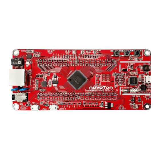
MuMaker-PFM-M487KM NUMAKER-PFM-M487KM BOARD OVERVIEW Front View Figure 2-1 shows the main components and connectors from the front side of NuMaker-PFM-M487KM board. The following lists components and connectors from the front view: Target Chip: M487KMCAN (U1) Audio: Audio Codec NAU88L25 (U8), Headphone (CN2) ... -
Page 9: Rear View
MuMaker-PFM-M487KM Rear View Figure 2-2 shows the main components and connectors from the rear side of NuMaker-PFM-M487KM board. The following lists components and connectors from the rear view: MicroSD Card Slot: T-Flash slot (U9) Nu-Link2-Me MCUVCC Power Switch (ICEJPR1) ... -
Page 10: Arduino Uno Compatible Interface
MuMaker-PFM-M487KM Arduino UNO Compatible Interface Figure 2-3 shows the Arduino UNO compatible interface. Figure 2-3 Arduino UNO Compatible Interface 30, 2020 Page 10 of 44 Rev 1.00... -
Page 11: Table 2-1 Arduino Uno Interface Mapping With M487Kmcan Gpio
MuMaker-PFM-M487KM Table 2-1 Arduino UNO Interface Mapping with M487KMCAN GPIO NuMaker-PFM-M487KM NuMaker-PFM-M487KM Header Header Compatible to Compatible to GPIO Pin of M487 GPIO Pin of M487 Arduino UNO Arduino UNO NU1.1 NU4.10 PC.5 NU1.2 IOREF NU4.9 PC.4 NU1.3 RESET RESET NU4.8 VREF NU1.4... -
Page 12: Pin Assignment For Extended Connectors
MuMaker-PFM-M487KM Pin Assignment for Extended Connectors The NuMaker-PFM-M487KM provides the M487KMCAN target chip onboard and extended connectors (JP6, JP7, JP8 and JP9) for LQFP128-pin. The Figure 2-4 shows the NuMaker-PFM- M487KMCAN extended connectors. Figure 2-4 NuMaker-PFM-M487KMCAN Extended Connectors 30, 2020 Page 12 of 44 Rev 1.00... -
Page 13: Table 2-2 Extended Connector Jp6 Interface With M487Kmcan Gpio
MuMaker-PFM-M487KM Table 2-2 Extended Connector JP6 Interface with M487KMCAN GPIO NuMaker-PFM-M487KM NuMaker-PFM-M487KM Header Header Pin No. Function Pin No Function JP6.1 PB.5 JP6.2 PB.4 JP6.3 PB.3 JP6.4 OPA0_O JP6.5 PC.12 JP6.6 PC.11 JP6.7 PC.10 JP6.8 PC.9 JP6.9 OPA0_N JP6.10 OPA0_P JP6.11 JP6.12 3VCC... -
Page 14: Table 2-3 Extended Connector Jp8 Interface With M487Kmcan Gpio
MuMaker-PFM-M487KM Table 2-3 Extended Connector JP8 Interface with M487KMCAN GPIO NuMaker-PFM-M487KM NuMaker-PFM-M487KM Header Header Pin No. Function Pin No Function JP7.1 LED_R JP7.2 LED_G JP7.3 PH.6 JP7.4 PH.7 JP7.5 XT1_IN JP7.6 XT1_OUT JP7.7 JP7.8 3VCC JP7.9 EMAC_MDC JP7.10 EMAC_MDIO JP7.11 EMAC_TXD0 JP7.12 EMAC_TXD1... -
Page 15: Table 2-4 Extended Connector Jp7 Interface With M487Kmcan Gpio
MuMaker-PFM-M487KM Table 2-4 Extended Connector JP7 Interface with M487KMCAN GPIO NuMaker-PFM-M487KM NuMaker-PFM-M487KM Header Header Pin No. Function Pin No Function JP8.1 ICEDAT JP8.2 ICECLK JP8.3 I2C2_SCL JP8.4 I2C2_SDA JP8.5 I2C1_SCL JP8.6 I2C1_SDA JP8.7 PC.3 JP8.8 PC.2 JP8.9 PC.1 JP8.10 PC.0 JP8.11 JP8.12 3VCC... -
Page 16: Table 2-5 Extended Connector Jp9 Interface With M487Kmcan Gpio
MuMaker-PFM-M487KM Table 2-5 Extended Connector JP9 Interface with M487KMCAN GPIO NuMaker-PFM-M487KM NuMaker-PFM-M487KM Header Header Pin No. Pin Name Pin No Pin Name JP9.1 JP9.2 JP9.3 PE.5 JP9.4 JP9.5 PE.3 JP9.6 JP9.7 JP9.8 3VCC JP9.9 PE.1 JP9.10 PE.0 JP9.11 PH.8 JP9.12 PH.9 JP9.13 PH.10... -
Page 17: System Configuration
MuMaker-PFM-M487KM System Configuration 2.5.1 5V Power Source ICEJ: USB connector in Nu-Link-Me to program code and supplies 5V power from PC Host. CON1: USB 2.0 High-Speed OTG connector on NuMaker-PFM-M487KM board to supply 5V power from PC Host when this USB is a device that be decided by the ID pin of OTG cable and this ID pin is low. -
Page 18: Usb Connectors
MuMaker-PFM-M487KM 2.5.3 USB Connectors ICEJ3: USB connector (ICE) in Nu-Link-Me that connects to a PC’s USB Host port to program code and supply power. CON1: USB 2.0 High-Speed connector (OTG) on NuMaker-PFM-M487KM board for USB OTG application use. ... -
Page 19: Audio
MuMaker-PFM-M487KM Audio NuMaker-PFM-M487KM features a Nuvoton NAU88L25 audio codec which is an ultra-low power high performance audio codec designed for headphone or headset application. It includes one I2S/PCM interface, one high quality stereo DACs, one mono ADC, a Class G stereo headphone amplifier, and industry leading advanced headset features. -
Page 20: Heartbeat Sensor
MuMaker-PFM-M487KM Heartbeat Sensor NuMaker-PFM-M487KM features an on-board heartbeat sensor, it can detect the tiny electrical signal between human’s right and left hand during each heartbeat. The tiny electrical signal passes through three stages of operational amplifiers which are built in M487KMCAN to amplify the differential electrical signal and filter the noise of environment. -
Page 21: Table 2-7 Pin Usage Of Heartbeat Sensor
MuMaker-PFM-M487KM The pins of heartbeat sensor are share with other function of NuMaker-PFM-M487KM, the Table 2-7 shows the usage of heartbeat sensor. Table 2-7 Pin Usage of Heartbeat Sensor Heartbeat Alternative M487JIDAE Comment Sensor Function Short R69 to use the heartbeat function, otherwise it will be D0 of UNO PB.2 OPA0_O Interface. -
Page 22: Nu-Link2-Me
MuMaker-PFM-M487KM Nu-Link2-Me The Nu-Link2-Me is a debugger and programmer that supports on-line programming and debugging through SWD interface. The on-board 16 Mbit SPI Flash allows it to off-line program the target microcontroller. Additionally, the Nu-Link2-Me provides virtual COM port (VCOM) function to print out messages on PC. -
Page 23: Pcb Placement
MuMaker-PFM-M487KM PCB Placement Figure 2-7 and Figure 2-8 show the front and rear placement of NuMaker-PFM-M487KM board. Figure 2-7 Front Placement Figure 2-8 Rear Placement 30, 2020 Page 23 of 44 Rev 1.00... -
Page 24: Quick Start
KEIL MDK Nuvoton edition M0/M23 IAR EWARM NuEclipse (GCC)(Windows) NuEclipse (GCC)(Linux) Nuvoton Nu-Link Driver Installation Download and install the latest Nuvoton Nu-Link Driver. Download and install Nu-Link_Keil_Driver when using Keil MDK. Download and install Nu-Link_IAR_Driver when using IAR EWARM. -
Page 25: Figure 3-2 Nu-Link Usb Driver Installation
MuMaker-PFM-M487KM Figure 3-2 Nu-Link USB Driver Installation 30, 2020 Page 25 of 44 Rev 1.00... -
Page 26: Bsp Firmware Download
2. Connect the ICE USB connector shown in Figure 3-4 to the PC USB port through USB cable. Figure 3-4 ICE USB Connector 3. Find the “Nuvoton Virtual COM Port” on the Device Manger as Figure 3-5. 30, 2020 Page 26 of 44... -
Page 27: Figure 3-5 Device Manger
MuMaker-PFM-M487KM Figure 3-5 Device Manger 4. Open a serial port terminal, PuTTY for example, to print out debug message. Set the speed to 115200. Figure 3-6 presents the PuTTY session setting. Figure 3-6 PuTTY Session Setting 30, 2020 Page 27 of 44 Rev 1.00... -
Page 28: Find The Example Project
MuMaker-PFM-M487KM Find the Example Project Use the “Template” project as an example. The project can be found under the BSP folder as shown in Figure 3-7. M480_Series_BSP_CMSIS_V3.XX.XXX SampleCode Template Keil Figure 3-7 Template Project Folder Path Execute the Project under Toolchains Open and execute the project under the toolchain. -
Page 29: Figure 3-9 Project File Migrate To Version 5 Format
Figure 3-9 Project File Migrate to Version 5 Format 2. Make sure the debugger is “Nuvoton Nu-Link Debugger” as shown in Figure 3-10 and Figure 3-11. Note: If the dropdown menu in Figure 3-10 does not contain “Nuvoton Nu-Link Debugger” item, please rework section 3.2. -
Page 30: Figure 3-11 Programming Setting In Options Window
MuMaker-PFM-M487KM Figure 3-11 Programming Setting in Options Window 3. Rebuild all target files. After successfully compile the project, download code to the flash memory. Click “Start/Stop Debug Section” button can enter debug mode. 1. Rebuild 2. Successfully compile 3. Download 4. -
Page 31: Figure 3-13 Keil Mdk Debug Mode
MuMaker-PFM-M487KM source code, assembly language, peripherals’ registers, and setting breakpoint, step run, value monitor, etc. 3 1 2 1. Run 2. Stop 3. Reset Figure 3-13 Keil MDK Debug Mode Figure 3-14 Debug Message on Serial Port Terminal Windows 30, 2020 Page 31 of 44 Rev 1.00... -
Page 32: Iar Ewarm
MuMaker-PFM-M487KM 3.6.2 IAR EWARM This section provides steps to beginners on how to run a project by using IAR EWARM. 1. Double click the “Template.eww” to open the project. 2. Make sure the toolbar contain “Nu-Link” item as shown in Figure 3-15. Note: If the toolbar does not contain “Nu-Link”... -
Page 33: Nueclipse
MuMaker-PFM-M487KM 4. Figure 3-17 shows the debug mode under IAR EWARN. Click “Go” and the debug message will be printed out as shown in Figure 3-18. User can debug the project under debug mode by checking source code, assembly language, peripherals’ registers, and setting breakpoint, step run, value monitor, etc. -
Page 34: Numaker-Pfm-M487Km Schematics
MuMaker-PFM-M487KM NUMAKER-PFM-M487KM SCHEMATICS Nu-Link2-Me Figure 4-1 shows the Nu-Link2-Me circuit. The Nu-Link2-Me is a debugger and programmer that supports on-line programming and debugging through SWD interface. Figure 4-1 Nu-Link2-Me Circuit 30, 2020 Page 34 of 44 Rev 1.00... -
Page 35: M487Kmcan
MuMaker-PFM-M487KM M487KMCAN Figure 4-2 shows the pin assignment of the M487KMCAN. Figure 4-2 M487KMCAN Pin Assignment 30, 2020 Page 35 of 44 Rev 1.00... -
Page 36: Power Supply
MuMaker-PFM-M487KM Power Supply Figure 4-3 shows power configurations of NuMaker-PFM-M487KM board. Figure 4-3 Power Circuit and Configurations 30, 2020 Page 36 of 44 Rev 1.00... -
Page 37: Arduino Uno Compatible Interface
MuMaker-PFM-M487KM Arduino UNO Compatible Interface Figure 4-4 shows the Arduino UNO compatible interface of NU1, NU2, NU5, NU6 and NU7 connectors. Figure 4-4 Arduino UNO Compatible Interface 30, 2020 Page 37 of 44 Rev 1.00... -
Page 38: Microsd Card
MuMaker-PFM-M487KM MicroSD Card Figure 4-5 shows the MicroSD Card circuit on the NuMaker-PFM-M487KM board. Figure 4-5 MicroSD Card Circuit 30, 2020 Page 38 of 44 Rev 1.00... -
Page 39: Usb 2.0 Hs Otg And Usb 1.1 Fs Otg
MuMaker-PFM-M487KM USB 2.0 HS OTG and USB 1.1 FS OTG Figure 4-6 shows the USB 2.0 HS OTG and USB 1.1 FS OTG circuits on the NuMaker-PFM-M487KM board. Figure 4-6 USB HS OTG and FS OTG Circuits 30, 2020 Page 39 of 44 Rev 1.00... -
Page 40: Ethernet
MuMaker-PFM-M487KM Ethernet Figure 4-7 shows the Ethernet interface for networking application on the NuMaker-PFM-M487KM board. Figure 4-7 Ethernet Circuit 30, 2020 Page 40 of 44 Rev 1.00... -
Page 41: 24-Bit Stereo Audio Codec
MuMaker-PFM-M487KM 24-bit Stereo Audio Codec Figure 4-8 shows the audio codec application circuit based on NAU88L25 to simplify implementation of complete audio system solutions. Figure 4-8 Audio Codec Circuit 30, 2020 Page 41 of 44 Rev 1.00... -
Page 42: Heartbeat Sensor
MuMaker-PFM-M487KM Heartbeat Sensor Figure 4-9 shows the heartbeat sensor application circuit on the NuMaker-PFM-M487KM board. Figure 4-9 Heartbeat Sensor Circuits 30, 2020 Page 42 of 44 Rev 1.00... -
Page 43: Revision History
MuMaker-PFM-M487KM REVISION HISTORY Date Revision Description 2020.04.30 1.00 Initially issued. 30, 2020 Page 43 of 44 Rev 1.00... - Page 44 MuMaker-PFM-M487KM Important Notice Nuvoton Products are neither intended nor warranted for usage in systems or equipment, any malfunction or failure of which may cause loss of human life, bodily injury or severe property damage. Such applications are deemed, “Insecure Usage”.
Need help?
Do you have a question about the NuMicro M480 Series and is the answer not in the manual?
Questions and answers