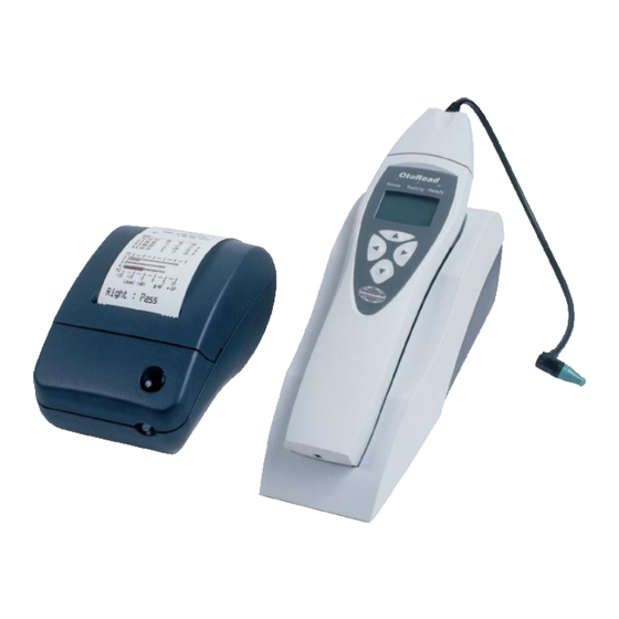
Interacoustics OtoRead Instructions For Use Manual
Hide thumbs
Also See for OtoRead:
- Instructions for use manual (172 pages) ,
- Operation manual (58 pages) ,
- Instructions for use manual (79 pages)
Summary of Contents for Interacoustics OtoRead
- Page 1 D-0004822-C – 2019/03 Science made smarter Instructions for Use - EN OtoRead Module...
-
Page 2: Table Of Contents
How to find the COM port on the PC (Windows 10)? ............13 ® Setting up the COM port ....................... 14 The OtoRead™ device switches off by itself too quickly ............15 Why does the “Testing” LED flash when the device is in the cradle? ........15... -
Page 3: Introduction
Audiometer Allé 1 5500 Middelfart Denmark This manual describes the functions of the OtoRead Module software. It is recommended that users of the software read the manual thoroughly before using it. 1.2 General The OtoRead™ module is used to save and view measurements recorded using the OtoRead device. -
Page 4: Installation And Setup
Minimum display of 1280 x 768 • One or more USB ports, version 1.1 or higher • 2.2 Operating system compatibility The OtoRead Module software is compatible with the following operating systems: Windows 10 32-bit and 64-bit • ® Windows 8.1 32-bit and 64-bit... -
Page 5: Connecting Otoread Tm To The Pc
2.6 Connecting OtoRead to the PC The OtoRead™ can be connected to the PC using an RS232 serial cable or using a USB-to-serial converter cable. OtoRead™ with RS232 serial cable OtoRead™ with USB-to-serial converter cable Important: Install the USB-to-serial driver before connecting the USB-to-serial cable to the PC. - Page 6 8. Click on Create. 9. Click on Apply Settings. 10. Click on OK. 11. The OtoRead Module is now available from the Select Instrument list. 12. Double click on OtoRead Module in the instrument list. 13. Click on Settings and select Options.
-
Page 7: Configuring Otoread™ Module To Work With Otoaccess ® 2.X Or Higher
2.x uses serial port COM1 as a default for the communication between the OtoRead™ ® device and OtoRead™ Module. The serial port must be set to COM1 in the PC’s Device Manager for a connection to be established. Refer to section 4 (Troubleshooting & FAQs) for further information about finding or changing the COM port settings on your PC. - Page 8 Select Serial under Device Communication. This applies even if the OtoRead device is connected using a USB-to-serial cable ® Now OtoAccess and the OtoRead™ Module are ready to retrieve data from the OtoRead™. D-0115350-B – 2019/04 Page 6 OtoRead™ Module - Instructions for Use - EN...
-
Page 9: Using The Otoread Tm Module Software
3 Using the OtoRead Module software 3.1 Main window The figure below shows the main window of the OtoRead™ Module software. Each major section of this window is described below. Menus. Shortcut icons. Patient details including name, date of birth, patient ID and gender. -
Page 10: Menus
Type of charts • • Language Address for the printout • Help About Interacoustics Displays the version number of OtoRead Module… OtoRead™ Module Help Opens a help manual D-0115350-B – 2019/04 Page 8 OtoRead™ Module - Instructions for Use - EN... -
Page 11: Toolbar/Shortcut Icons
NOTE: The OtoRead™ can be configured to store two tests (a test for the right ear and the left ear) or up to 250 tests. All of the tests stored in the OtoRead™ will download using this procedure. See your OtoRead™ Instructions for Use for more information about test storage. -
Page 12: Interpreting Results
The number at the top of each bar is the SNR (SNR = OAE level minus the NF) The green line displays the waveform reproducibility as a percentage • D-0115350-B – 2019/04 Page 10 OtoRead™ Module - Instructions for Use - EN... - Page 13 The white/grey squares in the graph indicate the noise floor (NF) • The number displayed for each frequency is the SNR (SNR = OAE level minus the NF) D-0115350-B – 2019/04 Page 11 OtoRead™ Module - Instructions for Use - EN...
-
Page 14: Printing The Results
3.6 Printing the results There are two ways to print measurements from the OtoRead™ Module. Go to File – Print. Click on the Print Current Record icon. A single measurement or two measurements (one for right and left ear) can be printed on one page. -
Page 15: Troubleshooting & Faqs
In this example, the OtoRead is connected In this example, the OtoRead is connected using a USB-to-serial converter cable on COM1. using an RS232 serial cable on COM2. D-0115350-B – 2019/04 Page 13 OtoRead™ Module - Instructions for Use - EN... -
Page 16: Setting Up The Com Port
6. Change the COM Port Number if needed (e.g., if using OtoAccess® 2.x, the COM port must be set to COM1). 7. Set the Driver Buffer Size (or Received and Transmit) to 4096. 8. Click OK and exit. The Port settings are now set. D-0115350-B – 2019/04 Page 14 OtoRead™ Module - Instructions for Use - EN... -
Page 17: The Otoread™ Device Switches Off By Itself Too Quickly
4.4 Why does the “Testing” LED flash when the device is in the cradle? When the OtoRead™ device is turned on and placed in the cradle with a connection to a PC, the “Ready” LED will be green and the “Testing” LED will flash orange to indicate it ready for PC use. “Waiting on PC”...


Need help?
Do you have a question about the OtoRead and is the answer not in the manual?
Questions and answers