
Related Manuals for Interacoustics Orion


Summary of Contents for Interacoustics Orion
- Page 1 Science made smarter Installation Instructions Orion Rotary Chair (Auto- Traverse/Comprehensive) Micromedical by Interacoustics...
- Page 3 All rights reserved. Information in this document is proprietary to Interacoustics⅍. The information in this document is subject to change without notice. No part of this document may be reproduced or transmitted in any form or by any means without a prior written permission of Interacoustics⅍.
-
Page 4: Table Of Contents
Table of Contents INTRODUCTION ........................... 1 About this manual ........................ 1 Environmental Conditions ....................1 Marking ..........................1 Required tools ........................3 Determine location for booth and chair installation ............. 6 UNPACKING AND INSPECTION ....................7 Inspection of shipment ......................7 Unpacking the booth ...................... -
Page 6: Introduction
Introduction About this manual his manual detail the installation procedure for the Orion Chair (Auto-transverse / Comprehensive), used with the VisualEyes™ 515 and VisualEyes™ 525 Software version 3.0 and later. Both Auto-transverse and Comprehensive will be hereafter denoted by ‘Orion Chair’ if it is not specified. - Page 7 Chinese RoHS compliance standard where the product contains less than the maximum concentration value of lead, mercury, cadmium, hexavalent chromium, polybrominated biphenyls, and polybrominated diphenyl ethers. This product contains a component (Orion Comprehensive/Auto Traverse chair) of ‘Class 2 Laser beam’. Hence, do not look directly...
-
Page 8: Required Tools
Required tools The following tools are required to assemble the Orion Chair which will be provided by the dealer. NOTICE It is important to note that two people are required for this installation process. The installation process approximately will take 5 to 6 hours to complete. - Page 9 Small battery powered screwdrivers (flat blade) Small head Phillips screwdriver (supplied with the product) 16 oz hammer Small Shop-Vac (Vacuum cleaner with hose adapter) D-0120794-C – 2019/11 Orion Rotary Chair Installation Instructions Page 4...
- Page 10 Rubber head mallet Paper towels and water for concrete dust cleanup Bubble level, 1’-3’ Bubble level or smartphone level Pencil with eraser, Knife and Scissors Stud finder Compressed air D-0120794-C – 2019/11 Orion Rotary Chair Installation Instructions Page 5...
-
Page 11: Determine Location For Booth And Chair Installation
Ensure that you have a very clear floor plan to install the booth with the chair and other accessories. Ensure that the room has at least an 8 ft high ceiling and space in front of the booth to lift the round roof into place. D-0120794-C – 2019/11 Orion Rotary Chair Installation Instructions Page 6... -
Page 12: Unpacking And Inspection
The Door Panel can come open and break, so carry the door in a way it doesn’t open. If a cart is used for transporting panels, make sure the panels are protected by pads. D-0120794-C – 2019/11 Orion Rotary Chair Installation Instructions Page 7... -
Page 13: Unpacking Chair From The Crate
While the chair weight is counterbalanced by the person handling the hand truck, the second person can help to guide, move and lower the chair in position. D-0120794-C – 2019/11 Orion Rotary Chair Installation Instructions Page 8... -
Page 14: Booth Installation
Press down on the flooring by walking on the flooring over the tape. Repeat the same steps to place another vinyl flooring to cover another half of booth flooring. D-0120794-C – 2019/11 Orion Rotary Chair Installation Instructions Page 9... -
Page 15: Booth Wall Assembly
Insert one of the marked wall screws into existing screw hole in top at 45 degree angle and the panel levels can be adjusted using shims (Figure 4 and Figure 5) D-0120794-C – 2019/11 Orion Rotary Chair Installation Instructions Page 10... - Page 16 Place a curved threshold strip under the door, use multiple threshold strip if necessary to keep the threshold in place with friction. This threshold strip protects the narrow door frame from cracking when stepped on. D-0120794-C – 2019/11 Orion Rotary Chair Installation Instructions Page 11...
-
Page 17: Booth Ceiling Assembly
Using two people, walk the assembled booth ceiling above the booth and lower it into place. Do not lift the ceiling by the wings to prevent damage to the ceiling. Caution must be taken not to damage the two wires that located on top of the booth door. D-0120794-C – 2019/11 Orion Rotary Chair Installation Instructions Page 12... - Page 18 Caution: Be careful not to crush the intercom connection wire and booth door safety switch wire when setting the ceiling in place. Conduit hole in the booth ceiling D-0120794-C – 2019/11 Orion Rotary Chair Installation Instructions Page 13...
- Page 19 Booth ceiling diagram with possible connection details Connecting the Door and Fan wires D-0120794-C – 2019/11 Orion Rotary Chair Installation Instructions Page 14...
- Page 20 There will be a light leak that must be blocked. Use a 3” / 7.62 cm long section of black tape torn into a 1” / 2.54 cm wide strip. Place the tape at the bottom of the wall Blocking the light leakage around the booth door using the black tape. D-0120794-C – 2019/11 Orion Rotary Chair Installation Instructions Page 15...
- Page 21 Continue for all wall joints. Also put this white tape around the top perimeter of the walls. This tape makes a finished appearance on the white walls and hides the wall joints. D-0120794-C – 2019/11 Orion Rotary Chair Installation Instructions Page 16...
-
Page 22: Booth Door Location
Make sure the door threshold is installed under the door wall to prevent the door frame from breaking if stepped on during the next phase. Use one or more of the supplied curved threshold strips to allow a snug fit. D-0120794-C – 2019/11 Orion Rotary Chair Installation Instructions Page 17... -
Page 23: Leveling The Booth
Finish inserting and tightening all the screws. Pull the thin white power cable out from one of the vent holes. This wire is used in Section 5.3 for Booth Observation Camera installation. D-0120794-C – 2019/11 Orion Rotary Chair Installation Instructions Page 18... - Page 24 The thin grey cable from the booth ceiling should be fished through the same wire tie cable restraint. This cable will be connected to the Intercom base unit in Section 5.2. D-0120794-C – 2019/11 Orion Rotary Chair Installation Instructions Page 19...
-
Page 25: Chair Installation
Repeat the steps for all three holes. Use a can of compressed air to blow out dust from inside the hole. Have the vacuum running to catch the dust. D-0120794-C – 2019/11 Orion Rotary Chair Installation Instructions Page 20... - Page 26 Use the drill guide in each hole while Drill to yellow tape depth drilling concrete Use vacuum to remove the dust as Use vacuum to remove all dust and you drill debris after removing the drill D-0120794-C – 2019/11 Orion Rotary Chair Installation Instructions Page 21...
-
Page 27: Moving Chair Inside The Booth
Remove the wooden brace over the footrest of the chair. Use the screws on top of the brace to attach the ramp to the front of the pallet (steps are shown in the above pictures). D-0120794-C – 2019/11 Orion Rotary Chair Installation Instructions Page 22... - Page 28 Remember the booth placement and drilling for holes are already done inside the booth. Hence, the chair has to be moved slowly inside the booth to avoid inadvertent shifting of Booth which may lead to misalignment of the holes. D-0120794-C – 2019/11 Orion Rotary Chair Installation Instructions Page 23...
-
Page 29: Leveling The Chair
Use a hammer to wedge in the shims till the bubble is close to level. Level check on different places of chair base Leveing the chair using black shimps D-0120794-C – 2019/11 Orion Rotary Chair Installation Instructions Page 24... -
Page 30: Securing The Chair
CAUTION: Do not tighten all the way just yet. Line up the chair base for the other two holes and repeat the above steps to get the lock nuts started. D-0120794-C – 2019/11 Orion Rotary Chair Installation Instructions Page 25... -
Page 31: Laser Projector
Use an 1/8” / 0.32 cm Allen wrench to tighten the shoulder screw and a small flat blade screw driver to tighten the D-sub connector. D-0120794-C – 2019/11 Orion Rotary Chair Installation Instructions Page 26... -
Page 32: Head Support
Remove the hand knob screw from the head support. Place the head support on the chair frame. Insert and tighten the hand knob screw to hold the head support in place. D-0120794-C – 2019/11 Orion Rotary Chair Installation Instructions Page 27... -
Page 33: Camera And Eog Connectors
Seven pin connectors (colored Jacks) are located on the back of the chair frame for EOG (option) amplifier lead wires (electrode montage for ENG). These pin connectors are available with every chair frame, but the user has to order ENG option to make use of this option. D-0120794-C – 2019/11 Orion Rotary Chair Installation Instructions Page 28... -
Page 34: Connecting Cables In Chair Base
USB cable around the supplied ferrite ring. Plug in the USB cable’s B-connector (square end) into the USB hub after the cable is wrapped in 5 turns on the ferrite ring. D-0120794-C – 2019/11 Orion Rotary Chair Installation Instructions Page 29... - Page 35 Caution: Make sure the USB hub is tucked away from the main boards before connecting the AC cable. Plug in the E-Stop (RJ-45 connector) and the round CPC connector to the Lower I/O PCB. Connect the AC cable last. D-0120794-C – 2019/11 Orion Rotary Chair Installation Instructions Page 30...
-
Page 36: Computer Configuration
Isolation Transformer: The isolation transformer input voltage is set from the factory to 115v for the Orion AT/C Chair. If it is necessary to change the input voltage to 230v, remove the 115v (10A) fuses from the power entry and install the 230v (5A) fuses and make sure to rotate the fuse holder so that 230v is showing through the window. - Page 37 D-0120794-C – 2019/11 Orion Rotary Chair Installation Instructions Page 32...
-
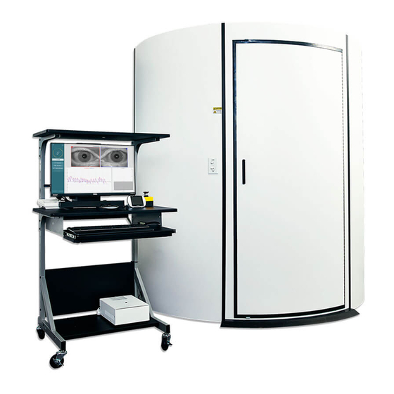
Page 38: Cart Configuration
Cart configuration If a cart is configured with the system, use the manufacturer’s assembly instructions to assemble the cart as the cart styles may vary. Example of a chair equipment cart assembled with accessories for Orion AT/C chair is shown below. -
Page 39: Connections Between Accessories
Ensure that the E-stop is disengaged by twisting it clockwise. The pictorial representation of all the configurations with Orion AT/C chair is mentioned below. Note: Use cable ties on the cables once the equipment position is determined. Use cable ties to group the motor and instrument cables to make them neat. -
Page 40: System Check On Working Condition
Once the chair stops moving, click Stop. Then click Go under Velocity Tach Calibration. The chair will spin CW. Two lines will be shown and eventually be superimposed. The calibration will stop automatically. D-0120794-C – 2019/11 Orion Rotary Chair Installation Instructions Page 35... - Page 41 Right). Click on the Center Laterally button to move the chair to center. Caution: Do not attempt to move the chair frame laterally by pushing on the chair frame or damage may occur. D-0120794-C – 2019/11 Orion Rotary Chair Installation Instructions Page 36...
-
Page 42: Laser Check
The drum should rotate first one way then the other with symmetrical sine wave. The drum will stop automatically after completing the number of cycles set in the validation parameters. D-0120794-C – 2019/11 Orion Rotary Chair Installation Instructions Page 37... - Page 43 Stop. Then click on Go button under Velocity Tach calibration. The drum will begin to rotate. Make sure the direction is CCW. Two lines will be shown and eventually be superimposed. The calibration will stop automatically. D-0120794-C – 2019/11 Orion Rotary Chair Installation Instructions Page 38...
-
Page 44: Safety Checks
VisualEyes software and clicks on Begin Testing or goes into System Default Settings Rotational Chair and selects Orion A/C. Exiting VisualEyes will turn off the Estop light after a few seconds. This ensures the Watchdog safety is working. - Page 45 Other : Date : Person : Please provide e-mail address or fax No. to whom Interacoustics may confirm reception of the returned goods: The above mentioned item is reported to be dangerous to patient or user In order to ensure instant and effective treatment of returned goods, it is important that this form is filled in and placed together with the item.
Need help?
Do you have a question about the Orion and is the answer not in the manual?
Questions and answers