Advertisement
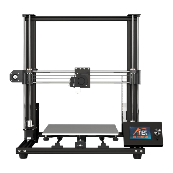
A8 Plus
3D Printer User Manual
If you have any problems with the product ,you can obtain relevant services through
the following channels :
Facebook After–sales group: www.facebook.com/groups/anet3dprintersupport
Anet official website: www.anet3d.com
After–sales service email: anet@anet3d.com
page1of36
Advertisement
Table of Contents

Related Manuals for Anet A8 Plus


Summary of Contents for Anet A8 Plus
- Page 1 A8 Plus 3D Printer User Manual If you have any problems with the product ,you can obtain relevant services through the following channels : Facebook After–sales group: www.facebook.com/groups/anet3dprintersupport Anet official website: www.anet3d.com After–sales service email: anet@anet3d.com page1of36...
-
Page 2: Table Of Contents
Catalogue Preface 1.Use Instruction……………………………………………………………………………..…4 2.Installation Instructions…………………………………………………………… …… 6 3.Spare Parts List……………………………………………………………………………..7 4. Product Parameter…………………………………………………………………………8 5. Name of Machine Parts………………………………………………………………..9 6. Machine Installation………………………………………………………………………10 7. Machine Function Introduction ……………………………………………………21 7.1 Operation Interface ……………………………………………......21 7.2 First Printing …………………………………………………………………………….25 7.3 Unload Filament …… ……………………………………………………………….…31 7.4 Change Nozzle ………………………………………………………………………... -
Page 3: Preface
Preface Dear customer : Thanks for choosing and using Anet 3D printer. For your convenience, please read the instructions carefully before using them and follow the instructions strictly. Special Version: 1. All the contents in this manual have been checked carefully. If there is any misprint or misunderstanding of them, Anet reserves the right to interpret it . -
Page 4: Use Instruction
Use Instruction In order to prevent damage to you and others in the process of using, Please be aware of the following: Do not attempt to use the machine in any way undescribed in the instructions to avoid ● accidental personal injury and property damage. Do not place this machine near inflammable and explosive materials or high heat sources. - Page 5 Children under 14 years old or people above 60 years old, please use this machine under the ● adult people to avoid personal injury. Some filaments will produce slight odor but it won't make people feel uncomfortable , so it is ● recommended that you use A8 Plus in a well-ventilated environment. page5of36...
-
Page 6: Installation Instructions
2 Installation Instructions ●Please make sure the packing is intact before receiving the goods. ●After unpacking, please check carefully whether the parts list is consistent with the physical parts. ●If you have any problems, please contact your supplier in time. ●Pictures in this manual are for your reference ,please take the object as the standard . -
Page 7: Spare Parts List
Rubber finger cot Tool bag (Hexagon wrench bag、 Mainboard kit Transparent ruler、Plier、 Screwdriver) A8 Plus electronic data Display screen TF card Display screen holder PLA filament*10m Filament holder Notes: 1. Random accessories shipped in different batches will vary slightly in color, model and brand, but will not affect your use. -
Page 8: Product Parameter
4 Product Parameter Model: A8 Plus Nozzle diameter: 0.4mm Layer precision: 0.1-0.4mm Product dimensions: 612*462*573 mm Printing speed: 40-120mm/s Product weight: 10kg XY axis position precision: 0.015mm Packing dimensions: 600*570*215mm Z axis position precision: 0.004mm Packing weight: 12.8kg Printing material: ABS, PLA, HIPS etc. -
Page 9: Name Of Machine Parts
Name of Machine Parts page9of36... -
Page 10: Machine Installation
6. Machine Installation Step 1 Name Qty. Chassis kit Vertical Frame kit M5*20 Socket hexagon screw M5*20 After assembly Before assembly Vertical frame kit Note: Chassis kit 1.The vertical frame kit is placed on the chassis kit, aligned with the hole position on the aluminum profile of the chassis, and the vertical frame and chassis are fixed with 4 M5 * 20 screws. - Page 11 Step 2 Name Qty. Step 1 Power supply kit X Limit switch KB2.3*12 Cross recessed countersunk screw KB2.3*12 After assembly Before assembly Note: 1. Install the X axis limit switch as shown above. 2. Install the power supply unit on the aluminum profile card slot. page11of36...
- Page 12 Step 3 Name Qty. Step 2 Z axis limit switch kit As shown in the picture, install the limit switch at the Z1 axis. The installation position of the Z axis limit switch is 80 mm away from the Y axis profile 80mm page12of36...
- Page 13 Step 4 Name Qty. Mainboard kit After disassembly Before disassembly Note: Split the motherboard kit, retain the 4 M3 * 6 hexagon socket screws, and then install the M4 * 8 hexagon socket screws and T nuts in the 3 holes on the mainboard.
- Page 14 Step 5 Name Qty. Step 3, Step 4 Cable bag 1.Disassemble the mainboard kit shell and fixed it into the groove. 2.Machine wiring: the wire of the extruder is wrapped with winding pipe, then it passes through the wire hole on the shell together with the left X axis limit switch wire and the X axis motor wire(as shown below picture).
- Page 15 Step 6 According to the schematic diagram of the line port and the label of the wiring, find the corresponding wiring and plug in all the wiring Wiring sheet: Name Wiring label Mainboard port Name Wiring label Mainboard port Z axis motor X-Motor X axis limit switch X axis limit switch line...
- Page 16 There is no need to separate positive and negative electrodes There is no need to separate positive and negative electrodes (+ red line , - black line ) page16of36...
- Page 17 1.Except that the electronic wire shown in step 5 passes through the jack at the upper end of the main board, the remaining electronic wires are all pulled out from the holes under the main board, and the machine is connected from below the machine to avoid affecting the operation of the machine.
- Page 18 Remove the zip ties on the black belt Name Qty. Step 7 Step 6 Display screen base Display screen kit Before assembly After assembly After the installation of the display screen is completed, place it directly on the magnet to complete the installation of the display screen kit.
- Page 19 Step 8 Name Qty. Step 7 Filament holder M4*8 Hexagon socket screw M4 T nut After assembly Before assembly The rack is installed at the position shown ( 10 cm from the front X axis ) page19of36...
- Page 20 Final schematic diagram Front Back page20of36...
-
Page 21: Machine Function Introduction
7 Machine Function Introduction 7.1 Operation Interface Actual temperature Target temperature Target temperature Actual temperature of heating bed of extruder of extruder of heating bed Knob (left and right for selection, press for confirmation) XYZ axis coordinates Speed adjustment ratio Printing time Reset button Printing... -
Page 22: First Printing
7.2 First Printing 7.2.1 Install TF Card Insert TF as shown in picture 2 TF card TF card installation position TF card installation completed 7.2.2 Machine leveling 1. Auto home operation: Adjust the spring around the heating bed to the tightest ( counterclockwise ), press the knob to enter the main menu, select“Prepare”→“Auto home”, the machine begins to move toward the position of the limit switch until it stops moving after touching the limit switch. - Page 23 2.Disable steppers operation: Press the knob to enter the main menu, select“Prepare”→“Disable steppers”. 3.Manual leveling:Move the extruder to the heating bed, and observe the distance between the extruder and the heating bed from the front of the machine. if the distance between the extruder and the four corners of the heating bed is 0.1 mm ( using a piece of A4 paper to assist leveling, A4 paper can pass through the gap and feel slight resistance ), leveling is not required.
- Page 24 Adjust the gap: Fine - tuning the " gap" to make the gap size about 0.1 mm meet the printing requirements, moving the extruder to the other three corners of the heating bed, and sequentially adjusting the spring compression of the four corners of the heating bed in one direction ( clockwise or counterclockwise ), so that an A4 paper ( about 0.1 mm ) can pass through this gap and feel a slight resistance, and there is no scratch on the platform when moving the extruder.
- Page 25 7.2.3 Load Filament 1. Perheat Machine Before loading filament, the machine needs to be preheated. The following pictures illustrates PLA filament as an example, and the operation is as follows. Operating method: Press the knob→“Prepare”→“Preheat PLA”→“Preheat PLA”, the machine starts to perheat ( the main interface shows that the machine is perheat ).
- Page 26 2. Load Filament Filament Specification: Diameter :1.75mm ;Matrial :PLA; Printing temperature :200-230℃ The method of manually loading filament is carried out according to the steps: 1. Confirm that the extruder is preheated to 200 degrees; 2. A roll of PLA filament; 3.
- Page 27 The method of automatic loading filament : 1. A roll of PLA filament; 2. Press knob ,click “Prepare”→“Change filament” ,main interface display “Heating nozzle Please wait……” ,After the nozzle temperature rises to the target temperature, the interface displays “Wait for start of the filament change”...
- Page 28 Wait for start of the filament Heating nozzle Please wait Insert filament and press Wait for filament unload change button to continue Resume print Wait for filament extrude Wait for filament load Extrude more Note: The automatic feeding function is carried out according to the procedure of feeding after discharging. When the first printing has not yet started to install filament, please wait for the“Insert filament and press button to continue”interface to appear before inserting filament into the extruder for automatic feeding.
- Page 29 2. In the process of printing, if you want to pause printing, press the knob to enter the main menu, press " Prepare" → " Pause print" to pause printing, and press " Resume print" to resume printing. 3. If you want to stop printing during printing, press the knob to enter the main menu, press " Prepare" →...
- Page 30 4 Remove Model After the model printing is finished, the model is shoved down against the glass surface with a shovel. page30of36...
-
Page 31: Unload Filament
Unload Filament Withdrawal of filament shall be described in terms of manual and automatic methods Pull out filament vertically Method of manually unload filament ( taking PLA as an example ) 1. Preheat the printer to 200 degrees; 2. After reaching 200 degrees, push down the filament to a section of filament, then pull up the filament at a constant speed, press the extrusion head port with the thumb, pull the base with the index finger, and take out the filament at the same time;... -
Page 32: Change Nozzle
Filament Replacement Precautions: 1. When the printing of a roll of filament is nearing the end, in order to avoid the problem of secondary material change caused by too deep a supply of filament, remember not to let the machine feed all the materials into the feed opening and replace the new filament in time. - Page 33 Change Nozzle Change nozzle as shown below: M6 Nut Wind mouth M3*4 Black jackscrew Picture 15 Changing nozzle is according to the following steps ( the nozzle in a cooling state ): 1. Disassemble the two M3 * 4 jackscrew on the extruder and take out the heating tube; 2.
-
Page 34: Faq
8. FAQ Failure Situation Failure Cause Solution The gear is loose or the Tighten the jackscrewon the gearwheel or Printing model misalignment belt is loose tighten the belt Check whether the thermistor next to the heating block slides out of the air, the Nozzle drawing when printing High temperature or slicing extrusion head temperature is set too... -
Page 35: Machine Maintenance
9. Machine Maintenance The 3D printer can run continuously for tens of hours or more. Some parts that work for a long time, especially some parts that move continuously need to be maintained. Here are some instructions on how to maintain the machine. - Page 36 forward and reverse directions by hand. If the distance before and after the extrusion mechanism moves is not equal, it is too loose. You can also press the middle of the belt by hand. If the radian of lightly pressing the belt is large, it means the belt is too loose. 4.
Need help?
Do you have a question about the A8 Plus and is the answer not in the manual?
Questions and answers