Table of Contents
Advertisement
Advertisement
Table of Contents

Related Manuals for Anet A8 PLUS


Summary of Contents for Anet A8 PLUS
- Page 1 User Manual If you have any problems with the product, you can obtain the relevant services through the following channels : Facebook after - sales group: www.facebook.com/groups/anet3dprintersupport Anet official website: www.anet3d.com After – sales service email: anet@anet3d.com...
-
Page 2: Table Of Contents
CONTENTS Preface 1. Use Instruction 2. Installation Instruction 3. Spare Parts List 4. Parameter 5. Name of Parts 6. Installation 7. Machine Function Introduction 7.1 Operation Interface 7.2 First Printing 7.2.2 Machine leveling 7.2.3 Load Filament 7.2.4 Remove Model 7.2.5 Unload Filament... -
Page 3: Preface
Special Version: 1. All the contents in this manual have been checked carefully. If there is any misprint or misunderstanding of them, Anet reserves the right to interpret it. 2. This user manual is for reference only and does not constitute any form of commitment. -
Page 4: Use Instruction
Use Instruction In order to prevent damage to you and others in the process of using, Please be aware of the following: Please do not attempt to use the machine in any way undescribed in the instructions to avoid accidental personal injury and property ●... -
Page 5: Installation Instruction
●Please make sure the packing is intact before receiving the goods. ●After unpacking, please check carefully whether the parts list is consistent with the physical parts. ●If you have any problems, please contact your supplier or Anet in time. 3 Spare Parts List... - Page 6 A8 Plus Parts List 1 Picture Name Qty. Picture Name Qty. X axis aluminum Power supply kit profile 472mm Y axis aluminum Mainboard kit profile 422mm Z axis aluminum Extruder kit(Black) profile 500mm Environmentally friendly rubber X axis guiding rod...
- Page 7 Picture Name Qty. Picture Name Guiding rod shaft Limit switch sleeve Leading rod fixed Z axis limit switch holder block 5015 air blower bag Limit switch line Wind mouth GT2 belt bag 2m Fan bag Z1 axis motor fixed plate Z2 axis motor fixed plate Spare parts Z axis guiding rod fixed plate...
- Page 8 A8 Plus Parts List 3 Picture Name Qty. Picture Name Qty. Tool bag Filament holder kit 2 PLA filament*10m Protective tube bag(10A/15A) FPC grey ribbon line Screw bag 2 bag 1000mm (M3*20/M3*25 、 M5*20/M5*30) Red and black belt Screw bag 3...
- Page 9 Heating bed 300*300*3mm A8 Plus electronic data Tempered glass (TF card, reader) Display screen Filament holder kit 1...
-
Page 10: Parameter
4 Product Parameter Model:A8 PLUS Nozzle diameter: 0.4mm Layer precision:0.1-0.4mm Product dimension:612*462*573mm Printing speed: 40-120mm/s Product weight: 10±0.1kg XY axis position precision:0.015mm Packing dimension:580*375*175mm Z axis position precision:0.004mm Packing weight: 12.1±0.1kg Printing material: PLA, ABS, HIPS etc. Build volume:300*300*350mm Filament tendentiousness:PLA LCD:12864 LCD... -
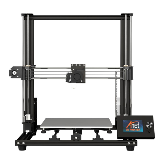
Page 11: Name Of Parts
5. Name of Parts... - Page 12 Step 1 Name Qty. X axis aluminum profile 472mm Y axis aluminum profile 422mm End cap M5*20 Environmentally friendly rubber pillar washer M5*20 socket hexagon screw The Y axis is separated from the hole position, the front section is long, and the rear section is short. Before assembly After assembly Short...
- Page 13 Step 2 Name Qty. Y axis guiding rod 442mm Linear bearing kit Leading rod fixed block Leading rod –limit switch mounting block with pulley Limit switch without pulley Self-tapping screw KB2.3*12 Before assembly After assembly...
- Page 14 Step 3 M4*14 Name Qty. M4*14 T – nut Before assembly After assembly End cap Attention: The size of the double arrow in the drawing is 132 mm ( the distance from the center of the leading rod fixed block to the edge of the profile ), which is controlled during assembly.
- Page 15 Step 4 Name Qty. Y axis motor fixed plate Y axis motor kit socket hexagon screw M3*6 socket hexagon screw M4*8 M4 T – nut M4 Note: 1. Please fix it in the center of rear X axis aluminum Note: Fix the Y axis motor fixed plate to the Y axis motor profile M3*6 screw...
- Page 16 Step 5 Name Qty. Y axis belt bearing fixed kit M4*8 Socket hexagon screw T-nut M4 1.ease fix it in the center of front X axis aluminum profile. 2.M4 * 8 screws pass through the , screw on the T - nut Y axis motor fixed plate ( entering 2 - 3 thread teeth ), put it into the X - axis profile slot, tighten the screw ( the nut will rotate 90 degrees during this process ), and corner bracket...
- Page 17 Step 6 Name Qty. Hotbed support Hotbed shelf M4*8 Socket hexagon screw Cylindrical head screw M4*14 Black Fix M4*14 screw in the left hole Before assembly After assembly...
- Page 18 Step 7 Name Qty. Belt Belting After assembly Before assembly Note: The belt is cut to a proper length and fixed on the two M4 * 14 crews in step 6, Please tighten the belt and press it to see if it is loose.
- Page 19 Name Qty. M4*25 Step 8 Spring Plastic hand screw Heating bed300*300*3mm M4*25 Toughened glass Clips Before assembly After assembly M4*25 Heating bed Spring Hotbed support Plastic hand screw Attention: Fix the hot bed on the h in sequence as shown in the picture. eating bed support...
- Page 20 Step 9 Name Qty. Right Z axis screw rod nut support X axis motor kit Limit switch with pulley Socket hexagon cylindrical head screw M3*20 Cross recessed countersunk screw KB2.3*12 Before assembly After assembly The motor connection port is facing down, as shown in the figure...
- Page 21 Step 10 Name Qty. Linear bearing 496mm X axis guiding rod Right Z axis screw rod nut support Before assembly After assembly Attention: Please install in the direction shown in the picture.
- Page 22 Step 11 Name Qty. Extruder kit After disassembly Before disassembly M3*6 Loosen the nut and exit the extruder L-shaped black aluminum Extruder 1. Loosen the nut and separate the extruder from the L-shaped black aluminum . 2..Remove the 2 M3*6 screw and use them later.
- Page 23 Step 12 Name Qty. L-shaped aluminum holder Socket hexagon screw M4*6 Before assembly After assembly Fix the L-shaped aluminum holder in the linear bearing...
- Page 24 Step 13 Name Qty. Extruder Before assembly After assembly Put the extruder into the L-shaped aluminum holder and tighten the nut...
- Page 25 Name Qty. Step 14 Fan fixed plate Air blower Wind mouth M3*15 Socket hexagon screw M3*15 Ø3 Gasket Socket hexagon screw M3*6 Socket hexagon screw M3*18 After assembly Before assembly M3*15+ φ3 M3*6 M3*18 Fix the fan fixed plate in the L-shaped aluminum holder with 2 M3*6 screw...
- Page 26 Step 15 Name Qty. Belt Belt adjusting fixing block Belt adjusting sliding block M3*25 Socket hexagon screw M3 nut M3*10 Countersunk screw After assembly Before assembly Gear Flanged Bearing M3 nut M3*25 Connect the gear and flanged bearing with a belt ,and sleeve the belt adjusting fixing block and sliding block, after fixing ,press The fixing block is fixed with M3*10 countersunk...
- Page 27 Step 16 Name Qty. Z1 axis motor fixed plate Z2 axis motor fixed plate Z axis motor kit M3*6 Socket hexagon flat round head screw M3*6 Socket hexagon flat round head screw M4*8 M4 T-nut Before assembly After assembly Please install as shown in the figure, pay attention to the direction relationship between the circular hole and the motor.
- Page 28 Step 17 Name Qty. Z axis aluminum profile 500mm Before assembly After assembly The T-nut is inside the profile clamping groove Z1 in the left ,Z2 in the right.
- Page 29 Step 18 Name Qty. 486mm Z axis guiding rod 486mm 462mm Z axis screw rod 462mm Lock the self-contained top tightening screw Before assembly After assembly 462mm*2 486mm*2 Note: Rotate the screw rod clockwise down to the bottom, and then lock the self-contained top tightening screw...
-
Page 30: Guiding Rod Shaft Sleeve 2
Step 19 Name Qty. Guiding rod shaft sleeve M3*4 Black jackscrew M3*4 Z axis guiding rod fixed plate M5*30 Socket hexagon cylindrical head M3*4 screw End cap X axis aluminum profile 472mm After assembly Before assembly Z axis M5*30 Guidi guiding ng rod shaft... -
Page 31: Corner Bracket 2
Step 20 Name Qty. M4*8 socket hexagon screw M4 T-nut M5*20 Socket hexagon cylindrical head screw After assembly Before assembly Vertical Frame Corner bracket installation: Make the screws through the corner bracket, screw on the T - nut ( 2 - 3 thread tooth ), put it into the profile slot ( inside ), tighten the screws with a wrench, and the T - nut will rotate 90 degrees and the corner bracket will be fixed. -
Page 32: Installation
Step 21 Name Qty. Power supply kit Remove the M3 * 6 socket hexagon screw Mainboard kit for fixing the power supply, split the power supply and power supply fixing frame, and retain the 3 inner hexangular set screws. Before assembly After assembly The circle is an enlarged view ( side ) of the T - nut... - Page 33 Step 22 Name Qty. Power outlet Red and black with U-shaped line (Double head) The circle is an M3*6 M4*6 socket hexagon screw enlarged view T-nut M4 ( side ) of the T - M3*6 socket hexagon screw nut installation Before assembly After assembly 1 2 3 4 5 6 7 8 9...
-
Page 34: Limit Switch
Name Qty. KM2*10 M4*8 cross recessed countersunk screw T-nut M4 Limit switch (without pulley)/Limit switch support A8 plus motor line bag Heating tube6*20mm( with line 1.5m) Hotbed line FPC grey ribbon line bag Limit switch Z1 axis M4*6 Z2 axis... -
Page 35: Limit Switch Line
Step 24 Name Qty. Motor line bag The cable with the word "-A" is connected to one end of the FPC grey ribbon line bag Limit switch line bag mainboard. Pass all other wires through the holes Please pass the lines(with -A word) of extruder, X under the mainboard (The cable with the axis limit switch and X axis motor through the word "-A"... - Page 36 Step 25 According to the schematic diagram of the line port and the label of the wiring, find the corresponding wiring and plug in all the wiring, the cable with the word "-A" is connected to one end of the mainboard. Wiring sheet:...
-
Page 37: Power Line,
2. When all wiring is plugged in, please remove the zip ties on the black belt, plug in the power line, turn on the machine for trial operation(please refer 7.2 First Printing ), and then install the mainboard shell after everything is normal. Heating bed TF card port There is no need to separate... -
Page 38: M4*8
Step 26 Name Qty. Display screen base Display screen T-nut M4 M4*6 Magnet After assembly Before assembly M4*6 magnet Display bas Note: 1. The LCD / J3 wiring of the display screen corresponds to the socket screen printing ( LCD / J3 ) on the control panel. Please do not connect the wrong wiring. - Page 39 Step 27 Name Qty. Filament holder M4*8 T-nut Before assembly After assembly...
- Page 40 Step 28 Final Schematic diagram Back Front...
-
Page 41: Machine Function Introduction
7 Machine Function Introduction 7.1 Operation Interface Target temperature Actual temperature of heating bed Actual temperature Target temperature of extruder of extruder of heating bed Rotary button (left and right for selection, press for confirmation) XYZ axis coordinates Speed adjustment ratio Printing time Status bar Printing... -
Page 42: First Printing
7.2 First Printing 7.2.1 Install TF Card Insert TF as shown in picture 2 TF card installation completed TF card 7.2.2 Machine leveling 1. Auto home operation: Adjust the spring around the heating bed to the tightest ( counterclockwise ), press the rotary button to enter the main menu, select“Prepare”→“Auto home”, the machine begins to move toward the position of the limit switch until it stops moving after touching the limit switch. - Page 43 nozzle and the four corners of the heating bed is greater than or less than 0.1mm, adjust according to step 4. The distance between the nozzle and heating bed 4. Adjust the distance: Fine - tuning the "distance" to make its size about 0.1mm meet the printing requirement. Move the nozzle to the other three corners of the heating bed, and sequentially adjusting the spring compression of the four corners of the heating bed in one direction (clockwise or counterclockwise), so that an A4 paper (about 0.1mm) can pass through this distance and feel a slight resistance, and there is no scratch on the platform when moving the extruder.
-
Page 44: Load Filament
7.2.3 Load Filament 1. Perheat Machine Before loading filament, the machine needs to be preheated. The following pictures illustrates PLA filament as an example, and the operation is as follows. Operating method: Press the knob→“Prepare”→“Preheat PLA”→“Preheat PLA”, the machine starts to perheat ( the main interface shows that the machine is perheat ). - Page 45 2 Load Filament Load filament automatically: 1. A roll of PLA filament: Filament specifications: Diameter :1.75mm; Material: PLA ;Printing temperature: 200-230℃; 2.Please press rotary button → “Prepare” → “Change filament” , the main interface will display “Heating nozzle Please wait……” ,the interface will display “Wait for start of the filament change”...
- Page 46 Wait for start of the filament change Wait for filament unload Insert filament and press button to continue… Heating nozzle Please wait… Wait for filament load Resume print Wait for filament extrude Extrude more...
- Page 47 3 Printing 1. After leveling is completed and the filament is installed successfully, press the rotary button to enter the main menu, press " Print from SD" → " Main" and select the file under " Main" to start first printing. 2.
-
Page 48: Remove Model
7.2.4 Remove Model Please remove the model by hand after printing . 7.2.5 Unload Filament Automatic unload filament (taking PLA as an example) Please press rotary button → “Prepare” → “Change filament” , the main interface will display “Heating nozzle Please wait……” ,wait for 1-2 mins ,the interface will display“Wait for start of the filament change”after the nozzle temperature rises to the target temperature →“Wait for filament unload ”...
Need help?
Do you have a question about the A8 PLUS and is the answer not in the manual?
Questions and answers