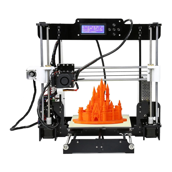
Anet A8 Installation Manual
Hide thumbs
Also See for A8:
- Quick user manual (48 pages) ,
- Installation manual (38 pages) ,
- Instructions manual (19 pages)
Advertisement
Quick Links
Advertisement

Summary of Contents for Anet A8
- Page 1 A8 3D Printer Installation Guide...
- Page 2 A8 Assembly Instructions Attention: 1. Please make sure the package not broken when you receive 2. Please check the printer parts according to the packing list. 3. Please contract your supplier if any questions. the installation of graphics and text for the model 4....
- Page 3 A8 assembly parts list 1...
- Page 4 A8 assembly parts list 2...
- Page 5 该文档是极速PDF编辑器生成, A8 assembly parts list 如果想去掉该提示,请访问并下载: http://www.jisupdfeditor.com/...
- Page 6 A8 assembly parts list 4...
- Page 7 该文档是极速PDF编辑器生成, 如果想去掉该提示,请访问并下载: http://www.jisupdfeditor.com/ A8 assembly parts list 5...
- Page 8 该文档是极速PDF编辑器生成, 如果想去掉该提示,请访问并下载: http://www.jisupdfeditor.com/ A8 assembly parts list 6 Pleasecheckprinterpartsquantitywhenyoureceiveit.
- Page 9 Name of each printer part...
-
Page 10: Assembly Step
Assembly Step 1 Please be aware the screw holes is in red circles Step1... - Page 11 Assembly Step 2 Pleasebeawarethescrew holes is in black circles Step 2...
- Page 12 Assembly Step 3 Y axis motor and wire 400mm Motor fixing plate Y axis position switch 700mm Step Rear fixing plate...
- Page 13 Assembly Step 4 Step 2 Step 3...
- Page 14 Assembly Step 5...
- Page 15 Assembly Step 6 Threaded rod 400mm...
- Page 16 Assembly Step 7 Y Guide rod 380mm...
- Page 17 Assembly Step 8 Attention : Leave vacancy between belt fixation clamp and hot bed fixedplateforbelt positioning.
- Page 18 该文档是极速PDF编辑器生成, Assembly Step 9 如果想去掉该提示,请访问并下载: http://www.jisupdfeditor.com/ Before Assembly After Assembly Attention:Please diagonallytighten thescrews when allareinthereplace...
- Page 19 Assembly Step 10 Attention:Beltisfor X&Y axistransmitting.Cutthe length you needto eachtransmissionshaft.Thebeltis1.5m intotaland10-20 cm left after installation.
- Page 20 Assembly Step 11 wing nuts will keep the height of hot bed level as well as firming the hotbed. Attention:Hot bed screws should be in the bottom, and...
- Page 21 该文档是极速PDF编辑器生成, Assembly Step 12 如果想去掉该提示,请访问并下 Attention: This hole is for Z axis guide rod p 载: p:// u pd o r.c...
- Page 22 该文档是极速PDF编辑器生成, 如果想去掉该提示,请访问并下载: http://www.jisupdfeditor.com/...
- Page 23 Assembly Step 14...
- Page 24 Assembly Step 15 Attention: loose the jackscrew of elastic coupling to place T lead screw tothe bottom, then tighten T lead screw 345mm...
- Page 25 Attention: Please keep A&B at the same level during 该文档是极速PDF编辑器生 成, Assembly Step 如果想去掉该提示,请访问并下载: http://www.jisupdfeditor.co X rods installation. Knock the guide rods with a hammer slightly if it’s hard toplace. X axis Guide rod 436mm After installation tighten the top wire at the back...
- Page 26 Assembly Step 17 After disassembly Beforedisassembly After disassembly Loose M4*6 screws first, thenseparate extruder from L black aluminum parts, rememberto...
- Page 27 Assembly Step 18 Replace M3*20 screws with M3*45 screws M3*45 screwholes...
- Page 28 该文档是极速PDF编辑器生成, 该文档是极速PDF编辑器生成, 如果想去掉该提示,请访问并下载: Assembly Step 如果想去掉该提示,请访问并下载: http://www.jisupdfeditor.com/ http://www.jisupdfeditor.com/...
- Page 29 该文档是极速PDF编辑器生成, Assembly Step 20 如果想去掉该提示,请访问并下载: http://www.jisupdfeditor.com/ Attention: Install M4*6 screw. Tighten M6 Screw on the throat with spanner till extruder is not loose.
- Page 30 Assembly Step...
- Page 31 Assembly Step 22 M3*20...
- Page 32 AssemblyStep 23 Attention: Belt is for X,Yaxis transmitting . The length of belt is 1.5m in total. Normally there’ll be 10-20cm left after installation.
- Page 33 Assembly Step 24 M3 Nut...
- Page 34 Assembly Step...
- Page 35 Assembly Step AttentionThisisthewiringdiagramofpowersupply. 1,2,3seperatelyrepresent theline of fire (brown),Zero line (blue), ground wire (yellow). 4,5, 6 represent negative pole (black) (-);7,8,9represent thepositivepole(red) (+).Toavoiddanger,please assure the installation is correct .
- Page 36 该文档是极速PDF编辑器生成, 如果想去掉该提示,请访问并下载: Assembly Step http://www.jisupdfeditor.com Redcirclesstandfor thepower screw holes PowerSupply...
- Page 37 Assembly Step 28 Mainboard...
- Page 38 Assembly Step 29 Attention: Please use the corresponding wire , especially motor wire & limited switch wire.
- Page 39 Assembly Step 30 Attention: Please connect the electronics wire to each components correspondingly.
- Page 40 该文档是极速PDF编辑器生成, 如果想去掉该提示,请访问并下载: http://www.jisupdfeditor.com/...
- Page 41 Assembly Step 32 Installation Picture 1...
- Page 42 Assembly Step 32 Installation Picture 2...
- Page 43 Assembly Step 32 Installation Picture 3...
-
Page 44: Installation Complete
Installation Complete • Congratulations!Youhavejustmadeyourselfa3D printer ! • Please contact your 3D printer supplier if any puzzles during using process. • Thank you for choosing our products, we will alwaysprovide you more services.


Need help?
Do you have a question about the A8 and is the answer not in the manual?
Questions and answers