Advertisement
Table of Contents
- 1 Table of Contents
- 2 Preface
- 3 Use Instruction
- 4 Installation Instruction
- 5 Spare Parts List
- 6 Parameter
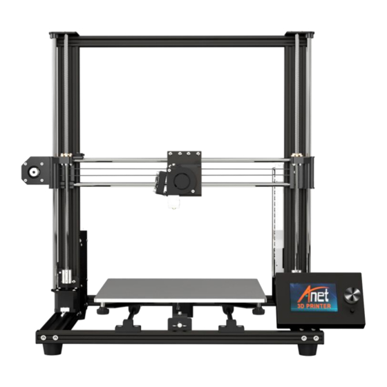
- 7 Name of Parts
- 8 Machine Function Introduction
- 9 Operation Interface
- 10 First Printing
- 11 Machine Leveling
- 12 Load Filament
- 13 Remove Model
- 14 Unload Filament
- Download this manual
See also:
User Manual
Advertisement
Table of Contents

Subscribe to Our Youtube Channel
Related Manuals for Anet A8 Plus


Summary of Contents for Anet A8 Plus
- Page 1 User Manual If you have any problems with the product, you can obtain relevant services through the following channels: Facebook after - sales group: www.facebook.com/groups/anet3dprintersupport Anet official website: www.anet3d.com After – sales service email: anet@anet3d.com page1of30...
-
Page 2: Table Of Contents
CONTENTS Preface 1. Use Instruction……………………………………………………………………………..…4 2. Installation Instruction…………………………………………………………… …… 6 3. Spare Parts List……………………………………………………………………………..7 4. Parameter…………………………………………………………………………8 5. Name of Parts………………………………………………………………..9 6. Installation………………………………………………………………………10 7. Machine Function Introduction ……………………………………………………21 7.1 Operation Interface ……………………………………………......21 7.2 First Printing …………………………………………………………………………….25 7.3Machine leveling 7.4 Load Filament …… ……………………………………………………………….…31 7.5 Remove Model ………………………………………………………………………... -
Page 3: Preface
Preface Dear customer: Thanks for choosing and using Anet 3D printer. For your convenience, please read the instructions carefully before using them and follow the instructions strictly. Special Version: 1. All the contents in this manual have been checked carefully. If there is any misprint or misunderstanding of them, Anet reserves the right to interpret it. -
Page 4: Use Instruction
Use Instruction In order to prevent damage to you and others in the process of using, Please be aware of the following: Please do not attempt to use the machine in any way undescribed in the instructions to avoid ● accidental personal injury and property damage. - Page 5 Some filaments will produce slight odor but it won't make people feel uncomfortable , so it is ● recommended that you use A8 Plus in a well-ventilated environment. ● Self-disassembly or modification may cause damage or abnormal performance, and your machine will no longer enjoy warranty service.
-
Page 6: Installation Instruction
●After unpacking, please check carefully whether the parts list is consistent with the physical parts. ●If you have any problems, please contact your supplier or Anet in time. ●Pictures in this manual are for your reference ,please take the object as the standard. -
Page 7: Spare Parts List
(Gift) Tool bag (Hexagon wrench bag, Display screen transparent ruler, plier, (Gift) screwdriver) A8 Plus electronic data Display screen holder (TF card, reader) (Gift) Filament holder kit 1 PLA filament*10m (Gift) Attention: The gifts in the parts list and toughened glass do not enjoy the warranty policy. -
Page 8: Parameter
4 Parameter Model: A8 Plus Nozzle diameter: 0.4mm Layer precision: 0.1-0.4mm Product dimensions: 612*462*573 mm Printing speed: 40-120mm/s Product weight: 10kg XY axis position precision: 0.015mm Packing dimensions: 600*570*215mm Z axis position precision: 0.004mm Packing weight: 12.8kg Printing material: ABS, PLA, HIPS etc. - Page 9 page9of30...
- Page 10 6. Machine Installation Step 1 Name Qty. Chassis kit Vertical frame kit M5*20 Socket hexagon screw M5*20 After assembly Before assembly Vertical frame kit Attention: Chassis kit 1.The vertical frame kit is placed on the chassis kit, aligned with the hole position on the aluminum profile of the chassis, and the vertical frame and chassis are fixed with 4 M5 * 20 screws.
- Page 11 Step 2 Name Qty. Power supply kit X Limit switch KB2.3*12 Cross recessed countersunk screw KB2.3*12 After assembly Before assembly Attention: 1. Install the X axis limit switch as shown above. 2. Install the power supply kit on the aluminum profile card slot. page11of30...
- Page 12 Step 3 Name Qty. Z axis limit switch kit As shown in the picture, install the limit switch at the Z1 axis. The installation position of the Z axis limit switch is 80mm away from the Y axis profile 80mm page12of30...
- Page 13 Step 4 Name Qty. Mainboard kit After disassembly Before disassembly Attention: Split the mainboard kit, retain the 4 M3 * 6 hexagon socket screws. page13of30...
- Page 14 Step 5 Name Qty. Line bag 1. Disassemble the mainboard kit shell and fixed it into the groove. 2. Machine wiring: the wire of the extruder is wrapped with winding pipe, then it passes through the wire hole on the shell together with the left X axis limit switch wire and the X axis motor wire(as shown below picture).
- Page 15 Step 6 According to the schematic diagram of the line port and the label of the wiring, find the corresponding wiring and plug in all the wiring, the cable with the word "-A" is connected to one end of the mainboard. Wiring sheet:...
- Page 16 Schematic diagram of line port installation There is no need to separate positive and negative electrodes There is no need to separate positive and negative electrodes (+ red line , - black line ) Heating bed thermistor page16of30...
- Page 17 1. Except that the electronic wire shown in step 6 passes through the jack at the upper end of the mainboard, the remaining electronic wires are all pulled out from the holes under the mainboard, and the machine is connected from below the machine to avoid affecting the operation of the machine. 2.
- Page 18 Step 7 Name Qty. Display screen base Display screen kit Before assembly After assembly After the installation of the display screen is completed, place it directly on the magnet to complete the installation of the display screen kit. page18of30...
- Page 19 Step 8 Name Qty. Filament holder M4*8 Hexagon socket screw M4 T nut Before assembly After assembly page19of30...
- Page 20 Step 9 Schematic diagram of product installation completion: Front Back page20of30...
-
Page 21: Machine Function Introduction
7 Machine Function Introduction 7.1 Operation Interface Target temperature Actual temperature Target temperature Actual temperature of heating bed of extruder of extruder of heating bed Rotary button (left and right for selection, press for confirmation) XYZ axis coordinates Speed adjustment ratio Printing time Reset button Printing... -
Page 22: First Printing
7.2 First Printing 7.2.1 Install TF Card Insert TF as shown in picture 2 TF card TF card installation completed 7.2.2 Machine leveling 1. Auto home operation: Adjust the spring around the heating bed to the tightest ( counterclockwise ), press the rotary button to enter the main menu, select“Prepare”→“Auto home”, the machine begins to move toward the position of the limit switch until it stops moving after touching the limit switch. - Page 23 2.Disable steppers operation: Press the rotary button to enter the main menu, select“Prepare”→“Disable steppers”. 3.Manual leveling:Move the nozzle to the heating bed, and observe the distance between the nozzle and the heating bed from the front of the machine. If the distance between the nozzle and the four corners of the heating bed is 0.1mm (the thickness of a piece of A4 paper, A4 paper can pass through the gap and feel slight resistance), leveling is not required.
- Page 24 4. Adjust the distance: Fine - tuning the "distance" to make its size about 0.1mm meet the printing requirement. Move the nozzle to the other three corners of the heating bed, and sequentially adjusting the spring compression of the four corners of the heating bed in one direction (clockwise or counterclockwise), so that an A4 paper (about 0.1mm) can pass through this distance and feel a slight resistance, and there is no scratch on the platform when moving the extruder.
-
Page 25: Load Filament
7.2.3 Load Filament 1. Perheat Machine Before loading filament, the machine needs to be preheated. The following pictures illustrates PLA filament as an example, and the operation is as follows. Operating method: Press the knob→“Prepare”→“Preheat PLA”→“Preheat PLA”, the machine starts to perheat ( the main interface shows that the machine is perheat ). - Page 26 2. Load Filament Load filament automatically: 1. A roll of PLA filament: Filament specifications: Diameter :1.75mm; Material: PLA ;Printing temperature: 200-230℃; 2.Please press rotary button →“Prepare”→“Change filament”, the main interface will display “Heating nozzle Please wait……”,the interface will display “Wait for start of the filament change” after the nozzle temperature rises to the target temperature →“Wait for filament unload ”...
- Page 27 Wait for filament unload Wait for start of the filament change Insert filament and press button to continue… Heating nozzle Please wait… Wait for filament load Wait for filament extrude Resume print Extrude more page27of30...
- Page 28 3 Printing 1. After leveling is completed and the filament is installed successfully, press the rotary button to enter the main menu, press " Print from SD" → " Main" and select the file under " Main" to start first printing.
-
Page 29: Remove Model
4 Remove Model After the model printing is finished, the model is shoved down against the glass surface with a shovel. page29of30... -
Page 30: Unload Filament
Unload Filament Automatic unload filament (taking PLA as an example) Please press rotary button →“Prepare”→“Change filament”, the main interface will display “Heating nozzle Please wait……”,wait for 1-2 mins ,the interface will display“Wait for start of the filament change”after the nozzle temperature rises to the target temperature →“Wait for filament unload ” ,the machine automatically unload filament ,then pulls out the filament in the vertical direction and unload the filament.
Need help?
Do you have a question about the A8 Plus and is the answer not in the manual?
Questions and answers